
Study on Excavation Response of Deep Foundation Pit Supported by SMW Piles Combined with Internal Support in Soft Soil Area

Abstract
:1. Introduction
2. Project Overview
2.1. Site Overview
2.2. Hydrogeological Conditions
3. Support Structure Scheme and Construction Conditions
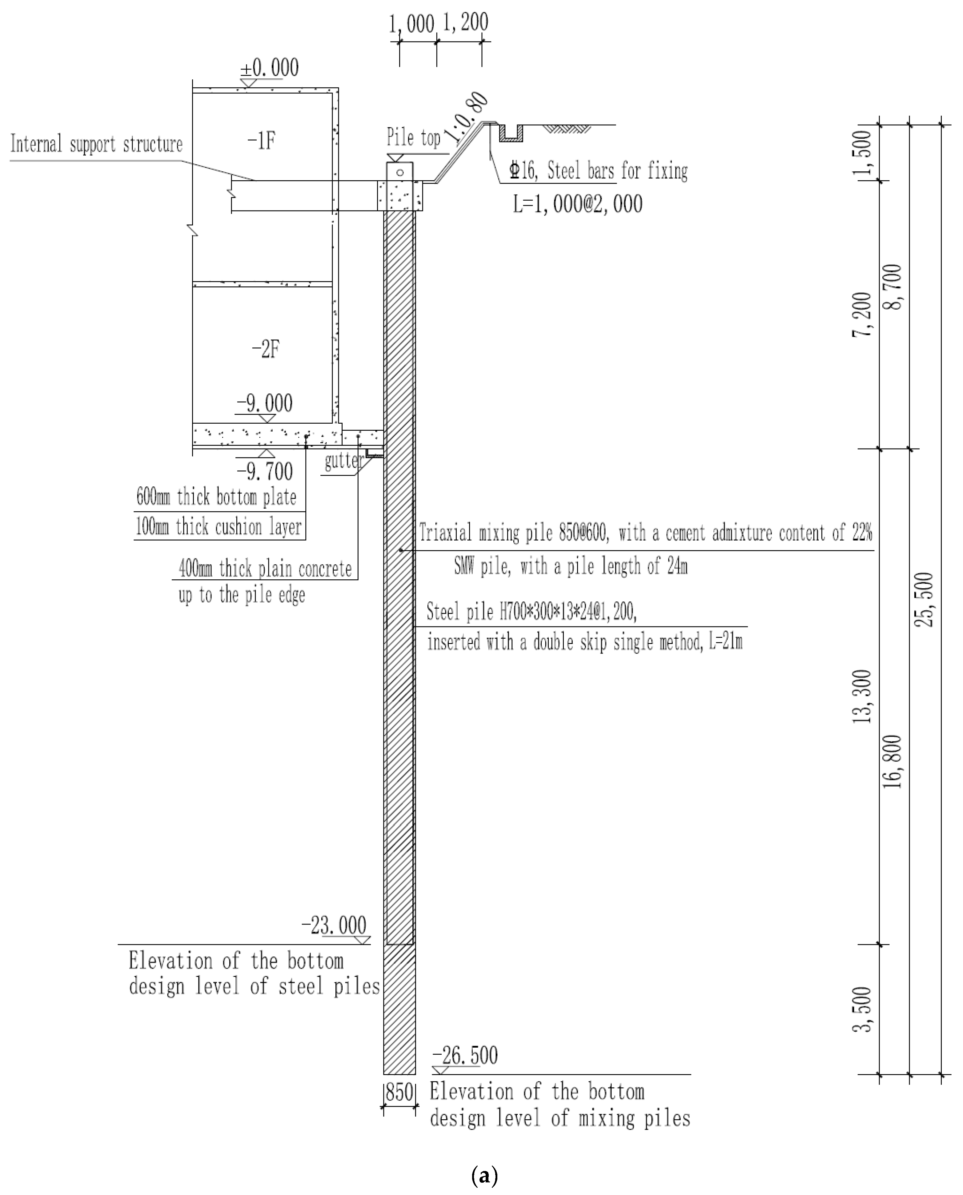
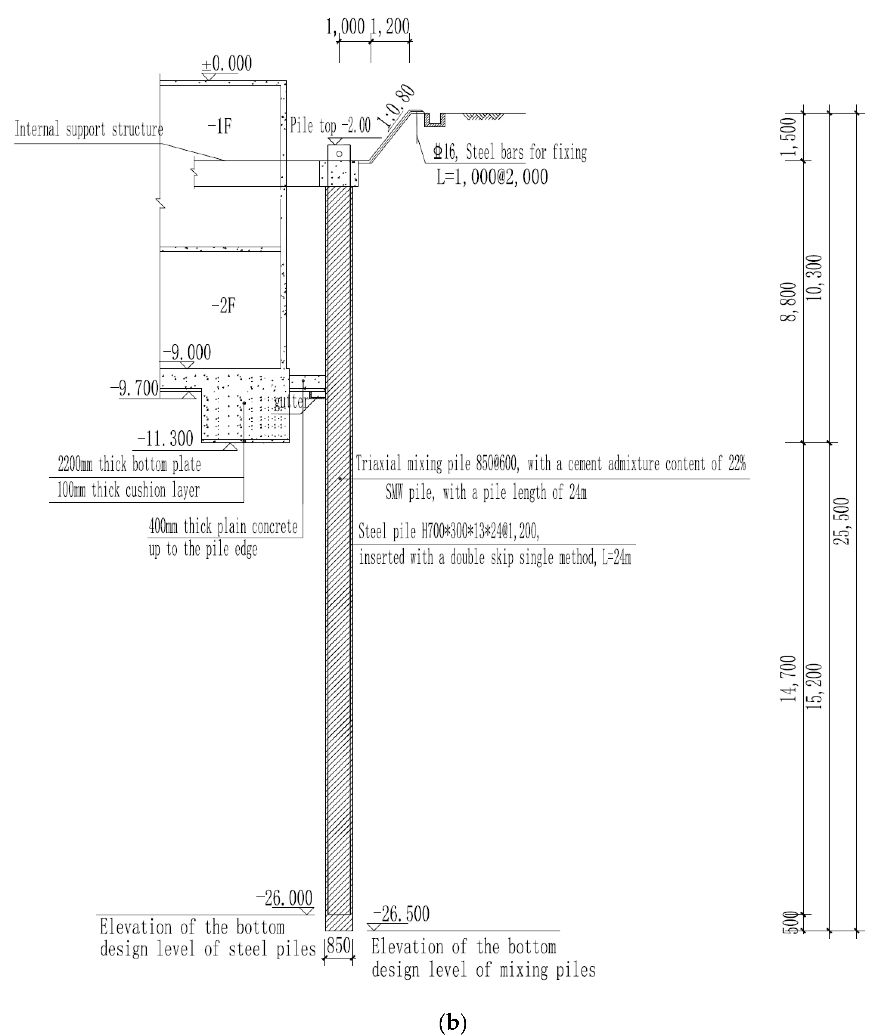
3.1. Support Structure Form
3.2. SMW
3.3. Reinforced-Concrete Inner Support
4. Excavation Monitoring and Data Analysis
4.1. Monitoring Scheme and Layout of Monitoring Points
4.2. Data Analysis
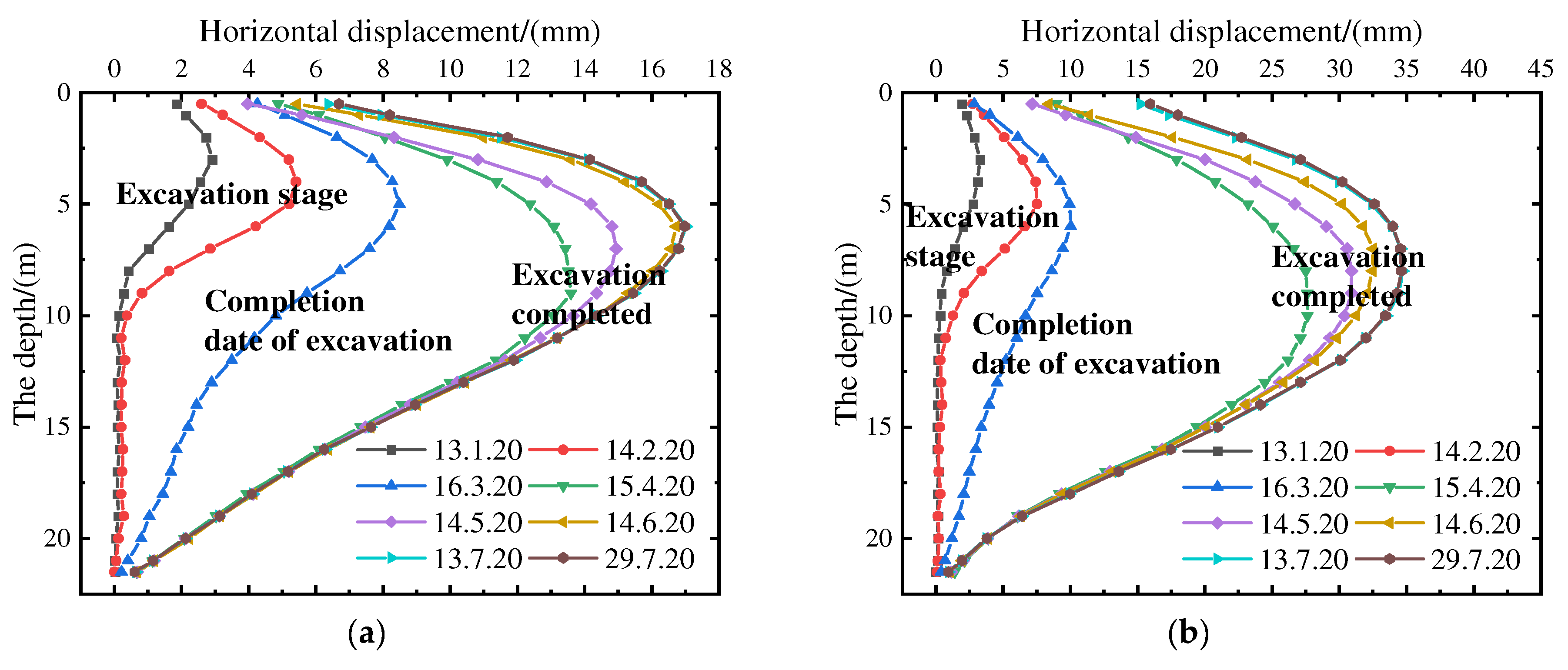
- (1)
- Deep Horizontal Displacement
- (2)
- Analysis of pile top horizontal displacement and settlement
- (3)
- Settlement Analysis of Adjacent Buildings
- (4)
- Settlement Analysis of Columns
- (5)
- Analysis of Displacement Monitoring for Surrounding Roads and Underground Pipelines
- (6)
- Analysis of Underground Water Level Monitoring
- (7)
- Stress analysis of inner support structure
- (8)
- Summary of data
5. Conclusions
- (1)
- The deformation of the combined circular internal bracing and SMW support structure in excavation projects exhibits distinct spatial distribution characteristics. Generally, the deformation lessens as the distance from the excavation corner increases, while the middle sections of the excavation walls experience more significant deformations. The excavation can also increase the deformation of the support structure. Therefore, in practical engineering, it is advisable to enhance the monitoring points or monitoring frequency in the middle section of the excavation walls and near existing structures near the top of the excavation to ensure the safety of the excavation.
- (2)
- During the construction phase, the deformations of the internal support combined with the SMW support structure exhibit a significant time effect, meaning that the deformation characteristics of the support structure vary at different excavation stages. Typically, during the initial excavation and construction phases of the internal support structure, the deformation growth rate of the support structure is relatively low. During the excavation construction phase, as the foundation pit’s excavation depth increases, the support structure’s deformation growth rate significantly increases. However, during the construction of the foundation base and backfilling of the excavation pit, the deformation growth rate of the support structure decreases significantly. Therefore, to ensure the safety of excavation construction, it is essential to closely monitor the deformation of the internal support system composed of SMW piles, particularly during the excavation phase. This will help prevent sudden excessive deformations of the support structure.
- (3)
- The deformations of the surrounding structures also demonstrate a notable ‘time effect’. Based on the analysis of monitoring data from the surrounding structures, it is evident that the settlements of adjacent buildings and the deformations of surrounding roads and underground pipelines are primarily concentrated during the excavation phase of the foundation pit. Subsequently, upon completion of the excavation, the deformations of the surrounding roads and underground pipelines gradually stabilize, with minimal impact from the construction of the basement floor and backfilling of the foundation pit. Furthermore, the closer the structures are to the foundation pit, the greater their deformations. Therefore, to ensure the safety of the surrounding structures during the excavation of the foundation pit, it is crucial to pay close attention to the deformations of the structures.
- (4)
- Throughout the entire period of construction of the foundation pit, the groundwater level exhibited a fluctuating deformation trend. Apart from the influence of rainfall, the variations in groundwater level were insignificant, indicating the effective water-sealing performance of the support system formed by the combination of internal supports and SMW piles.
Author Contributions
Funding
Data Availability Statement
Conflicts of Interest
References
- Ou, C.Y.; Hsieh, P.G.; Chiou, D.C. Characteristics of ground surface settlement during excavation. Can. Geotech. J. 1993, 30, 758–767. [Google Scholar] [CrossRef]
- Wong, I.H.; Poh, T.Y.; Chuah, H.L. Performance of excavations for depressed express Engineering in Singapore. J. Geotech. Geoenviron. Eng. 1997, 123, 617–625. [Google Scholar] [CrossRef]
- Huang, M.S.; Wang, W.D.; Zheng, G. A review of recent advances in the underground engineering and deep excavations in soft soils. China Civ. Eng. J. 2012, 45, 146–161. [Google Scholar]
- Ye, S.H.; Huang, A.P.; Gao, S. Deformation characteristics and environmental impact analysis of deep foundation pit excavation in a subway station in Lanzhou. Water Resour. Hydropower Eng. 2020, 51, 12–22. [Google Scholar]
- Lee, F.H.; Yong, K.Y.; Quan, K.; Chee, K.T. Effect of corners in strutted excavations: Field monitoring and case histories. J. Geotech. Geoenviron. Eng. 1998, 124, 339–349. [Google Scholar] [CrossRef]
- Cheng, J.L.; Li, Y.Z.; Liu, X.Z.; Wen, G.X. Application of many concentric ring supports with large diameter in super deep foundation pits. Chin. J. Geotech. Eng. 2014, 36 (Suppl. 1), 122–126. [Google Scholar]
- Li, Y.; Gu, K.Y.; Lin, J. Design method for bracing of asymmetric cylindrical foundation pits. Chin. J. Geotech. Eng. 2013, 35 (Suppl. 2), 888–891. [Google Scholar]
- Liu, G.; Guo, J.; Li, M.; Qin, T.; Huang, P. Measured behaviors of an oversized irregular basement excavation and its surrounding responses in thick soft clay. Arab. J. Geosci. 2019, 13, 3. [Google Scholar] [CrossRef]
- Wang, J.H.; Xu, Z.H.; Wang, W.D. Wall and ground movements due to deep excavations in Shanghai soft soils. J. Geotech. Geoenviron. Eng. 2020, 136, 985–994. [Google Scholar] [CrossRef]
- Finno, R.J.; Arboleda-Monsalve, L.G.; Sarabia, F. Observed performance of the one museum park west excavation. J. Geotech. Geoenviron. Eng. 2015, 141, 04014078. [Google Scholar] [CrossRef]
- Ye, S.; Zhao, Z.; Wang, D. Deformation analysis and safety assessment of existing metro tunnels affected by excavation of a foundation pit. Undergr. Space 2021, 6, 421–431. [Google Scholar] [CrossRef]
- Ye, S.H.; Zhou, J. Study on stress and deformation of shield tunnel plate under unloading of foundation pit excavation. Arab. J. Geosci. 2021, 14, 1–14. [Google Scholar] [CrossRef]
- Wu, J.; Ye, S.H.; Wang, Z.Q.; Yang, D. Application and automatic monitoring and analysis of hybrid support structure in ultra-deep foundation pit engineering in the Lanzhou area under complex environmental conditions. Water 2023, 15, 1335. [Google Scholar] [CrossRef]
- Ye, S.H.; Li, D.P. Monitoring and simulation analysis of deep and large foundation pit excavation in complex environment. China Civ. Eng. J. 2019, 52 (Suppl. 2), 117–126. [Google Scholar]
- Tan, Y.; Lu, Y.; Wang, D. Deep excavation of the gate of the orient in Suzhou stiff clay: Composite earth-retaining systems and dewatering plans. J. Geotech. Geoenviron. Eng. 2018, 144, 05017009. [Google Scholar] [CrossRef]
- Ou, C.Y.; Shiau, B.Y.; Wang, I.W. Three-dimensional deformation behavior of the Taipei National Enterprise Center (TNEC) excavation case history. Can. Geotech. J. 2000, 37, 438–448. [Google Scholar] [CrossRef]
- Ou, C.Y.; Hsieh, P.G.; Lin, Y.L. Performance of excavations with cross walls. J. Geotech. Geoenviron. Eng. 2010, 137, 94–104. [Google Scholar] [CrossRef]
- Chen, W.; Cui, W. Study on monitoring of deep foundation pit with SMW engineering method plus anchor cable retaining structure. AIP Conf. Proc. 2018, 1944, 020016. [Google Scholar] [CrossRef]
- Feng, Z.Y.; Xu, Q.; Xu, X.Y.; Tang, Q.; Li, X.D.; Liao, X. Deformation Characteristics of Soil Layers and Diaphragm Walls during Deep Foundation Pit Excavation: Simulation Verification and Parameter Analysis. Symmetry 2022, 14, 254. [Google Scholar] [CrossRef]
- Chen, S.R.; Cui, J.F.; Liang, F.Y. Case Study on the Deformation Coupling Effect of a Deep Foundation Pit Group in a Coastal Soft Soil Area. Appl. Sci. 2022, 12, 6205. [Google Scholar] [CrossRef]
- Kiet, H.N.; Phien-wej, N. Advanced soil parameters determination for Ho Chi Minh city soft clay to predict ground movements in deep excavations and tunneling. In Proceedings of the 4th International Conference on Geotechnics for Sustainable Infrastructure evelopment (GEOTEC HANOI), Hanoi, Vietnam, 28–29 November 2019; pp. 497–504. [Google Scholar]
- Panchal, J.P.; McNamara, A.M.; Stallebrass, S.E. A new approach to modelling excavations in soft soils. In Proceedings of the 9th International Conference on Physical Modelling in Geotechnics (ICPMG), London, UK, 17–20 July 2018; pp. 1445–1450. [Google Scholar]
- Ding, Y.; Wang, P.; Yu, S. A new method for deformation monitoring on H-pile in SMW based on BOTDA. Measurement 2015, 70, 156–168. [Google Scholar] [CrossRef]
- Xian, Q.; Wang, Z.; Liu, X.; Ma, S.; Xiao, Z. Site Measurement Study on Mechanical Properties of SMW Piles of Building Structures in Sandy Soil Areas. Buildings 2022, 12, 1733. [Google Scholar] [CrossRef]
- Chen, W.Z.; Gao, Q.C.; Jiang, J.S. Simulation experimental research for the influence of embedded ratio on SMW’s working traits. Adv. Mater. Res. 2011, 250–253, 2322–2326. [Google Scholar] [CrossRef]
- Finno, R.J.; Voss, F.T.; Rossow, E.; Blackburn, J.T. Evaluating damage potential in buildings affected by excavations. J. Geotech. Geoenviron. Eng. 2005, 10, 131. [Google Scholar] [CrossRef]
- Son, M.; Cording, E.J. Estimation of building damage due to excavation-induced ground movements. J. Geotech. Geoenviron. Eng. 2005, 131, 162–177. [Google Scholar] [CrossRef]
- Asker, K.; Fouad, M.T.; Bahr, M.; El-Attar, A. Numerical analysis of reducing tunneling effect on viaduct piles foundation by jet grouted wall. Min. Miner. Depos. 2021, 15, 75–86. [Google Scholar] [CrossRef]
- Sharma, J.S.; Hefny, A.M.; Zhao, J.; Chan, C.W. Effect of large excavation on deformation of adjacent mrt tunnels. Tunn. Undergr.Space Technol. 2001, 16, 93–98. [Google Scholar] [CrossRef]
- Huang, X.; Schweiger, H.F.; Huang, H. Influence of deep excavations on nearby existing tunnels. Int. J. Geomech. 2013, 13, 170–180. [Google Scholar] [CrossRef]


| Soil Layer | Layer Name | Thickness/m | Heaviness γ/kN/m3 | Moisture Content/% | Cohesion c/kPa | Internal Friction Angle φ/° | Compression Modulus E/Mpa |
|---|---|---|---|---|---|---|---|
| 1 | Miscellaneous fill () | 1.40~7.40 | 17.5 | / | 9 | 10.0 | 3 |
| 2 | Muddy soil () | 0.60~2.20 | 17.2 | 29.9 | 12.3 | 7.07 | 3.02 |
| 3 | Medium sand () | 7.30~19.40 | 19.0 | 43.7 | 5 | 26 | 17 |
| 3A | Silty soil (sandy) () | 0.80~5.00 | 16.4 | 32.6 | 14.66 | 9.91 | 3.61 |
| 3B | Silt () | 2.10~3.50 | 19.0 | 28.1 | 5 | 23 | 11 |
| 4 | Silty soil (sandy) () | 1.20~13.00 | 16.5 | 33.3 | 13.71 | 10.61 | 3.69 |
| 5 | Silty clay () | 1.20~4.80 | 19.2 | 32.9 | 16.1 | 17.06 | 15 |
| 6 | Medium sand () | 11.40~20.20 | 19.3 | 28.9 | 5 | 30 | 8.47 |
| Type | Size (H′B) | Concrete Strength | Reinforcement |
|---|---|---|---|
| ring braces | 900 mm′2000 mm | C30 | 32C25 |
| angle braces | 800 mm′900 mm | C30 | 22C25 |
| diagonal braces | 700 mm′800 mm | C30 | 20C25 |
| crown beam | 900 mm′1300 mm | C30 | 14C25 + 4C20 + 8C22 |
| Monitoring Point Number | S1 | S2 | S3 | S4 |
|---|---|---|---|---|
| Buried depth of initial water level (m) | 4.54 | 3.67 | 4.87 | 3.95 |
| Maximum water level buried depth (m) | 5.624 | 4.482 | 5.272 | 4.882 |
| Buried depth of minimum water level (m) | 3.244 | 3.325 | 3.014 | 3.074 |
| Maximum cumulative variation (m) | 1.296 | 0.812 | 1.856 | 0.932 |
| Buried depth of final water level (m) | 3.244 | 3.268 | 3.816 | 4.681 |
Disclaimer/Publisher’s Note: The statements, opinions and data contained in all publications are solely those of the individual author(s) and contributor(s) and not of MDPI and/or the editor(s). MDPI and/or the editor(s) disclaim responsibility for any injury to people or property resulting from any ideas, methods, instructions or products referred to in the content. |
© 2023 by the authors. Licensee MDPI, Basel, Switzerland. This article is an open access article distributed under the terms and conditions of the Creative Commons Attribution (CC BY) license (https://creativecommons.org/licenses/by/4.0/).
Share and Cite
Tu, B.; Zheng, J.; Ye, S.; Shen, M. Study on Excavation Response of Deep Foundation Pit Supported by SMW Piles Combined with Internal Support in Soft Soil Area. Water 2023, 15, 3430. https://doi.org/10.3390/w15193430
Tu B, Zheng J, Ye S, Shen M. Study on Excavation Response of Deep Foundation Pit Supported by SMW Piles Combined with Internal Support in Soft Soil Area. Water. 2023; 15(19):3430. https://doi.org/10.3390/w15193430
Chicago/Turabian StyleTu, Bingxiong, Jinhuo Zheng, Shuaihua Ye, and Minglong Shen. 2023. "Study on Excavation Response of Deep Foundation Pit Supported by SMW Piles Combined with Internal Support in Soft Soil Area" Water 15, no. 19: 3430. https://doi.org/10.3390/w15193430
APA StyleTu, B., Zheng, J., Ye, S., & Shen, M. (2023). Study on Excavation Response of Deep Foundation Pit Supported by SMW Piles Combined with Internal Support in Soft Soil Area. Water, 15(19), 3430. https://doi.org/10.3390/w15193430