The Study of Plasticized Sodium Ion Conducting Polymer Blend Electrolyte Membranes Based on Chitosan/Dextran Biopolymers: Ion Transport, Structural, Morphological and Potential Stability

 ,
,  ,
, 

Abstract
1. Introduction
2. Methodology
2.1. Sample Preparation
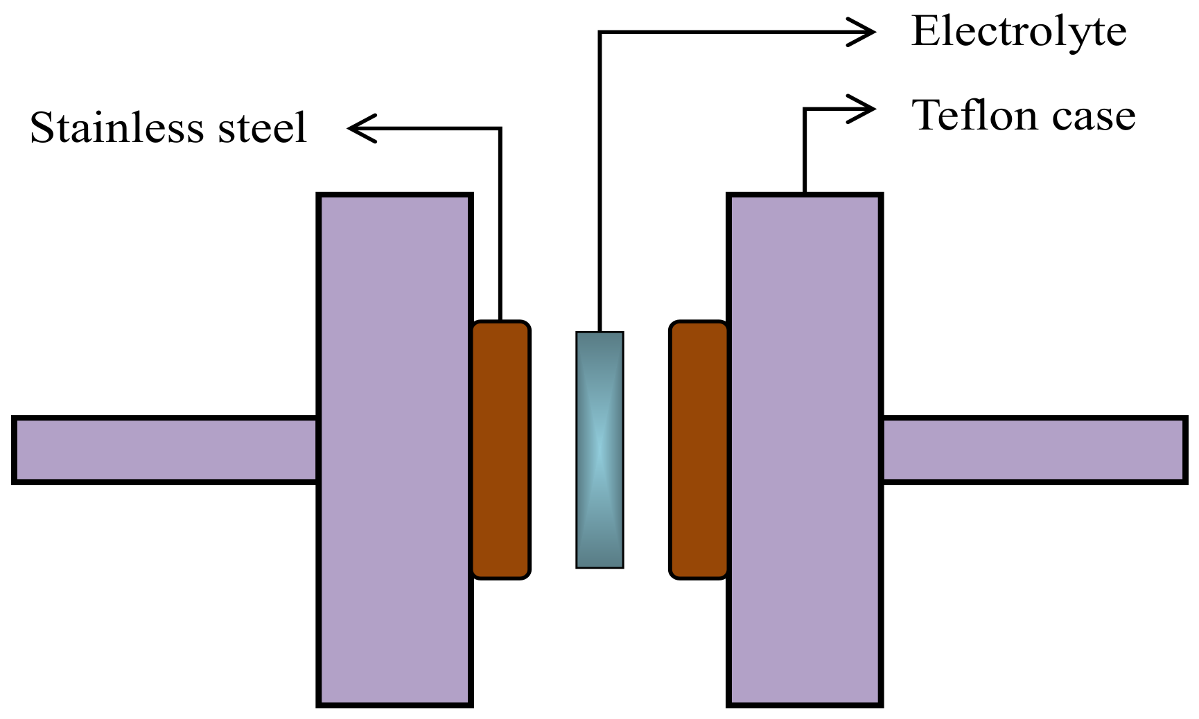
2.2. Impedance, Morphology, and Fourier Transform Infrared Analyses
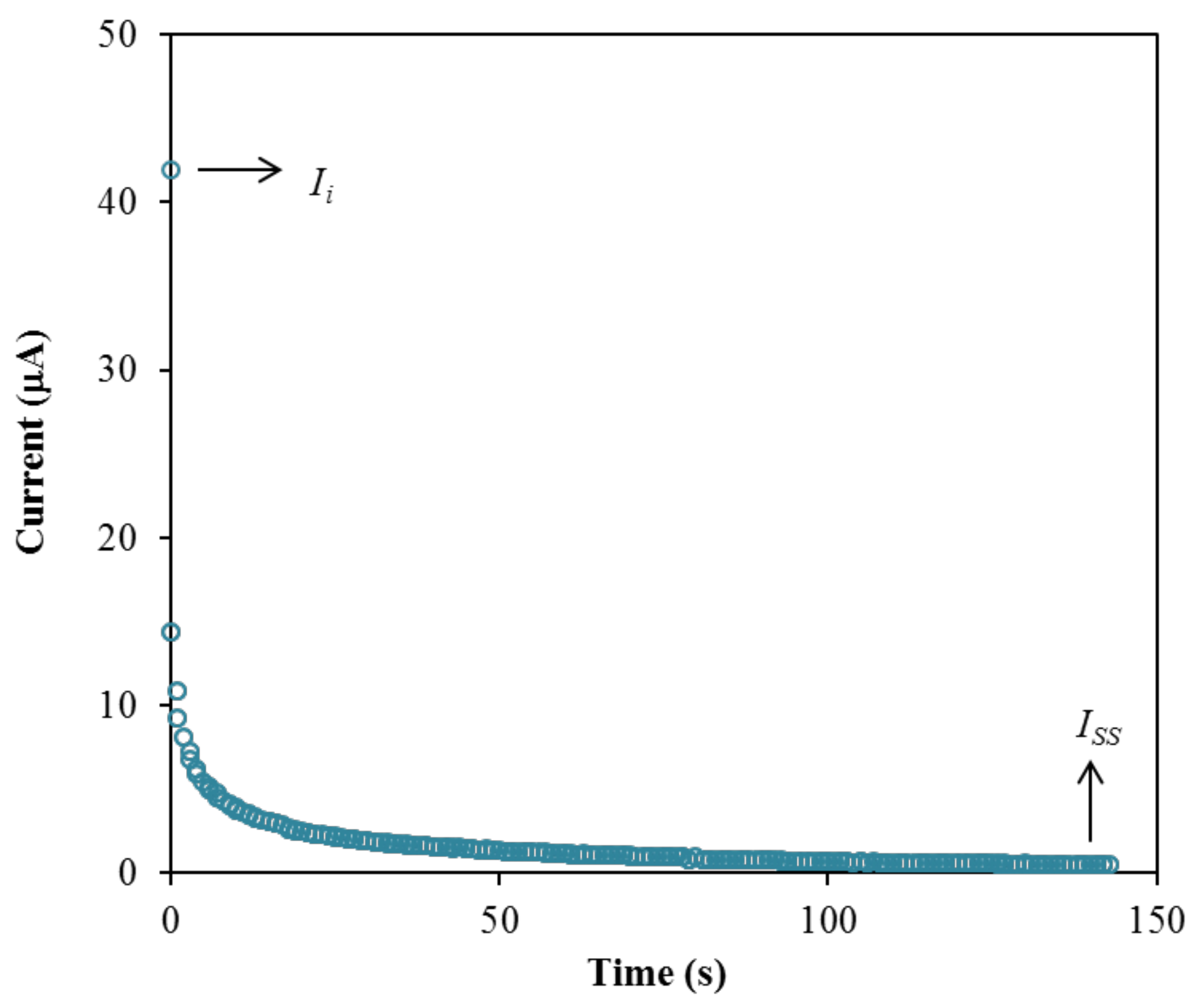
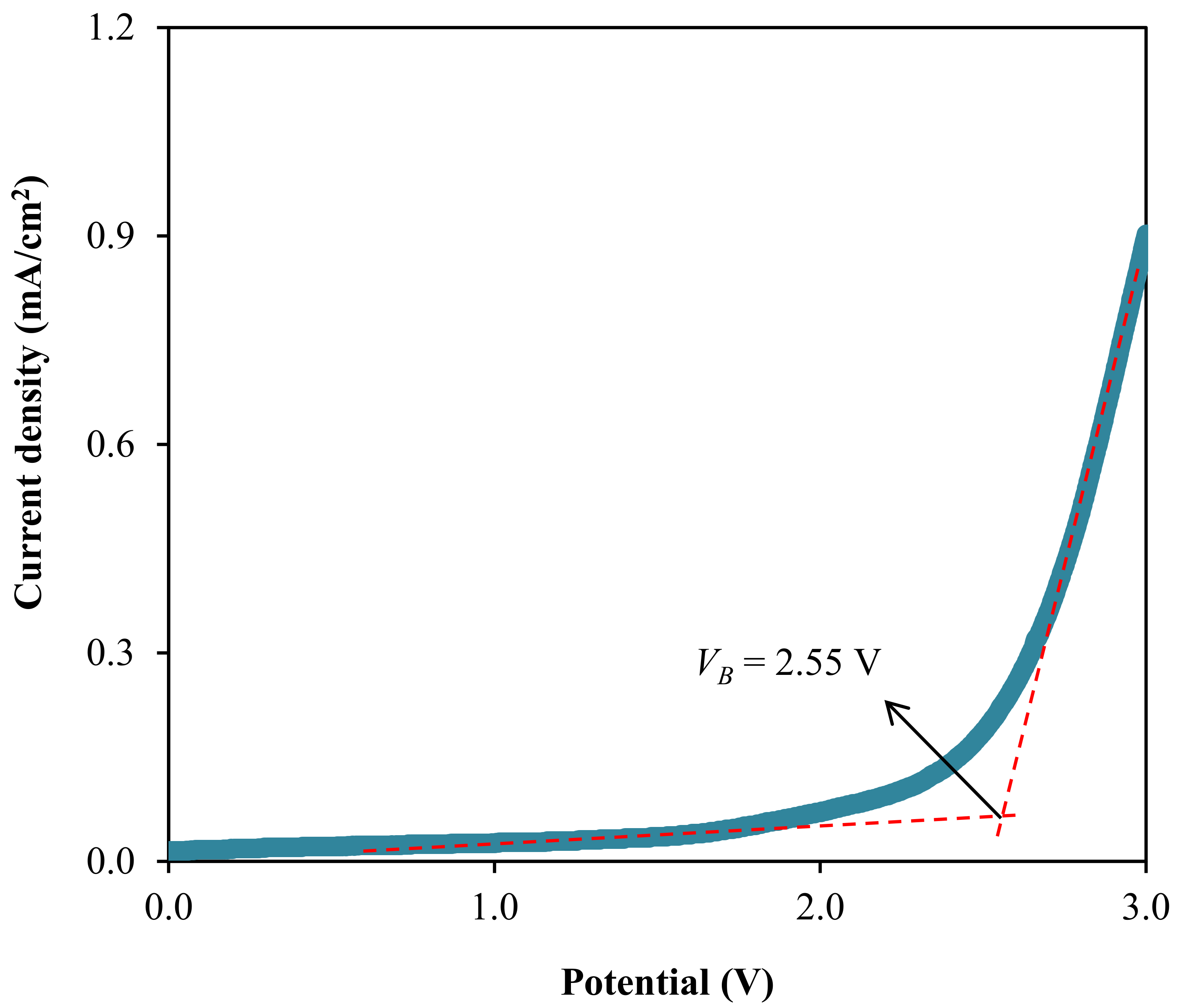
2.3. Transference Number Measurement (TNM) and Linear Sweep Voltammetry (LSV) Measurement
3. Result and Discussion
3.1. Ionic Conductivity Studies
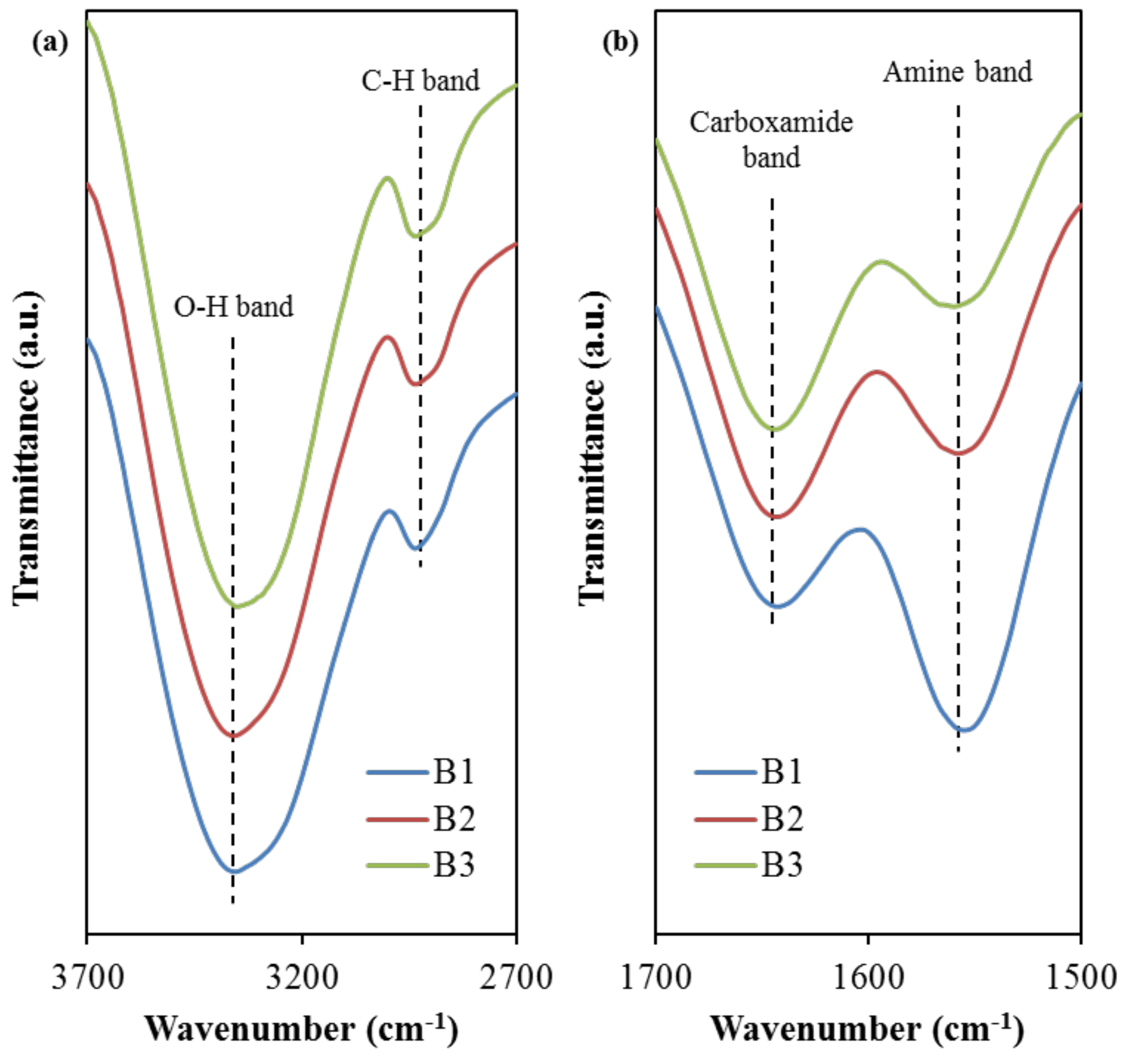
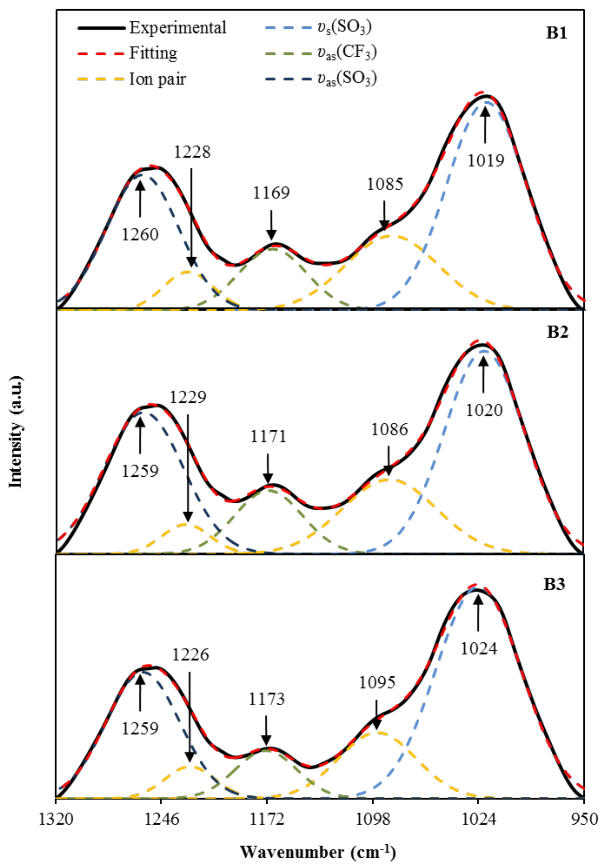
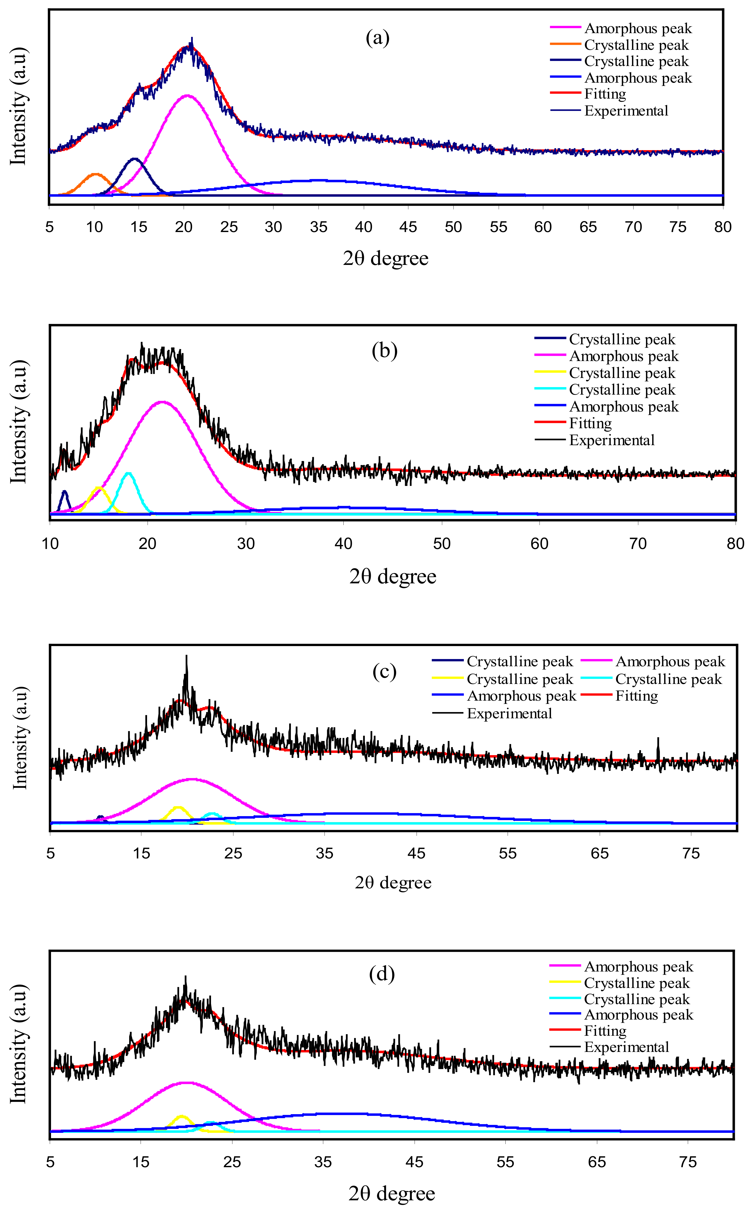
3.2. FTIR and XRD Studies
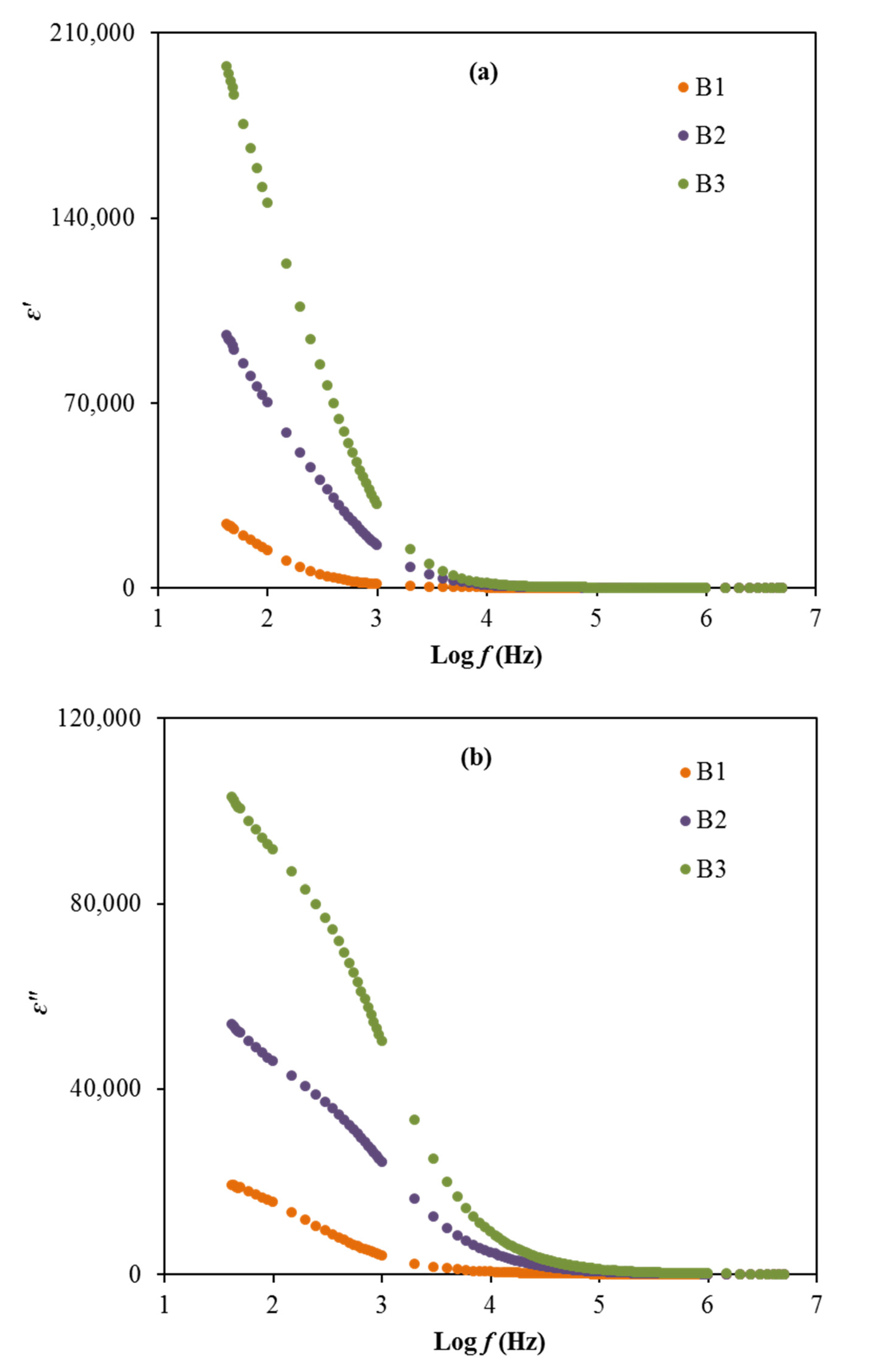
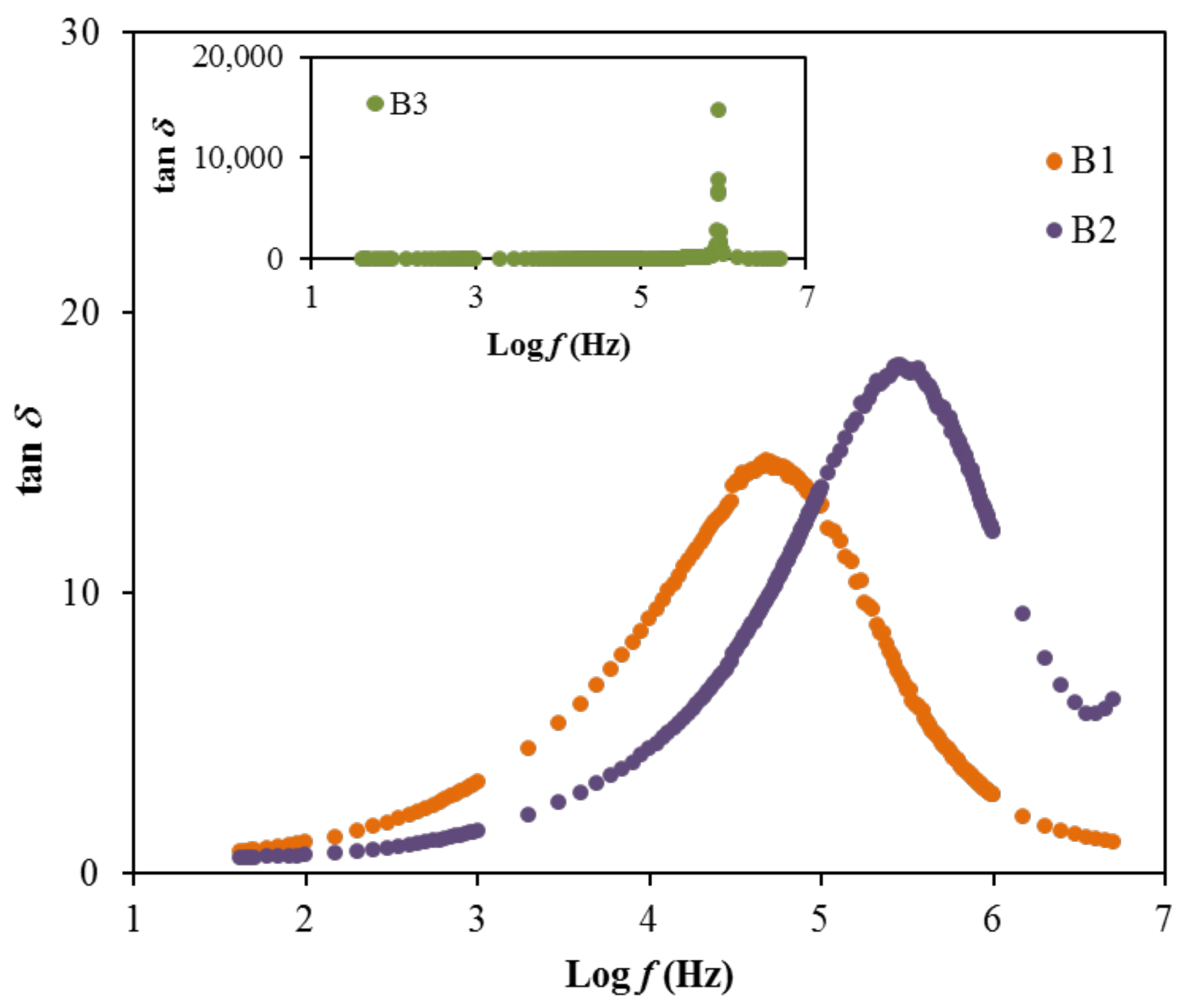
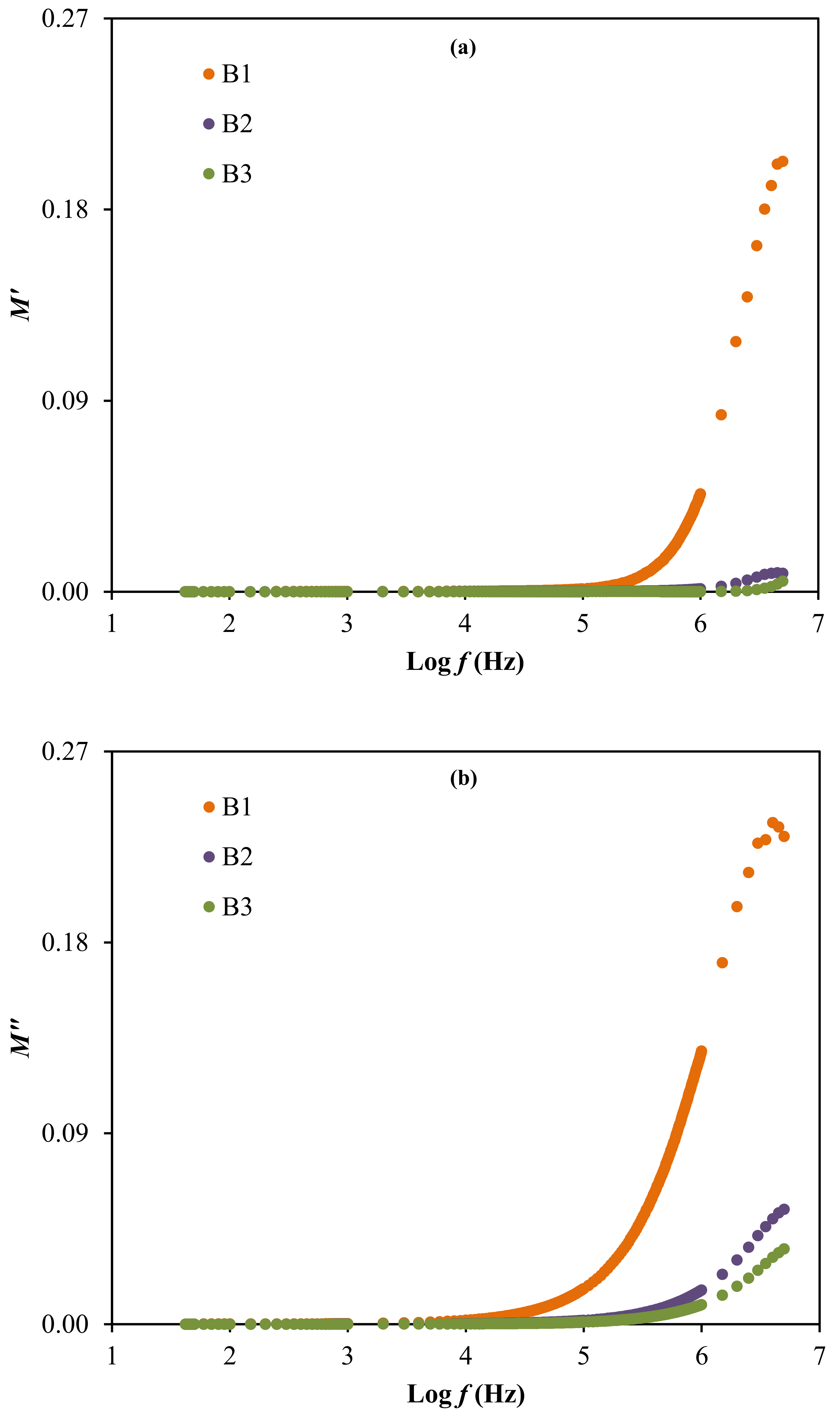
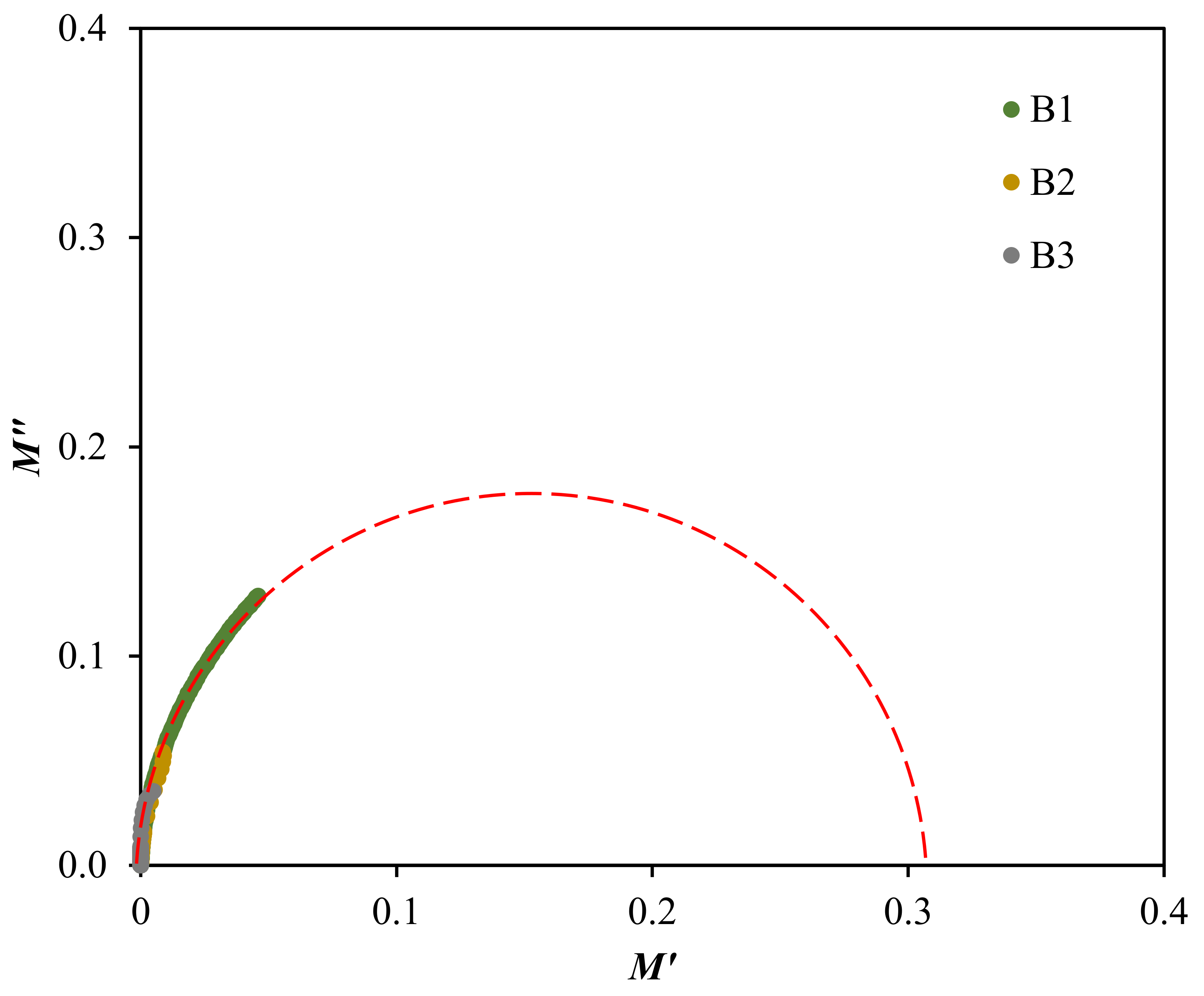
3.3. Dielectric and Electric Modulus Analysis
3.4. Electrochemical Investigation
4. Conclusions
Author Contributions
Funding
Institutional Review Board Statement
Informed Consent Statement
Data Availability Statement
Acknowledgments
Conflicts of Interest
References
- Yusof, Y.M.; Shukur, M.F.; Illias, H.A.; Kadir, M.F.Z. Conductivity and electrical properties of corn starch-chitosan blend biopolymer electrolyte incorporated with ammonium iodide. Phys. Scr. 2014, 89, 1–10. [Google Scholar] [CrossRef]
- Kim, W.J.; Kim, D.W. Sulfonated poly(ether ether ketone) membranes for electric double layer capacitors. Electrochim. Acta 2008, 53, 4331–4335. [Google Scholar] [CrossRef]
- Hu, X.; Muchakayala, R.; Song, S.; Wang, J.; Chen, J.; Tan, M. Synthesis and optimization of new polymeric ionic liquid poly(diallydimethylammonium) bis(trifluoromethane sulfonyl)imde based gel electrolyte films. Int. J. Hydrogen Energy 2018, 43, 3741–3749. [Google Scholar] [CrossRef]
- Zhang, B.; Liang, J.; Xu, C.L.; Wei, B.Q.; Ruan, D.B.; Wu, D.H. Electric double-layer capacitors using carbon nanotube electrodes and organic electrolyte. Mater. Lett. 2001, 51, 539–542. [Google Scholar] [CrossRef]
- Chang, J.; Park, M.; Ham, D.; Ogale, S.B.; Mane, R.S.; Han, S.H. Liquid-Phase synthesized mesoporous electrochemical supercapacitors of nickel hydroxide. Electrochim. Acta 2008, 53, 5016–5021. [Google Scholar] [CrossRef]
- McBreen, J.; Lee, H.S.; Yang, X.Q.; Sun, X. New approaches to the design of polymer and liquid electrolytes for lithium batteries. J. Power Sources 2000, 89, 163–167. [Google Scholar] [CrossRef]
- Mahendran, O.; Chen, S.Y.; Chen-Yang, Y.W.; Lee, J.Y.; Rajendran, S. Investigations on PMMA-PVdF polymer blend electrolyte with esters of dibenzoic acids as plasticizers. Ionics 2005, 11, 251–258. [Google Scholar] [CrossRef]
- Staiti, P.; Minutoli, M.; Lufrano, F. All solid electric double layer capacitors based on Nafion ionomer. Electrochim. Acta 2002, 47, 2795–2800. [Google Scholar] [CrossRef]
- Singh, R.; Singh, P.K.; Singh, V.; Bhattacharya, B. Quantitative analysis of ion transport mechanism in biopolymer electrolyte. Opt. Laser Technol. 2019, 113, 303–309. [Google Scholar] [CrossRef]
- Kumar, S.; Prajapati, G.K.; Saroj, A.L.; Gupta, P.N. Structural, electrical and dielectric studies of nano-composite polymer blend electrolyte films based on (70–x) PVA–x PVP–NaI–SiO2. Phys. B Condens. Matter 2019, 554, 158–164. [Google Scholar] [CrossRef]
- Singh, R.; Bhattacharya, B.; Gupta, M.; Rahul; Khan, Z.H.; Tomar, S.K.; Singh, V.; Singh, P.K. Electrical and structural properties of ionic liquid doped polymer gel electrolyte for dual energy storage devices. Int. J. Hydrogen Energy 2017, 42, 14602–14607. [Google Scholar] [CrossRef]
- Moniha, V.; Alagar, M.; Selvasekarapandian, S.; Sundaresan, B.; Boopathi, G. Conductive bio-polymer electrolyte iota-carrageenan with ammonium nitrate for application in electrochemical devices. J. Non Cryst. Solids 2018, 481, 424–434. [Google Scholar] [CrossRef]
- Riess, I. Polymeric mixed ionic electronic conductors. Solid State Ion. 2000, 136–137, 1119–1130. [Google Scholar] [CrossRef]
- Parameswaran, V.; Nallamuthu, N.; Devendran, P.; Nagarajan, E.R.; Manikandan, A. Electrical conductivity studies on Ammonium bromide incorporated with Zwitterionic polymer blend electrolyte for battery application. Phys. B Condens. Matter 2017, 515, 89–98. [Google Scholar] [CrossRef]
- Bakar, N.Y.A.; Muhamaruesa, N.H.M.; Aniskari, N.A.B.; Isa, M.I.N.M. Electrical studies of carboxy methycellulose-chitosan blend biopolymer doped dodecyltrimethyl ammonium bromide solid electrolytes. Am. J. Appl. Sci. 2015, 12, 40–46. [Google Scholar] [CrossRef]
- Samsudin, A.; Isa, M. Structural and electrical properties of carboxy methylcellulose-dodecyltrimethyl ammonium bromide-based biopolymer electrolytes system. Int. J. Polym. Mater. Polym. Biomater. 2012, 61, 30–40. [Google Scholar] [CrossRef]
- Samsudin, A.S.; Isa, M.I.N. Ion conducting mechanism of carboxy methylcellulose doped with ionic dopant salicylic acid based solid polymer electrolytes. Int. J. Appl. Sci. Technol. 2012, 2, 113–121. [Google Scholar]
- Aziz, S.B.; Hamsan, M.H.; Kadir, M.F.Z.; Woo, H.J. Design of polymer blends based on chitosan: POZ with improved dielectric constant for application in polymer electrolytes and flexible electronics. Adv. Polym. Technol. 2020, 2020, 1–10. [Google Scholar] [CrossRef]
- Stepniak, I.; Galinski, M.; Nowacki, K.; Wysokowski, M.; Jakubowska, P.; Bazhenov, V.V.; Leisegang, T.; Ehrlich, H.; Jesionowski, T. A novel chitosan/sponge chitin origin material as a membrane for supercapacitors-preparation and characterization. RSC Adv. 2016, 6, 4007–4013. [Google Scholar] [CrossRef]
- Zulkifli, A.M.; Said, N.I.A.M.; Aziz, S.B.; Hisham, S.; Shah, S.; Bakar, A.A.; Abidin, Z.H.Z.; Tajuddin, H.A.; Sulaiman, L.; Brza, M.A.; et al. Electrochemical characteristics of phthaloyl chitosan based gel polymer electrolyte for dye sensitized solar cell application. Int. J. Electrochem. Sci. 2020, 15, 7434–7447. [Google Scholar] [CrossRef]
- Khiar, A.S.A.; Puteh, R.; Arof, A.K. Characterizations of chitosan-ammonium triflate (NH4CF3SO3) complexes by FTIR and impedance spectroscopy. Phys. Status Solidi Appl. Mater. Sci. 2006, 203, 534–543. [Google Scholar] [CrossRef]
- Sarwat, F.; Ahmed, N.; Aman, A.; Qader, S.A.U. Optimization of growth conditions for the isolation of dextran producing Leuconostoc spp. from indigenous food sources. Pak. J. Pharm. Sci. 2013, 26, 793–797. [Google Scholar] [PubMed]
- Vettori, M.H.P.B.; Franchetti, S.M.M.; Contiero, J. Structural characterization of a new dextran with a low degree of branching produced by Leuconostoc mesenteroides FT045B dextransucrase. Carbohydr. Polym. 2012, 88, 1440–1444. [Google Scholar] [CrossRef]
- Aziz, S.B.; Hamsan, M.H.; Kadir, M.F.Z.; Karim, W.O.; Abdullah, R.M. Development of polymer blend electrolyte membranes based on chitosan: Dextran with high ion transport properties for EDLC application. Int. J. Mol. Sci. 2019, 20, 3369. [Google Scholar] [CrossRef]
- Telegeev, G.; Kutsevol, N.; Chumachenko, V.; Naumenko, A.; Telegeeva, P.; Filipchenko, S.; Harahuts, Y. Dextran-Polyacrylamide as Matrices for Creation of Anticancer Nanocomposite. Int. J. Polym. Sci. 2017, 2017, 4929857. [Google Scholar] [CrossRef]
- Hamsan, H.M.; Aziz, S.; Kadir, M.F.Z.; Brza, M.A.; Karim, W. The study of EDLC device fabricated from plasticized magnesium ion conducting chitosan based polymer electrolyte. Polym. Test. 2020, 106714. [Google Scholar] [CrossRef]
- Anilkumar, K.M.; Jinisha, B.; Manoj, M.; Jayalekshmi, S. Poly(ethylene oxide) (PEO)—Poly(vinyl pyrrolidone) (PVP) blend polymer based solid electrolyte membranes for developing solid state magnesium ion cells. Eur. Polym. J. 2017, 89, 249–262. [Google Scholar] [CrossRef]
- Gong, S.D.; Huang, Y.; Cao, H.J.; Lin, Y.H.; Li, Y.; Tang, S.H.; Wang, M.S.; Li, X. A green and environment-friendly gel polymer electrolyte with higher performances based on the natural matrix of lignin. J. Power Sources 2016, 307, 624–633. [Google Scholar] [CrossRef]
- Farah, N.; Ng, H.M.; Numan, A.; Liew, C.W.; Latip, N.A.A.; Ramesh, K.; Ramesh, S. Solid polymer electrolytes based on poly(vinyl alcohol) incorporated with sodium salt and ionic liquid for electrical double layer capacitor. Mater. Sci. Eng. B Solid State Mater. Adv. Technol. 2019, 251, 1–9. [Google Scholar] [CrossRef]
- Poy, S.Y.; Bashir, S.; Omar, F.S.; Saidi, N.M.; Farhana, N.K.; Sundararajan, V.; Ramesh, K.; Ramesh, S. Poly (1-vinylpyrrolidone-co-vinyl acetate) (PVP-co-VAc) based gel polymer electrolytes for electric double layer capacitors (EDLC). J. Polym. Res. 2020, 27, 1–10. [Google Scholar] [CrossRef]
- Aziz, S.B.; Mamand, S.M. The Study of dielectric properties and conductivity relaxation of ion conducting chitosan: NaTf based solid electrolyte. Int. J. Electrochem. Sci. 2018, 13, 10274–10288. [Google Scholar] [CrossRef]
- Liang, S.; Huang, Q.; Liu, L.; Yam, K.I. Microstructure and molecular interaction in glycerol plasticized chitosan/poly(vinyl alcohol) blending films. Macromol. Chem. Phys. 2009, 210, 832–839. [Google Scholar] [CrossRef]
- Yusof, Y.M.; Kadir, M.F.Z. Electrochemical characterizations and the effect of glycerol in biopolymer electrolytes based on methylcellulose-potato starch blend. Mol. Cryst. Liq. Cryst. 2016, 627, 220–233. [Google Scholar] [CrossRef]
- Kadir, M.; Salleh, N.; Hamsan, M.; Aspanut, Z.; Majid, N.; Shukur, M. Biopolymeric electrolyte based on glycerolized methyl cellulose with NH4Br as proton source and potential application in EDLC. Ionics (Kiel) 2018, 24, 1651–1662. [Google Scholar] [CrossRef]
- Shukur, M.F.; Hamsan, M.H.; Kadir, M.F.Z. Investigation of plasticized ionic conductor based on chitosan and ammonium bromide for EDLC application. Mater. Today Proc. 2019, 17, 490–498. [Google Scholar] [CrossRef]
- Asnawi, A.S.F.M.; Aziz, S.B.; Nofal, M.; Abdulwahid, R.T.; Kadir, M.F.Z.; Hamsan, M.H.; Brza, M.A.; Yusof, Y.M.; Abdilwahid, R.T. Glycerolized Li+ Ion conducting chitosan-based polymer electrolyte for energy storage EDLC device applications with relatively high energy density. Polymers 2020, 12, 1433. [Google Scholar] [CrossRef]
- Kadir, M.; Hamsan, M. Green electrolytes based on dextran-chitosan blend and the effect of NH4SCN as proton provider on the electrical response studies. Ionics (Kiel) 2018, 24, 2379–2398. [Google Scholar] [CrossRef]
- Brza, M.A.; Aziz, S.B.; Anuar, H.; Ali, F.; Hamsan, M.H.; Kadir, M.F.Z. Metal framework as a novel approach for the fabrication of electric double layer capacitor device with high energy density using plasticized poly(vinyl alcohol): Ammonium thiocyanate based polymer electrolyte. Arab. J. Chem. 2020, 13, 7247–7263. [Google Scholar] [CrossRef]
- Kumar, M.; Tiwari, T.; Chauhan, J.K.; Srivastava, N. Erratum: UnderstanDing the ion dynamics and relaxation behavior from impedance spectroscopy of NaI doped Zwitterionic polymer system. Mater. Res. Express 2014, 1, 049601. [Google Scholar] [CrossRef]
- Gohel, K.; Kanchan, D.K. Ionic conductivity and relaxation studies in PVDF-HFP:PMMA-based gel polymer blend electrolyte with LiClO4 salt. J. Adv. Dielectr. 2018, 8, 1850005. [Google Scholar] [CrossRef]
- Misenan, M.; Khiar, A. Conductivity, dielectric and modulus studies of methylcellulose-NH4TF polymer. Eurasian J. Biol. Chem. Sci. J. 2018, 1, 59–62. [Google Scholar]
- Teo, L.P.; Buraidah, M.H.; Nor, A.F.M.; Majid, S.R. Conductivity and dielectric studies of Li2SnO3. Ionics (Kiel) 2012, 18, 655–665. [Google Scholar] [CrossRef]
- Aziz, S.B.; Marif, R.B.; Brza, M.A.; Hamsan, M.H.; Kadir, M.F.Z. Employing of Trukhan model to estimate ion transport parameters in PVA based solid polymer electrolyte. Polymers 2019, 11, 1694. [Google Scholar] [CrossRef] [PubMed]
- Awasthi, P.; Das, S. Reduced electrode polarization at electrode and analyte interface in impedance spectroscopy using carbon paste and paper. Rev. Sci. Instrum. 2019, 90, 124103. [Google Scholar] [CrossRef] [PubMed]
- Lee, D.K.; Allcock, H.R. The effects of cations and anions on the ionic conductivity of poly[bis(2-(2-methoxyethoxy)ethoxy)phosphazene] doped with lithium and magnesium salts of trifluoromethanesulfonate and bis(trifluoromethanesulfonyl)imidate. Solid State Ion. 2010, 181, 1721–1726. [Google Scholar] [CrossRef]
- Marf, A.S.; Aziz, S.B.; Abdullah, R.M. Plasticized H+ ion-conducting PVA:CS-based polymer blend electrolytes for energy storage EDLC application. J. Mater. Sci. Mater. Electron. 2020, 1–15. [Google Scholar] [CrossRef]
- Aziz, S.B.; Brza, M.A.; Brevik, I.; Hafiz, M.H.; Asnawi, A.S.F.M.; Yusof, Y.M.; Abdulwahid, R.T.; Kadir, M.F.Z. Blending and characteristics of electrochemical double-layer capacitor device assembled from plasticized proton ion conducting chitosan: Dextran: NH4PF6 polymer electrolytes. Polymers (Basel) 2020, 12, 2103. [Google Scholar]
- Brza, M.A.; Aziz, B.S.; Anuar, H.; Dannoun, E.M.A.; Ali, F.; Abdulwahid, R.T.; Kadir, M.F.Z. The study of EDLC device with high electrochemical performance fabricated from proton ion conducting PVA-Based polymer composite electrolytes plasticized with glycerol. Polymers 2020, 12, 1896. [Google Scholar] [CrossRef]
- Hamsan, M.H.; Shukur, M.F.; Kadir, M.F.Z. NH4NO3 as charge carrier contributor in glycerolized potato starch-methyl cellulose blend-based polymer electrolyte and the application in electrochemical double-layer capacitor. Ionics 2017, 23, 3429–3453. [Google Scholar] [CrossRef]
- Aziz, S.B.; Abdullah, R.M. Crystalline and amorphous phase identification from the tanδ relaxation peaks and impedance plots in polymer blend electrolytes based on [CS:AgNt]x:PEO(x-1) (10 ≤ x ≤ 50). Electrochim. Acta 2018, 285, 30–46. [Google Scholar] [CrossRef]
- Mobarak, N.N.; Ahmad, A.; Abdullah, M.P.; Ramli, N.; Rahman, M.Y.A. Conductivity enhancement via chemical modification of chitosan based green polymer electrolyte. Electrochim. Acta 2013, 92, 161–167. [Google Scholar] [CrossRef]
- Aziz, S.B.; Brza, M.A.; Hamsan, M.H.; Kadir, M.F.Z.; Muzakir, S.K.; Abdulwahid, R.T. Effect of ohmic-drop on electrochemical performance of EDLC fabricated from PVA: Dextran: NH4I based polymer blend electrolytes. J. Mater. Res. Technol. 2020, 9, 3734–3745. [Google Scholar] [CrossRef]
- Yusof, Y.M.; Illias, H.A.; Kadir, M.F.Z. Incorporation of NH4Br in PVA-chitosan blend-based polymer electrolyte and its effect on the conductivity and other electrical properties. Ionics (Kiel) 2014, 20, 1235–1245. [Google Scholar] [CrossRef]
- Salleh, N.S.; Aziz, S.B.; Aspanut, Z.; Kadir, M.F.Z. Electrical impedance and conduction mechanism analysis of biopolymer electrolytes based on methyl cellulose doped with ammonium iodide. Ionics (Kiel) 2016, 22, 2157–2167. [Google Scholar] [CrossRef]
- Asnawi, A.S.F.M.; Azli, A.; Hamsan, M.; Kadir, M.; Yusof, Y. Electrical and infrared spectroscopic analysis of solid polymer electrolyte based on polyethylene oxide and graphene oxide blend. Malays. J. Anal. Sci. 2020, 24, 682–697. [Google Scholar]
- Liebeck, B.M.; Hidalgo, N.; Roth, G.; Popescu, C.; Böker, A. Synthesis and characterization of methyl cellulose/keratin hydrolysate composite membranes. Polymers (Basel) 2017, 9, 91. [Google Scholar] [CrossRef]
- Aziz, S.B.; Brza, M.A.; Hamsan, H.M.; Kadir, M.F.Z.; Abdulwahid, R.T. Electrochemical characteristics of solid state double-layer capacitor constructed from proton conducting chitosan-based polymer blend electrolytes. Polym. Bull. 2020, 1–19. [Google Scholar] [CrossRef]
- Shukur, M.F.; Yusof, Y.M.; Zawawi, S.M.M.; Illias, H.A.; Kadir, M.F.Z. Conductivity and transport studies of plasticized chitosan-based proton conducting biopolymer electrolytes. Phys. Scr. 2013, T157, 1–5. [Google Scholar] [CrossRef]
- Aziz, S.B.; Hamsan, M.H.; Nofal, M.M.; Karim, W.O.; Brevik, I.; Brza, M.; Abdulwahid, R.T.; Al-Zangana, S.; Kadir, M.F. Structural, impedance and electrochemical characteristics of electrical double layer capacitor devices based on chitosan: Dextran biopolymer blend electrolytes. Polymers (Basel) 2020, 12, 1411. [Google Scholar]
- Jeya, S.; Arulsankar, A.; Abarna, S.; Sundaresan, B. Effect of ionic liquids on the electrical, structural and morphological properties of P(VdF-HFP)-NaTF electrolytes. Ionics (Kiel) 2019, 25, 5963–5977. [Google Scholar] [CrossRef]
- Ranjana, P.A.B.; Jeya, S.; Abarna, S.; Premalatha, M.; Arulsankar, A.; Sundaresan, B. Enhancement of Na+ ion conduction in polymer blend electrolyte P(VdF-HFP)—PMMA-NaTf by the inclusion of EC. J. Polym. Res. 2019, 26, 38. [Google Scholar] [CrossRef]
- Mejenom, A.A.; Hafiza, M.N.; Isa, M.I.N. X-ray diffraction and infrared spectroscopic analysis of solid biopolymer electrolytes based on dual blend carboxymethyl cellulose-chitosan doped with ammonium bromide. ASM Sci. J. 2018, 11, 37–46. [Google Scholar]
- Aniskari, N.A.B.; Mohd Isa, M.I.N. The effect of ionic charge carriers in 2-hydroxyethyl cellulose solid biopolymer electrolytes doped glycolic acid via FTIR-deconvolution technique. J. Sustain. Sci. Manag. 2017, 12, 71–79. [Google Scholar]
- Pritam; Arya, A.; Sharma, A.L. Dielectric relaxations and transport properties parameter analysis of novel blended solid polymer electrolyte for sodium-ion rechargeable batteries. J. Mater. Sci. 2019, 54, 7131–7155. [Google Scholar] [CrossRef]
- Aziz, S.B.; Abidin, Z.H.Z.; Kadir, M.F.Z. Innovative method to avoid the reduction of silver ions to silver nanoparticles in silver ion conducting based polymer electrolytes. Phys. Scr. 2015, 90, 035808. [Google Scholar] [CrossRef]
- Aziz, S.B.; Kadir, M.F.Z.; Abidin, Z.H.Z. Structural, morphological and electrochemical impedance study of CS: LiTf based solid polymer electrolyte: Reformulated Arrhenius equation for ion transport study. Int. J. Electrochem. Sci. 2016, 11, 9228–9244. [Google Scholar] [CrossRef]
- Hamsan, M.H.; Shukur, M.F.; Aziz, S.B.; Kadir, M.F.Z. Dextran from Leuconostoc mesenteroides-doped ammonium salt-based green polymer electrolyte. Bull. Mater. Sci. 2019, 42, 57. [Google Scholar] [CrossRef]
- Aziz, S.B.; Abidin, Z.H.Z.; Arof, A.K. Effect of silver nanoparticles on the DC conductivity in chitosan-silver triflate polymer electrolyte. Phys. B 2010, 405, 4429–4433. [Google Scholar] [CrossRef]
- Yusuf, S.N.F.; Azzahari, A.D.; Yahya, R.; Majid, S.R.; Careem, M.A.; Arof, A.K. From crab shell to solar cell: A gel polymer electrolyte based on N-phthaloylchitosan and its application in dye-sensitized solar cells. RSC Adv. 2016, 6, 27714–27724. [Google Scholar] [CrossRef]
- Malathi, J.; Kumaravadivel, M.; Brahmanandhan, G.M.; Hema, M.; Baskaran, R.; Selvasekarapandian, S. Structural, thermal and electrical properties of PVA-LiCF3SO3 polymer electrolyte. J. Non Cryst. Solids 2010, 356, 2277–2281. [Google Scholar] [CrossRef]
- Aziz, S.B. Role of dielectric constant on ion transport: Reformulated Arrhenius equation. Adv. Mater. Sci. Eng. 2016, 2016, 11. [Google Scholar] [CrossRef]
- Wan, Y.; Creber, K.A.M.; Peppley, B.; Bui, V.T. Synthesis, characterization and ionic conductive properties of phosphorylated chitosan membranes. Macromol. Chem. Phys. 2003, 204, 850–858. [Google Scholar] [CrossRef]
- Smitha, B.; Sridhar, S.; Khan, A.A. Chitosan-Sodium alginate polyion complexes as fuel cell membranes. Eur. Polym. J. 2005, 4, 1859–1866. [Google Scholar] [CrossRef]
- Mohamed, A.S.; Shukur, M.F.; Kadir, M.F.Z.; Yusof, Y.M. Ion conduction in chitosan-starch blend based polymer electrolyte with ammonium thiocyanate as charge provider. J. Polym. Res. 2020, 27, 149. [Google Scholar] [CrossRef]
- Rani, M.S.A.; Ahmad, A.; Mohamed, N.S. A comprehensive investigation on electrical characterization and ionic transport properties of cellulose derivative from kenaf fibre-based biopolymer electrolytes. Polym. Bull. 2018, 75, 5061–5074. [Google Scholar] [CrossRef]
- Aziz, S.B.; Abdullah, R.M.; Kadir, M.F.Z.; Ahmed, H.M. Non suitability of silver ion conducting polymer electrolytes based on chitosan mediated by barium titanate (BaTiO3) for electrochemical device applications. Electrochim. Acta 2019, 296, 494–507. [Google Scholar] [CrossRef]
- Ramly, K.; Isa, M.I.N.; Khiar, A.S.A. Conductivity and dielectric behaviour studies of starch/PEO+ x wt-%NH4NO3 polymer electrolyte. Mater. Res. Innov. 2011, 15, s82–s85. [Google Scholar] [CrossRef]
- Pawlicka, A.; Tavares, F.C.; Dörr, D.S.; Cholant, C.M.; Ely, F.; Santos, M.J.L.; Avellaneda, C.O. Dielectric behavior and FTIR studies of xanthan gum-based solid polymer electrolytes. Electrochim. Acta 2019, 305, 232–239. [Google Scholar] [CrossRef]
- Marf, A.S.; Abdullah, R.M.; Aziz, S.B. Structural, morphological, electrical and electrochemical properties of PVA: CS-Based proton-conducting polymer blend electrolytes. Membranes (Basel) 2020, 10, 71. [Google Scholar] [CrossRef]
- Aziz, S.B.; Abdullah, R.M.; Rasheed, M.A.; Ahmed, H.M. Role of ion dissociation on DC conductivity and silver nanoparticle formation in PVA: AgNt based polymer electrolytes: Deep insights to ion transport mechanism. Polymers 2017, 9, 338. [Google Scholar] [CrossRef]
- Woo, H.J.; Majid, S.R.; Arof, A.K. Dielectric properties and morphology of polymer electrolyte based on poly(ε-caprolactone) and ammonium thiocyanate. Mater. Chem. Phys. 2012, 134, 755–761. [Google Scholar] [CrossRef]
- Idris, N.H.; Senin, H.B.; Arof, A.K. Dielectric spectra of LiTFSI-doped chitosan/PEO blends. Ionics (Kiel) 2007, 13, 213–217. [Google Scholar] [CrossRef]
- Sengwa, R.J.; Dhatarwal, P. Predominantly chain segmental relaxation dependent ionic conductivity of multiphase semicrystalline PVDF/PEO/LiClO4 solid polymer electrolytes. Electrochim. Acta 2020, 338, 135890. [Google Scholar] [CrossRef]
- Ahmed, H.T.; Jalal, V.J.; Tahir, D.A.; Mohamad, A.H.; Abdullah, O.G. Effect of PEG as a plasticizer on the electrical and optical properties of polymer blend electrolyte MC-CH-LiBF4 based films. Results Phys. 2019, 15, 102735. [Google Scholar] [CrossRef]
- Vahini, M.; Muthuvinayagam, M.; Isa, M.I.N. Preparation and characterization of biopolymer electrolytes based on pectin and NaNO3 for battery applications. Polym. Sci. Ser. A 2019, 61, 823–831. [Google Scholar] [CrossRef]
- Aziz, S.B.; Abdullah, O.G.; Hussein, S.A.; Ahmed, H.M. Effect of PVA blending on structural and ion transport properties of CS:AgNt-based polymer electrolyte membrane. Polymers (Basel) 2017, 9, 622. [Google Scholar] [CrossRef]
- Mustafa, M.S.; Ghareeb, H.O.; Aziz, S.B.; Brza, M.A.; Al-Zangana, S.; Hadi, J.M.; Kadir, M.F.Z. Electrochemical characteristics of glycerolized PEO-based polymer electrolytes. Membranes (Basel) 2020, 10, 116. [Google Scholar] [CrossRef]
- Saminatha Kumaran, V.; Ng, H.M.; Ramesh, S.; Ramesh, K.; Vengadaesvaran, B.; Numan, A. The conductivity and dielectric studies of solid polymer electrolytes based on poly (acrylamide-co-acrylic acid) doped with sodium iodide. Ionics (Kiel) 2018, 24, 1947–1953. [Google Scholar] [CrossRef]
- Fuzlin, A.F.; Rasali, N.M.J.; Samsudin, A.S. Effect on ammonium bromide in dielectric behavior based alginate solid biopolymer electrolytes. IOP Conf. Ser. Mater. Sci. Eng. 2018, 342, 1–8. [Google Scholar] [CrossRef]
- Singh, P.; Bharati, D.C.; Kumar, H.; Saroj, A.L. Ion transport mechanism and dielectric relaxation behavior of PVA-imidazolium ionic liquid-based polymer electrolytes. Phys. Scr. 2019, 94, 539–543. [Google Scholar] [CrossRef]
- Gohel, K.; Kanchan, D.K. Effect of PC:DEC plasticizers on structural and electrical properties of PVDF–HFP:PMMA based gel polymer electrolyte system. J. Mater. Sci. Mater. Electron. 2019, 30, 12260–12268. [Google Scholar] [CrossRef]
- Sundaramahalingam, K.; Muthuvinayagam, M.; Nallamuthu, N. AC impedance analysis of lithium ion based PEO:PVP solid polymer blend electrolytes. Polym. Sci. Ser. A 2019, 61, 565–576. [Google Scholar] [CrossRef]
- Rani, M.S.A.; Ahmad, A.; Mohamed, N.S. Influence of nano-sized fumed silica on physicochemical and electrochemical properties of cellulose derivatives-ionic liquid biopolymer electrolytes. Ionics (Kiel) 2018, 24, 807–814. [Google Scholar] [CrossRef]
- Brza, M.A.; Aziz, S.B.; Anuar, H.; Ali, F. Structural, ion transport parameter and electrochemical properties of plasticized polymer composite electrolyte based on PVA: A novel approach to fabricate high performance EDLC devices. Polym. Test. 2020, 91, 106813. [Google Scholar] [CrossRef]
- Shukur, M.F.; Ithnin, R.; Kadir, M.F.Z. Protonic transport analysis of starch-chitosan blend based electrolytes and application in electrochemical device. Mol. Cryst. Liq. Cryst. 2014, 603, 52–65. [Google Scholar] [CrossRef]
- Chai, M.N.; Isa, M.I.N. Novel proton conducting solid bio-polymer electrolytes based on carboxymethyl cellulose doped with oleic acid and plasticized with glycerol. Sci. Rep. 2016, 6, 1–7. [Google Scholar] [CrossRef]
- Basha, S.S.; Rao, M.C. Spectroscopic and electrochemical properties of (1-x) [PVA/PVP]: x [MgCl2{6H2O}] blend polymer electrolyte films. Int. J. Polym. Sci. 2018, 2018, 1–12. [Google Scholar] [CrossRef]
- Shukur, M.F.; Ithnin, R.; Kadir, M.F.Z. Ionic conductivity and dielectric properties of potato starch-magnesium acetate biopolymer electrolytes: The effect of glycerol and 1-butyl-3-methylimidazolium chloride. Ionics (Kiel) 2016, 22, 1113–1123. [Google Scholar] [CrossRef]
- Rama Mohan, K.; Achari, V.B.S.; Rao, V.V.R.N.; Sharma, A.K. Electrical and optical properties of (PEMA/PVC) polymer blend electrolyte doped with NaClO4. Polym. Test. 2011, 30, 881–886. [Google Scholar] [CrossRef]
- Tang, J.; Muchakayala, R.; Song, S.; Wang, M.; Kumar, K.N. Effect of EMIMBF4 ionic liquid addition on the structure and ionic conductivity of LiBF4-complexed PVdF-HFP polymer electrolyte films. Polym. Test. 2016, 50, 247–254. [Google Scholar] [CrossRef]
- Monisha, S.; Mathavan, T.; Selvasekarapandian, S.; Benial, M.F.A.; Aristatil, G.; Mani, N.; Premalatha, M.; Vinoth Pandi, D. Investigation of bio polymer electrolyte based on cellulose acetate-ammonium nitrate for potential use in electrochemical devices. Carbohydr. Polym. 2017, 157, 38–47. [Google Scholar] [CrossRef] [PubMed]
- Hafiza, M.N.; Isa, M.I.N. Correlation between structural, ion transport and ionic conductivity of plasticized 2-hydroxyethyl cellulose based solid biopolymer electrolyte. J. Membr. Sci. 2020, 597, 117176. [Google Scholar] [CrossRef]
- Shamsuri, N.A.; Zaine, S.N.A.; Yusof, Y.M.; Yahya, W.Z.N.; Shukur, M.F. Effect of ammonium thiocyanate on ionic conductivity and thermal properties of polyvinyl alcohol-methylcellulose-based polymer electrolytes. Ionics (Kiel) 2020, 26, 6083–6093. [Google Scholar] [CrossRef]
- Zulkifli, A.; Saadiah, M.A.; Mazuki, N.F.; Samsudin, A.S. Characterization of an amorphous materials hybrid polymer electrolyte based on a LiNO3-doped, CMC-PVA blend for application in an electrical double layer capacitor. Mater. Chem. Phys. 2020, 253, 123312. [Google Scholar] [CrossRef]
- Aziz, S.B.; Abdullah, O.G.; Rasheed, M.A. Structural and electrical characteristics of PVA:NaTf based solid polymer electrolytes: Role of lattice energy of salts on electrical DC conductivity. J. Mater. Sci. Mater. Electron. 2017, 28, 12873–12884. [Google Scholar] [CrossRef]
- Arof, A.K.; Kufian, M.Z.; Syukur, M.F.; Aziz, M.F.; Abdelrahman, A.E.; Majid, S.R. Electrical double layer capacitor using poly(methyl methacrylate)-C4BO8Li gel polymer electrolyte and carbonaceous material from shells of mata kucing (Dimocarpus longan) fruit. Electrochim. Acta 2012, 74, 39–45. [Google Scholar] [CrossRef]
- Sampathkumar, L.; Christopher Selvin, P.; Selvasekarapandian, S.; Perumal, P.; Chitra, R.; Muthukrishnan, M. Synthesis and characterization of biopolymer electrolyte based on tamarind seed polysaccharide, lithium perchlorate and ethylene carbonate for electrochemical applications. Ionics (Kiel) 2019, 25, 1067–1082. [Google Scholar] [CrossRef]
- Liew, C.W.; Ramesh, S.; Arof, A.K. Good prospect of ionic liquid based-poly(vinyl alcohol) polymer electrolytes for supercapacitors with excellent electrical, electrochemical and thermal properties. Int. J. Hydrogen Energy 2014, 39, 2953–2963. [Google Scholar] [CrossRef]
- Shuhaimi, N.E.A.; Alias, N.A.; Majid, S.R.; Arof, A.K. Electrical double layer capacitor with proton conducting Κ-Carrageenan–Chitosan electrolytes. Funct. Mater. Lett. 2009, 1, 195–201. [Google Scholar] [CrossRef]


| Symbols | Physical Significances |
|---|---|
| SPE | Solid polymer electrolyte |
| EDLC | Electric double-layer capacitor |
| CPE | Constant phase element in F |
| Rb | Bulk resistance in Ω |
| tion | Ion transference number |
| te | Electron transference number |
| σ | DC ionic conductivity in S/cm |
| t | Thickness of the sample in cm |
| A | Area of the sample in cm2 |
| NA | Avogadro’s number |
| M | Number of moles of glycerol |
| T | Temperature in K |
| KB | Boltzmann constant in J/K |
| VTotal | Total volume of the polymer electrolytes |
| D | Diffusion coefficient of ions in cm2 s−1 |
| µ | Mobility of ions in cm2 V−1 s−1 |
| n | Number density of ions in cm−3 |
| P | Deviation from the axes |
| C | Capacitance in F |
| ω | Angular frequency in Hz |
| Co | Vacuum capacitance in F |
| ε′ | Dielectric constant |
| ε″ | Dielectric loss |
| Ii | Initial current |
| Iss | Steady state current |
| µ+ | Mobility of cations in cm2 V−1 s−1 |
| µ− | Mobility of anions in cm2 V−1 s−1 |
| D+ | Diffusion coefficient of cations in cm2 s−1 |
| D− | Diffusion coefficient of anions in cm2 s−1 |
| Glycerol (wt.%) | Designation |
|---|---|
| 12 | B1 |
| 28 | B2 |
| 42 | B3 |
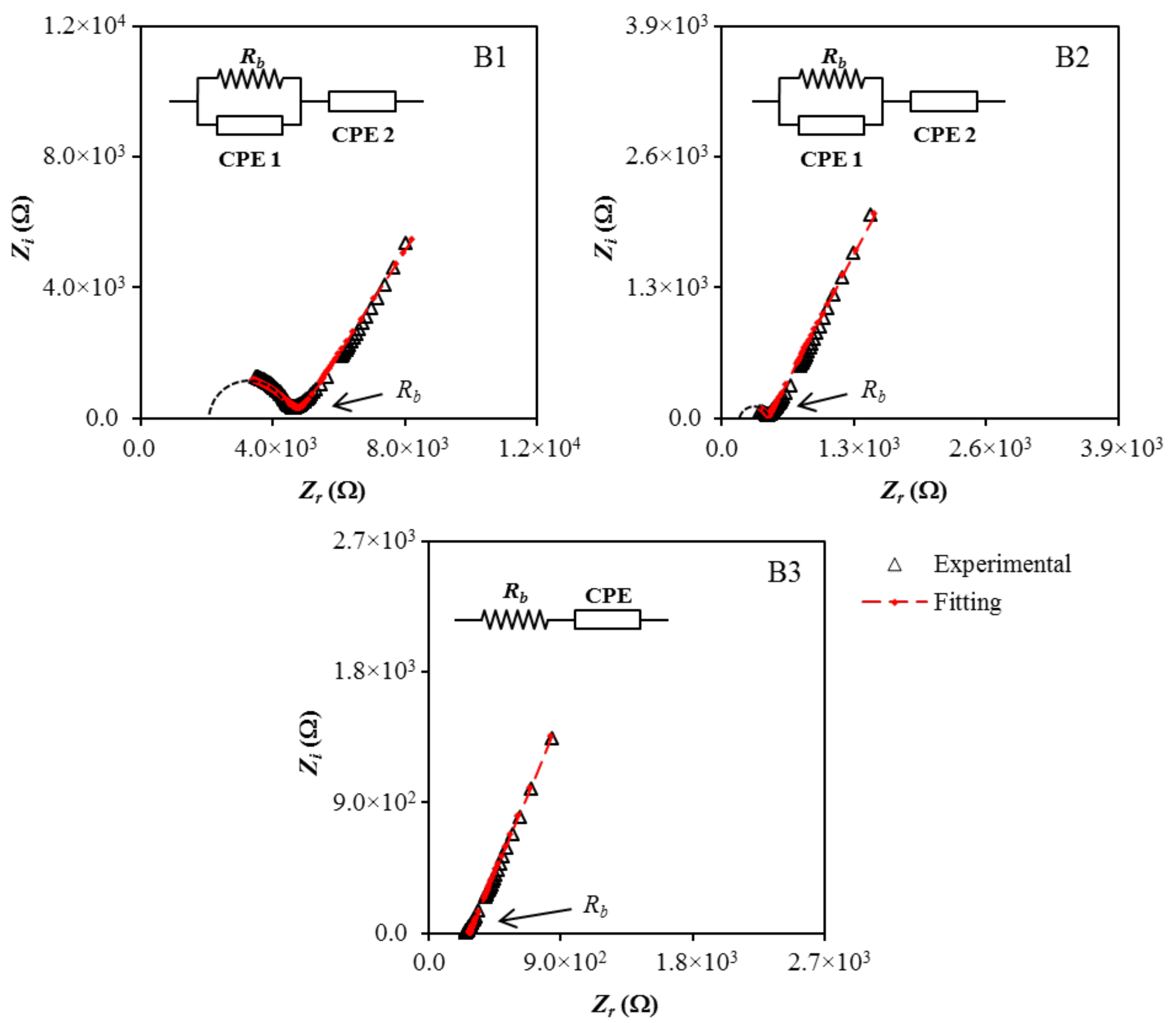
| Electrolyte | Rb (Ω) | CPE1 (F) | CPE2 (F) |
|---|---|---|---|
| B1 | (4.79 ± 1.2) × 103 | (4.00 ± 1.3) × 10−9 | (2.86 ± 0.7) × 10−6 |
| B2 | (3.21 ± 1.0) × 102 | (2.86 ± 1.1) × 10−9 | (3.70 ± 1.0) × 10−6 |
| B3 | (2.53 ± 0.8) × 102 | - | (5.41 ± 1.2) × 10−6 |
| Electrolyte | σ (S/cm) |
|---|---|
| B1 | 3.22 × 10⁻⁶ |
| B2 | 4.80 × 10⁻⁵ |
| B3 | 6.10 × 10⁻⁵ |
| Electrolyte | Number Density, n (cm−3) | Ionic Mobility, μ (cm2 V−1 s−1) | Diffusion Coefficient, D (cm2 s−1) |
|---|---|---|---|
| B1 | 2.13 × 10²² | 9.44 × 10⁻¹⁰ | 2.42 × 10⁻¹¹ |
| B2 | 8.96 × 10²² | 3.35 × 10⁻⁹ | 8.59 × 10⁻¹¹ |
| B3 | 1.02 × 10²³ | 3.75 × 10⁻⁹ | 9.61 × 10⁻¹¹ |
| Electrolyte | Degree of Crystallinity (%) |
|---|---|
| Pure CS | 15.97 |
| CS Dex | 13.85 |
| B1 | 7.96 |
| B3 | 5.52 |
| Electrolyte | tr (s) |
|---|---|
| B1 | 3.32 × 10⁻⁶ |
| B2 | 5.49 × 10⁻⁷ |
| B3 | 1.81 × 10⁻⁷ |
Publisher’s Note: MDPI stays neutral with regard to jurisdictional claims in published maps and institutional affiliations. |
© 2021 by the authors. Licensee MDPI, Basel, Switzerland. This article is an open access article distributed under the terms and conditions of the Creative Commons Attribution (CC BY) license (http://creativecommons.org/licenses/by/4.0/).
Share and Cite
Asnawi, A.S.F.M.; Aziz, S.B.; Brevik, I.; Brza, M.A.; Yusof, Y.M.; Alshehri, S.M.; Ahamad, T.; Kadir, M.F.Z. The Study of Plasticized Sodium Ion Conducting Polymer Blend Electrolyte Membranes Based on Chitosan/Dextran Biopolymers: Ion Transport, Structural, Morphological and Potential Stability. Polymers 2021, 13, 383. https://doi.org/10.3390/polym13030383
Asnawi ASFM, Aziz SB, Brevik I, Brza MA, Yusof YM, Alshehri SM, Ahamad T, Kadir MFZ. The Study of Plasticized Sodium Ion Conducting Polymer Blend Electrolyte Membranes Based on Chitosan/Dextran Biopolymers: Ion Transport, Structural, Morphological and Potential Stability. Polymers. 2021; 13(3):383. https://doi.org/10.3390/polym13030383
Chicago/Turabian StyleAsnawi, Ahmad S.F.M., Shujahadeen B. Aziz, Iver Brevik, Mohamad A. Brza, Yuhanees M. Yusof, Saad M. Alshehri, Tansir Ahamad, and M. F. Z. Kadir. 2021. "The Study of Plasticized Sodium Ion Conducting Polymer Blend Electrolyte Membranes Based on Chitosan/Dextran Biopolymers: Ion Transport, Structural, Morphological and Potential Stability" Polymers 13, no. 3: 383. https://doi.org/10.3390/polym13030383
APA StyleAsnawi, A. S. F. M., Aziz, S. B., Brevik, I., Brza, M. A., Yusof, Y. M., Alshehri, S. M., Ahamad, T., & Kadir, M. F. Z. (2021). The Study of Plasticized Sodium Ion Conducting Polymer Blend Electrolyte Membranes Based on Chitosan/Dextran Biopolymers: Ion Transport, Structural, Morphological and Potential Stability. Polymers, 13(3), 383. https://doi.org/10.3390/polym13030383