Hydrophobic Modification of Nanocellulose via a Two-Step Silanation Method

 ,
,
Abstract

1. Introduction
2. Experimental Section
2.1. Materials
2.2. Production of NCC
2.3. Preparation of KH560-NCC Powders
2.4. Preparation of C12-KH560-NCC Powders
2.5. Fourier Transform Infrared (FTIR) Spectroscopy
2.6. X-ray Photoelectron Spectroscopy (XPS)
2.7. HCl–acetone Titration
2.8. X-ray Diffraction (XRD)
2.9. Thermogravimetric Analysis (TGA)
2.10. Atomic Force Microscopy (AFM)
2.11. Water Contact Angle (WCA) Measurement
3. Results and Discussion
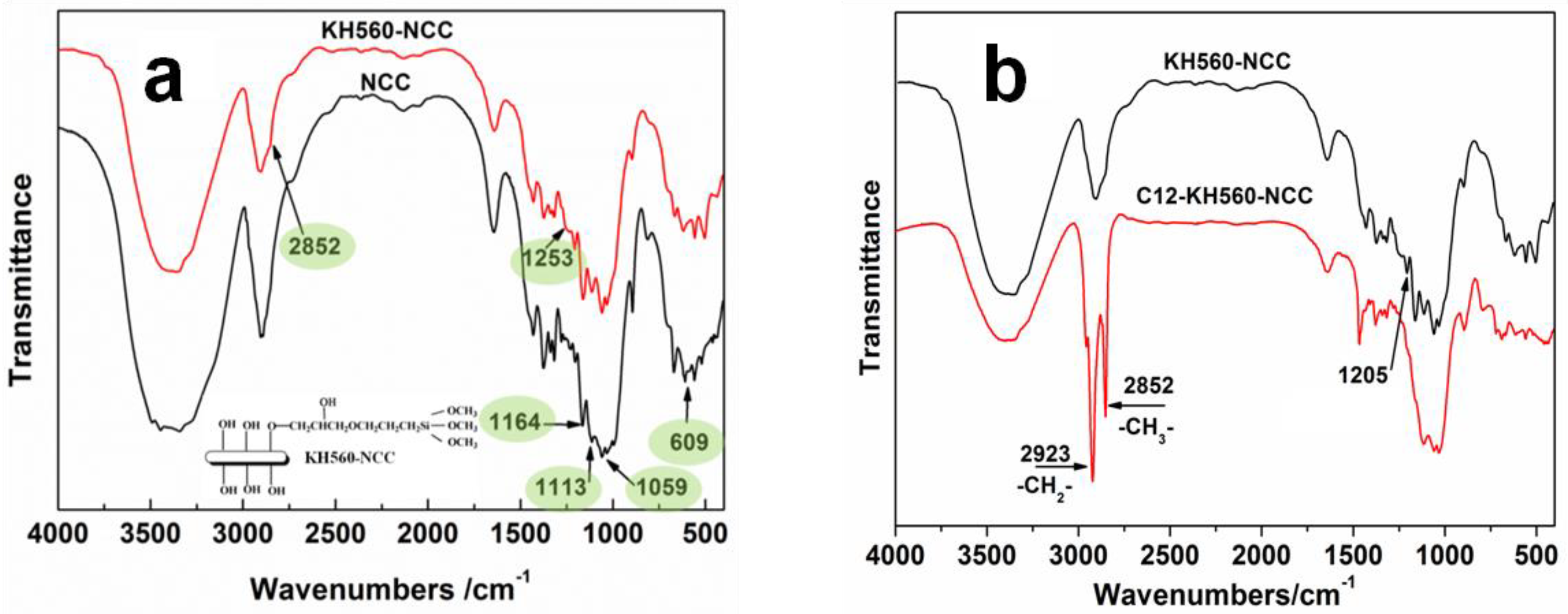
3.1. Fourier Transform Infrared (FTIR) Characterization
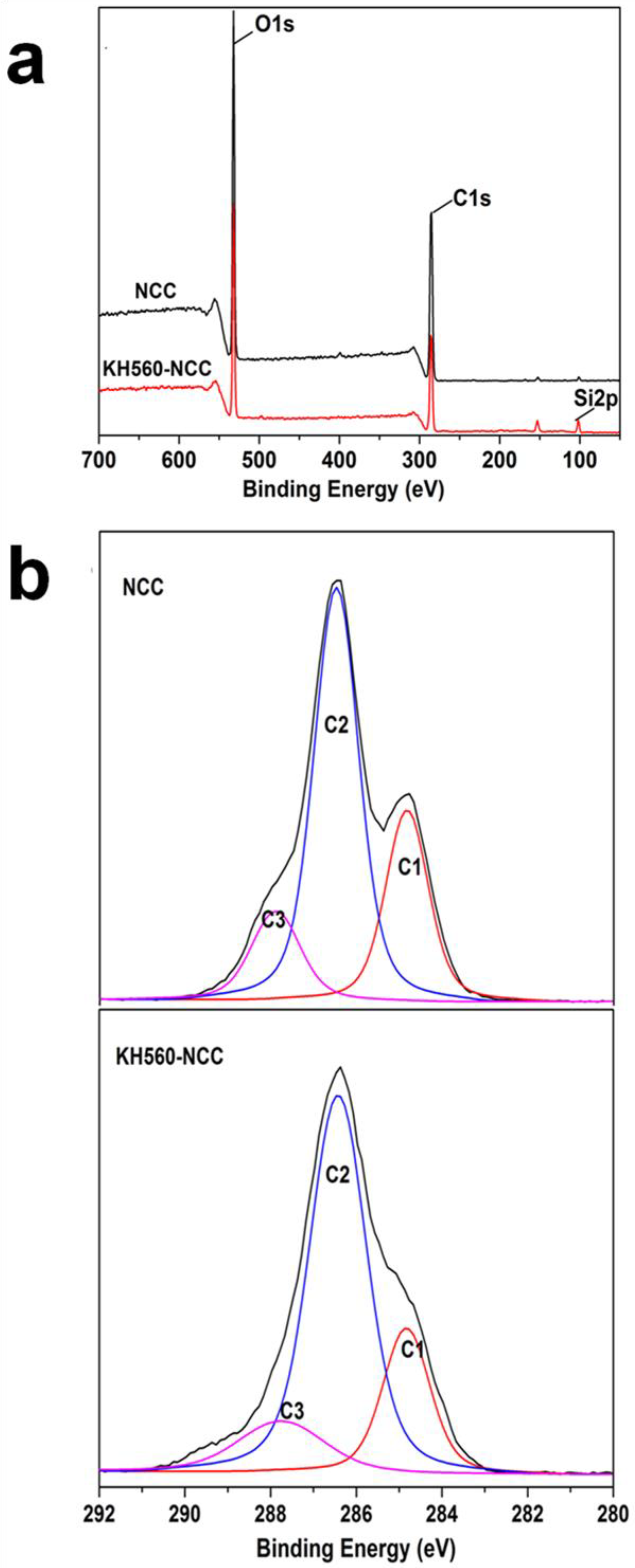
3.2. XPS Analysis
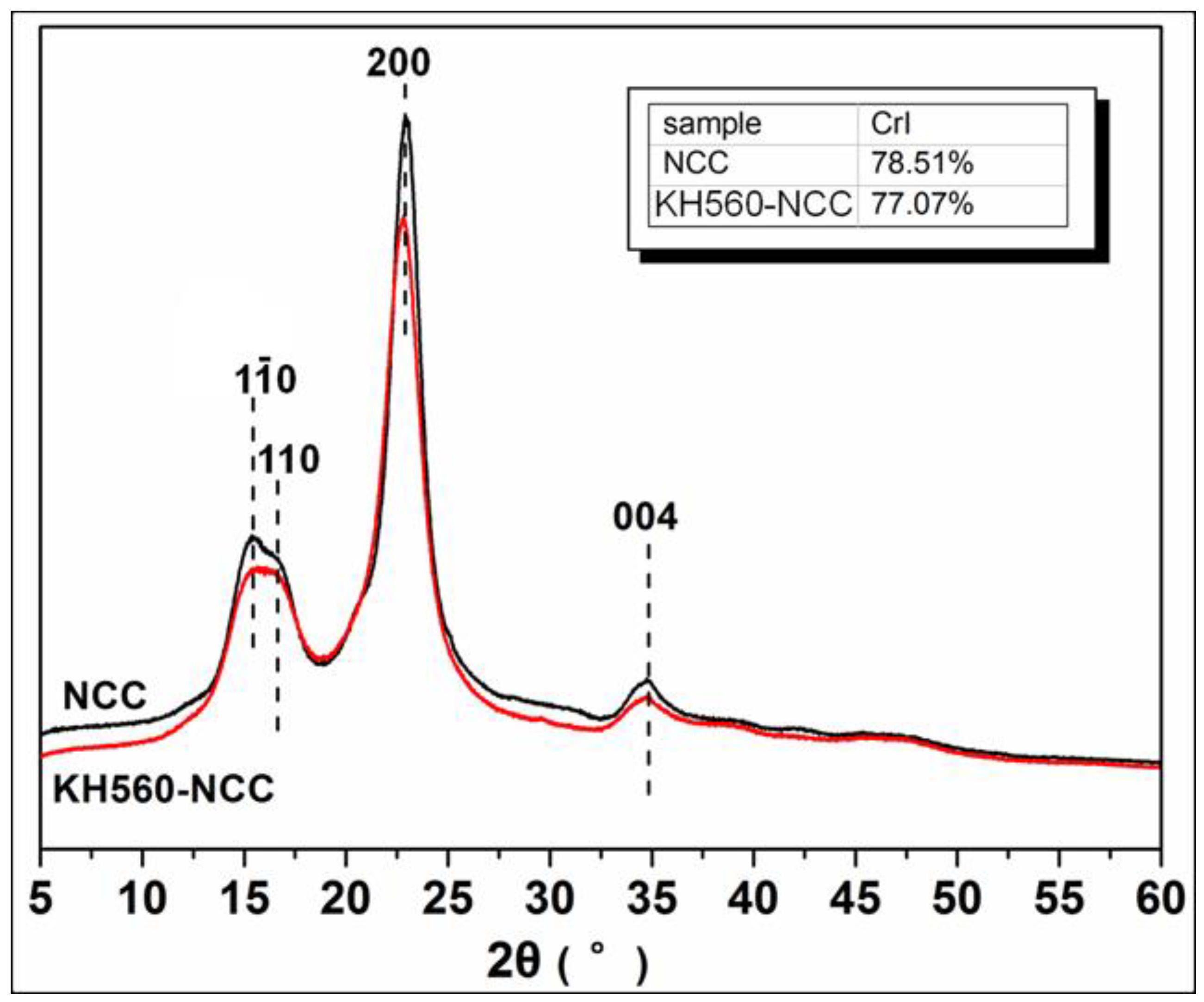
3.3. XRD Analysis
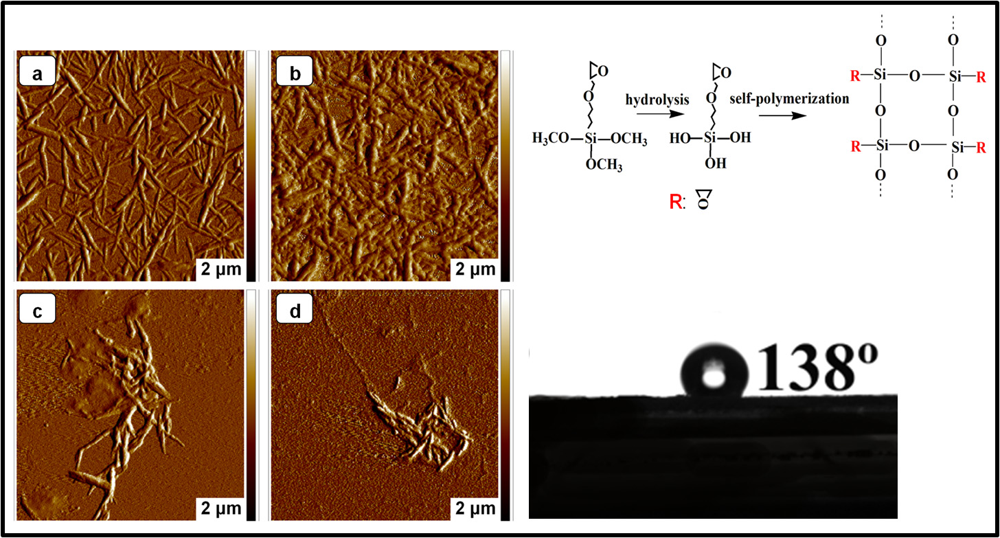
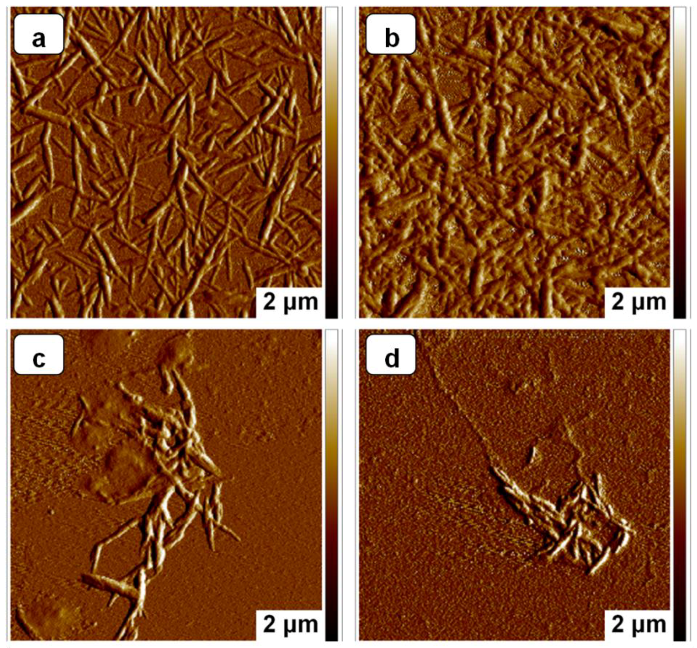
3.4. AFM Analysis
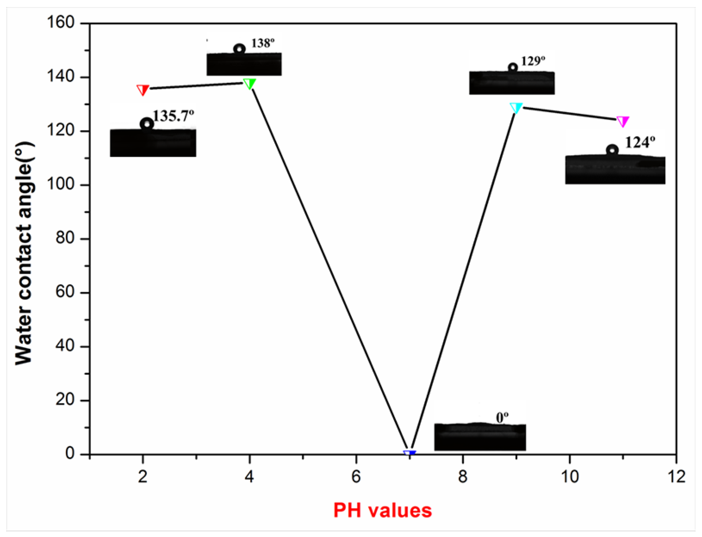
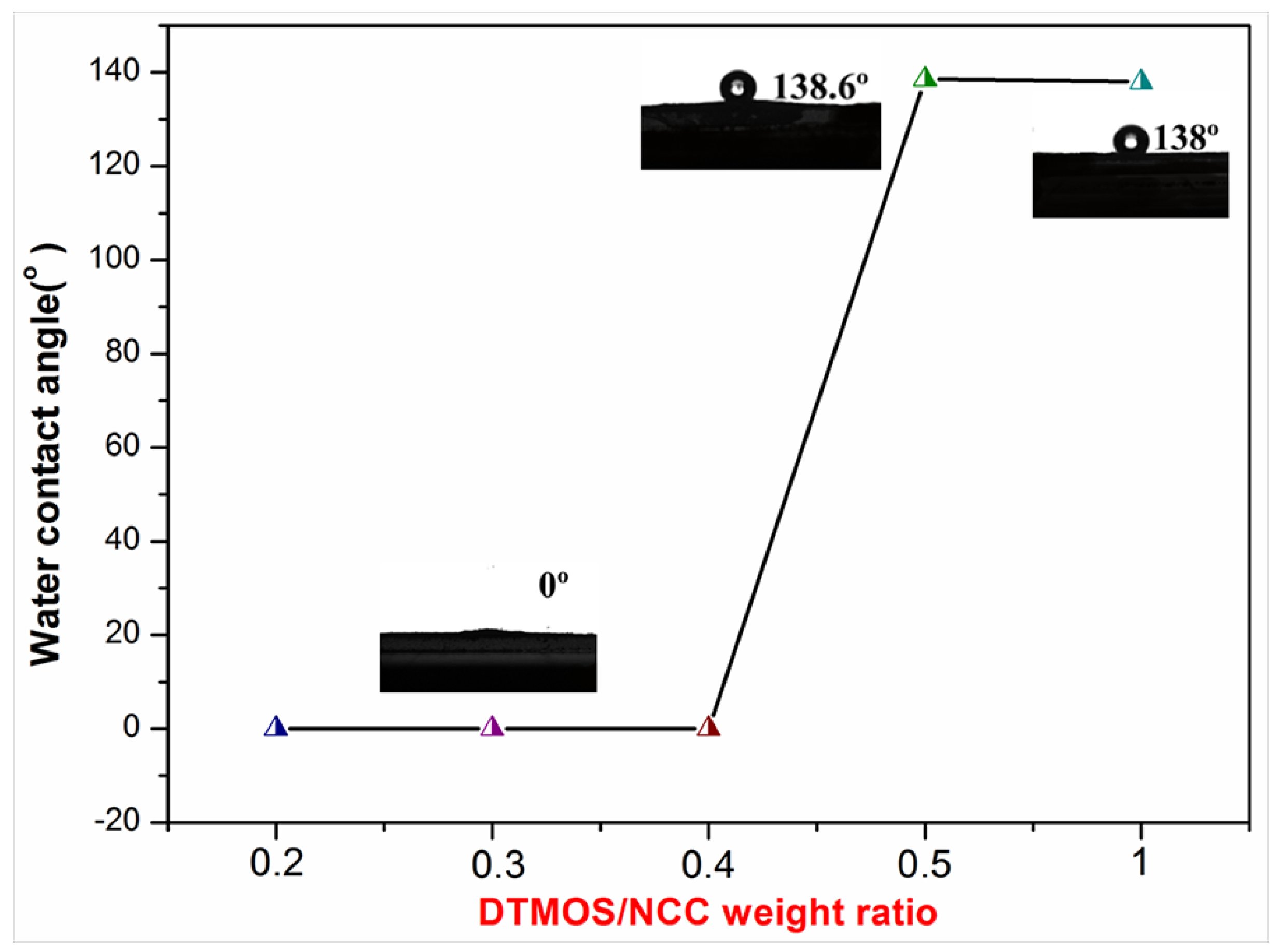
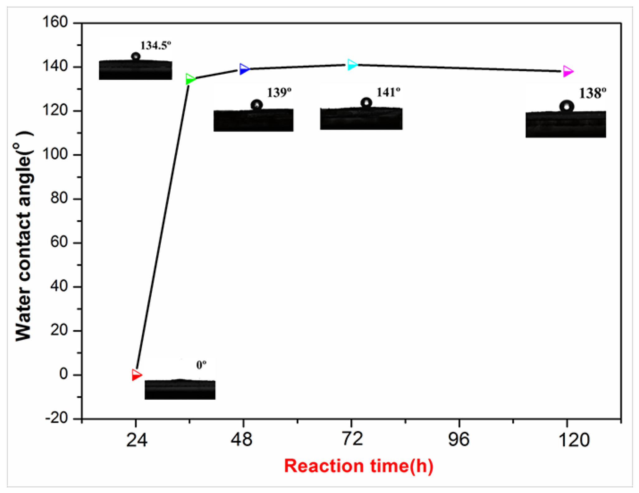
3.5. Hydrophobicity
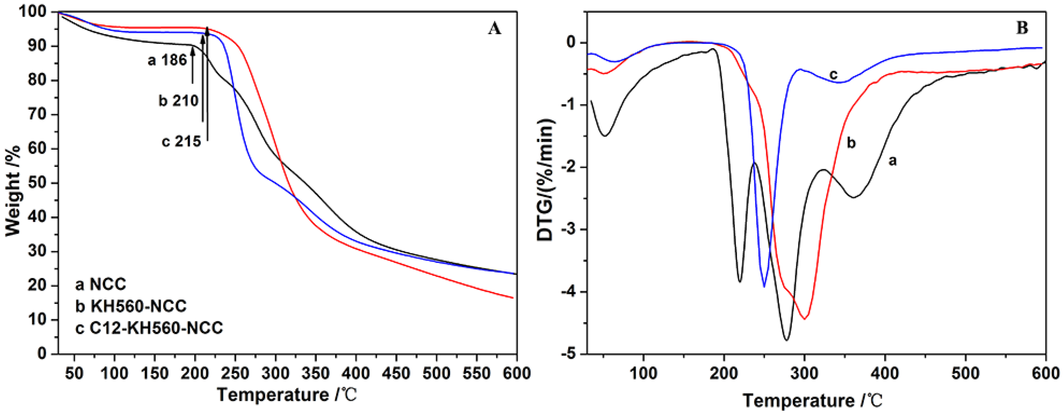
3.6. Thermal Analysis
4. Conclusions
Author Contributions
Funding
Conflicts of Interest
References
- Dufresne, A. Nanocellulose: A new ageless bionanomaterial. Mater. Today 2013, 16, 220–227. [Google Scholar] [CrossRef]
- Lee, S.-Y.; Mohan, D.J.; Kang, I.-A.; Doh, G.-H.; Lee, S.; Han, S.O. Nanocellulose reinforced PVA composite films: Effects of acid treatment and filler loading. Fibers Polym. 2009, 10, 77–82. [Google Scholar] [CrossRef]
- Shang, W.; Huang, J.; Luo, H.; Chang, P.R.; Feng, J.; Xie, G. Hydrophobic modification of cellulose nanocrystal via covalently grafting of castor oil. Cellulose 2013, 20, 179–190. [Google Scholar] [CrossRef]
- Lee, K.-Y.; Quero, F.; Blaker, J.J.; Hill, C.A.S.; Eichhorn, S.J.; Bismarck, A. Surface only modification of bacterial cellulose nanofibres with organic acids. Cellulose 2011, 18, 595–605. [Google Scholar] [CrossRef]
- Lam, E.; Male, K.B.; Chong, J.H.; Leung, A.C.W.; Luong, J.H.T. Applications of functionalized and nanoparticle-modified nanocrystalline cellulose. Trends Biotechnol. 2012, 30, 283–290. [Google Scholar] [CrossRef] [PubMed]
- Lin, N.; Huang, J.; Dufresne, A. Preparation, properties and applications of polysaccharide nanocrystals in advanced functional nanomaterials: A review. Nanoscale 2012, 4, 3274–3294. [Google Scholar] [CrossRef] [PubMed]
- Siqueira, G.; Bras, J.; Dufresne, A. New Process of Chemical Grafting of Cellulose Nanoparticles with a Long Chain Isocyanate. Langmuir 2010, 26, 402–411. [Google Scholar] [CrossRef] [PubMed]
- Lin, N.; Dufresne, A. Surface chemistry, morphological analysis and properties of cellulose nanocrystals with gradiented sulfation degrees. Nanoscale 2014, 6, 5384–5393. [Google Scholar] [CrossRef] [PubMed]
- Goussé, C.; Chanzy, H.; Excoffier, G.; Soubeyrand, L.; Fleury, E. Stable suspensions of partially silylated cellulose whiskers dispersed in organic solvent. Polymer 2002, 43, 2645–2651. [Google Scholar] [CrossRef]
- Frone, A.N.; Berlioz, S.; Chailan, J.-F.; Panaitescu, D.M.; Donescu, D. Cellulose fiber-reinforced polylactic acid. Polym. Compos. 2011, 32, 976–985. [Google Scholar] [CrossRef]
- De Oliveira Taipina, M.; Ferrarezi, M.M.F.; Yoshida, I.V.P.; do Carmo Gonçalves, M. Surface modification of cotton nanocrystals with a silane agent. Cellulose 2013, 20, 217–226. [Google Scholar] [CrossRef]
- Isogai, A.; Saito, T.; Fukuzumi, H. TEMPO-oxidized cellulose nanofibers. Nanoscale 2011, 3, 71–85. [Google Scholar] [CrossRef] [PubMed]
- Inamochi, T.; Funahashi, R.; Nakamura, Y.; Saito, T.; Isogai, A. Effect of coexisting salt on TEMPO-mediated oxidation of wood cellulose for preparation of nanocellulose. Cellulose 2017, 24, 4097–4101. [Google Scholar] [CrossRef]
- Huang, F.; Wu, X.; Yu, Y.; Lu, Y.; Chen, Q. Acylation of cellulose nanocrystals with acids/trifluoroacetic anhydride and properties of films from esters of CNCs. Carbohydr. Polym. 2017, 155, 525–534. [Google Scholar] [CrossRef] [PubMed]
- de Menezes, A.J.; Siqueira, G.; Curvelo, A.A.S.; Dufresne, A. Extrusion and characterization of functionalized cellulose whiskers reinforced polyethylene nanocomposites. Polymer 2009, 50, 4552–4563. [Google Scholar] [CrossRef]
- Andresen, M.; Johansson, L.-S.; Tanem, B.S.; Stenius, P. Properties and characterization of hydrophobized microfibrillated cellulose. Cellulose 2006, 13, 665–677. [Google Scholar] [CrossRef]
- Robles, E.; Csóka, L.; Labidi, J. Effect of Reaction Conditions on the Surface Modification of Cellulose Nanofibrils with Aminopropyl Triethoxysilane. Coatings 2018, 8, 139. [Google Scholar] [CrossRef]
- Paquet, O. Modification de la Surface de la Cellulose par les Organosilanes. Ph.D. Thesis, Université de Grenoble, Grenoble, France, 2012. [Google Scholar]
- Berlioz, S.; Molina-Boisseau, S.; Nishiyama, Y.; Heux, L. Gas-Phase Surface Esterification of Cellulose Microfibrils and Whiskers. Biomacromolecules 2009, 10, 2144–2151. [Google Scholar] [CrossRef] [PubMed]
- Jong, L.; Morelius, E.; Zhang, J.; Wolcott, M.; Holbery, J. Study of the Poly(3-hydroxybutyrate-co-3-hydroxyvalerate)/Cellulose Nanowhisker Composites Prepared by Solution Casting and Melt Processing. J. Compos. Mater. 2008, 42, 2629–2645. [Google Scholar] [CrossRef]
- Tang, L.; Huang, B.; Ou, W.; Chen, X.; Chen, Y. Manufacture of cellulose nanocrystals by cation exchange resin-catalyzed hydrolysis of cellulose. Bioresour. Technol. 2011, 102, 10973–10977. [Google Scholar] [CrossRef] [PubMed]
- Shen, C.; Guo, Z.; Chen, C.; Gao, S. Preparation of inorganic-organic hybrid proton exchange membrane with chemically bound hydroxyethane diphosphonic acid. J. Appl. Polym. Sci. 2012, 126, 954–959. [Google Scholar] [CrossRef]
- Chen, L.; Zhang, C.; Du, Z.; Li, H.; Zhang, L.; Zou, W. Synthesis of poly (n-butyl methacrylate)-(glycidyl methacrylate) block copolymer and its compatibilization at the interface of the QD/epoxy nanocomposite for white LED encapsulation. RSC Adv. 2015, 5, 65184–65191. [Google Scholar] [CrossRef]
- Alemdar, A.; Sain, M. Isolation and characterization of nanofibers from agricultural residues—Wheat straw and soy hulls. Bioresour. Technol. 2008, 99, 1664–1671. [Google Scholar] [CrossRef] [PubMed]
- Oh, S.Y.; Yoo, D.I.; Shin, Y.; Kim, H.C.; Kim, H.Y.; Chung, Y.S.; Park, W.H.; Youk, J.H. Crystalline structure analysis of cellulose treated with sodium hydroxide and carbon dioxide by means of X-ray diffraction and FTIR spectroscopy. Carbohydr. Res. 2005, 340, 2376–2391. [Google Scholar] [CrossRef] [PubMed]
- Lu, Q.; Tang, L.; Lin, F.; Wang, S.; Chen, Y.; Chen, X.; Huang, B. Preparation and characterization of cellulose nanocrystals via ultrasonication-assisted FeCl3-catalyzed hydrolysis. Cellulose 2014, 21, 3497–3506. [Google Scholar] [CrossRef]
- Valadez-Gonzalez, A.; Cervantes-Uc, J.M.; Olayo, R.; Herrera-Franco, P.J. Chemical modification of heneque´n fibers with an organosilane coupling agent. Coposites Part B 1999, 30, 321–331. [Google Scholar] [CrossRef]
- Zhang, C.; Yu, J.; Xu, X.; Sun, Y. Effect of surface organic modified layered double hydroxide on UV ageing resistance of bitumen. Pet. Sci. Technol. 2017, 35, 488–494. [Google Scholar] [CrossRef]
- Bendahou, A.; Hajlane, A.; Dufresne, A.; Boufi, S.; Kmddami, H. Esterification and amidation for grafting long aliphatic chains on to cellulose nanocrystals: A comparative study. Res. Chem. Intermed. 2014, 41, 4293–4310. [Google Scholar] [CrossRef]
- Xhanari, K.; Syverud, K.; Stenius, P. Emulsions stabilized by microfibrillated cellulose: The effect of hydrophobization, concentration and O/W ratio. J. Dispers. Sci. Technol. 2011, 32, 447–452. [Google Scholar] [CrossRef]


| Sample | Elemental Analyses (%) | Binding Energy (eV) | ||||
|---|---|---|---|---|---|---|
| C | O | Si | C1, 285 ± 0.1 C–C/C–H (%) | C2, 286.4 ± 0.1 C–O (%) | C3, 287.7 ± 0.1 O–C–C/C=O (%) | |
| NCC | 59.87 | 40.12 | 0 | 26.4 | 59.7 | 13.9 |
| KH560-NCC | 55.58 | 38.18 | 6.25 | 21.11 | 65.61 | 13.28 |
| Sample | Sample Detail | VNaOH (mL) |
|---|---|---|
| blank 1 | acetone and HCl | 7.2 |
| blank 2 | acetone, HCl and 0.5053 g of NCC | 7.2 |
| sample 1 | acetone, HCl and 0.5024 g of KH560-NCC | 7.5 |
| Sample | Tonset/°C | Tmax/°C |
|---|---|---|
| NCC | 186 | 278 |
| KH560-NCC | 210 | 300 |
| C12-KH560-NCC | 215 | 250 |
© 2018 by the authors. Licensee MDPI, Basel, Switzerland. This article is an open access article distributed under the terms and conditions of the Creative Commons Attribution (CC BY) license (http://creativecommons.org/licenses/by/4.0/).
Share and Cite
Lin, W.; Hu, X.; You, X.; Sun, Y.; Wen, Y.; Yang, W.; Zhang, X.; Li, Y.; Chen, H. Hydrophobic Modification of Nanocellulose via a Two-Step Silanation Method. Polymers 2018, 10, 1035. https://doi.org/10.3390/polym10091035
Lin W, Hu X, You X, Sun Y, Wen Y, Yang W, Zhang X, Li Y, Chen H. Hydrophobic Modification of Nanocellulose via a Two-Step Silanation Method. Polymers. 2018; 10(9):1035. https://doi.org/10.3390/polym10091035
Chicago/Turabian StyleLin, Wensheng, Xiaoyong Hu, Xueqing You, Yingying Sun, Yueqin Wen, Wenbin Yang, Xinxiang Zhang, Yan Li, and Hanxian Chen. 2018. "Hydrophobic Modification of Nanocellulose via a Two-Step Silanation Method" Polymers 10, no. 9: 1035. https://doi.org/10.3390/polym10091035
APA StyleLin, W., Hu, X., You, X., Sun, Y., Wen, Y., Yang, W., Zhang, X., Li, Y., & Chen, H. (2018). Hydrophobic Modification of Nanocellulose via a Two-Step Silanation Method. Polymers, 10(9), 1035. https://doi.org/10.3390/polym10091035