Abstract
Composite-to-metal interference-fit is widely used in the aerospace field, where the problem of the damage and failure of composite materials is particularly critical. A numerical study was conducted on the damage and failure of carbon fiber composite sleeves with multiple structural parameters during interference-fit assembly. ABAQUS/Explicit simulation of interference-fit was performed with the three-dimensional finite element method, and the VUMAT subroutine with three-dimensional Hashin damage was utilized to investigate the initiation and evolution of composite component damage. The effects of different relative wall thicknesses and layup sequences on the selection of maximum interference were analyzed. The results reveal that the stress distribution on the inner surface of the sleeve is more uniform with the condition of radial layup. Radial layup enables 0.2% interference at 25% wall thickness, a 100% increase over axial layup. This study contributes to addressing long-standing issues in the aerospace field, such as connection failure and insufficient fatigue life. It is of great significance for improving structural performance, reducing costs, and promoting technological innovation.
1. Introduction
Hybrid composite materials played a critical role in aerospace, automotive, and biomedical applications [1]. Specifically, T800/924C carbon fiber composites and TC4 titanium alloy were extensively employed in aerospace structures due to their superior mechanical performance [2]. Compared to alternatives such as glass fiber composites, carbon fiber composites offered a significantly higher modulus, enabling them to endure complex loading conditions typical in aerospace environments [3]. Furthermore, TC4 titanium alloy, characterized by its high strength-to-weight ratio, effectively reduced plastic deformation of metallic shafts during interference-fit assembly, thereby ensuring precise control of the interference. In aircraft structures, interference-fit connection technology of composite was adopted widely due to its advantages of high load-bearing capacity [4,5]. An appropriate interference-fit could effectively adjust load distribution and reduce the stress concentration to a certain extent by increasing the contact area between shaft and sleeve, decreasing the stress amplitude under alternating loads, delaying fatigue failure, and enhancing load capacity and fatigue life [6,7,8,9,10,11,12]. However, composite materials were brittle and highly sensitive to assembly gaps. Selecting a proper interference could significantly enhance the connection strength of composite structures, thereby improving the service life of the aircraft [13,14].
Binner Goren Kiral found that the fit pattern did not affect the failure mode, and that interference-fit improved the compressive strength of composite pin joints [15]. Wang et al. proposed that the hole–axis interference significantly influenced the fatigue life of CFRP/Al-alloy bolted joints. Initially, the fatigue life increased with an increase in hole–axis interference, but subsequently, began to decline [16]. However, in the process of forming an interference-fit assembly, the hole edge material was subjected to higher residual compressive stress, which was more susceptible to damage under external loads. Current research on interference-fit has been conducted under the assumption of proper structural installation, focusing on the effect of interference, but lacks investigation into damage mechanisms during the fitting process [17,18]. In addition to the traditional hard squeeze interference-fit connection method, Raju et al. found that the bush bolt could effectively improve the load-carrying capacity of the hybrid joint structure [19]. Domestic researchers made a brief introduction to the structure, but the lack of systematic research on the installation mechanism, and the lack of an effective basis for the selection of reliable interference in the installation process, limited the structure to applications [20,21]. Cheng et al. conducted research on the tensile properties of composite–metal joints with bush countersunk bolts, and found that the interference between the bolt and the bush was an important factor affecting the strength of the joint [22]. The moderate increase in the amount of interference improved both the stiffness and strength of the joint. It was of great engineering significance to reasonably design the amount of interference to improve the tensile properties of the joint, but the factors of damage caused by installation were not considered in the simulation process, and no clear recommendations were made for the amount of interference. Kang et al. investigated the damage of composite laminates fabricated using prepregs of different thicknesses in interference-fit, finding that ultra-thin laminates can effectively reduce damage to the hole walls during the installation of interference-fit. Compared to thick laminate, hybrid laminate and ultra-thin laminate have significantly less damage at the exit, such as matrix cracking, delamination and burr formation, and ultra-thin laminate have more significant effects [23]. Wang et al. conducted a detailed experimental study of the strength of single-lap composite joints at different layer thicknesses and interference sizes, finding that the installation force of thin-layer joints with the same interference size was less than that of thick-layer joints, and thick-layer joints showed the optimum bearing strength at 1.00% interference [24]. However, the effect of the wall thickness of the hole and the layup sequences of the composite on the damage of the composite structure and the choice of the amount of interference is not investigated.
This article simulated the interference-fit between the TC4 shaft and the composite sleeve based on a three-dimensional Hashin failure model of composite materials. Taking into account the influence of component size and composite layup sequence on interference-fit, this paper explored the mechanism of how different structural parameters affected interference-fit and the range of reliable interference selection. The work provided a basis for setting the interference in an actual composite-to-metal interference-fit.
2. Simulation Basis
2.1. Material Parameters
The sleeve material is T800/924C carbon fiber composite material, and the shaft material is TC4 titanium alloy. Table 1 presents the properties of T800/924C carbon fiber composite and the properties of TC4 titanium alloy are shown in Table 2.
Table 1.
Material parameters of T800/924C [25].
Table 2.
Material parameters of TC4 titanium alloy [26].
2.2. Damage Initiation Criteria
Damage initiation criteria refer to the standards for determining the stress state under which a material begins to experience damage or degradation. For composite materials, due to their complex microstructure and mechanical properties, damage initiation criteria typically need to consider multiple stress states and failure modes. There are five commonly used damage initiation criteria: the Puch criterion, the Chang–Chang criterion, the Hoffman failure criterion, the Tsai–Wu failure criterion, and the Hashin failure criterion [27,28,29,30,31,32,33].
During high-speed impact, composite material layers can experience various failure modes, including matrix tensile failure, matrix compressive failure, fiber tensile failure, and others. To more accurately simulate the failure behavior of composite material layers, this study employs the three-dimensional Hashin damage initiation criterion based on strain [34], which includes six failure forms: fiber tension, fiber compression, matrix tension, matrix compression, in-plane shear, and out-of-plane shear, with the following expressions:
Fiber stretching ():
Fiber compression ():
Matrix stretching ():
Matrix compression ():
In-plane shear (1–2 plane):
Exterior shear (1–3 and 2–3 plane):
Among these, 1, 2, and 3 represent the fiber direction (X), the in-plane perpendicular direction (Y), and the out-of-plane perpendicular direction (Z), respectively. and are the tensile and compressive failure strains in the fiber direction, while and are the tensile and compressive failure strains in the matrix direction. (i, j = 1, 2, 3, i ≠ j) represents the shear failure strain. Composite materials can simultaneously exhibit multiple damage modes. When any damage parameter (, , , , , ) reaches 1, the corresponding damage initiation criterion is satisfied for the element, followed by stiffness degradation.
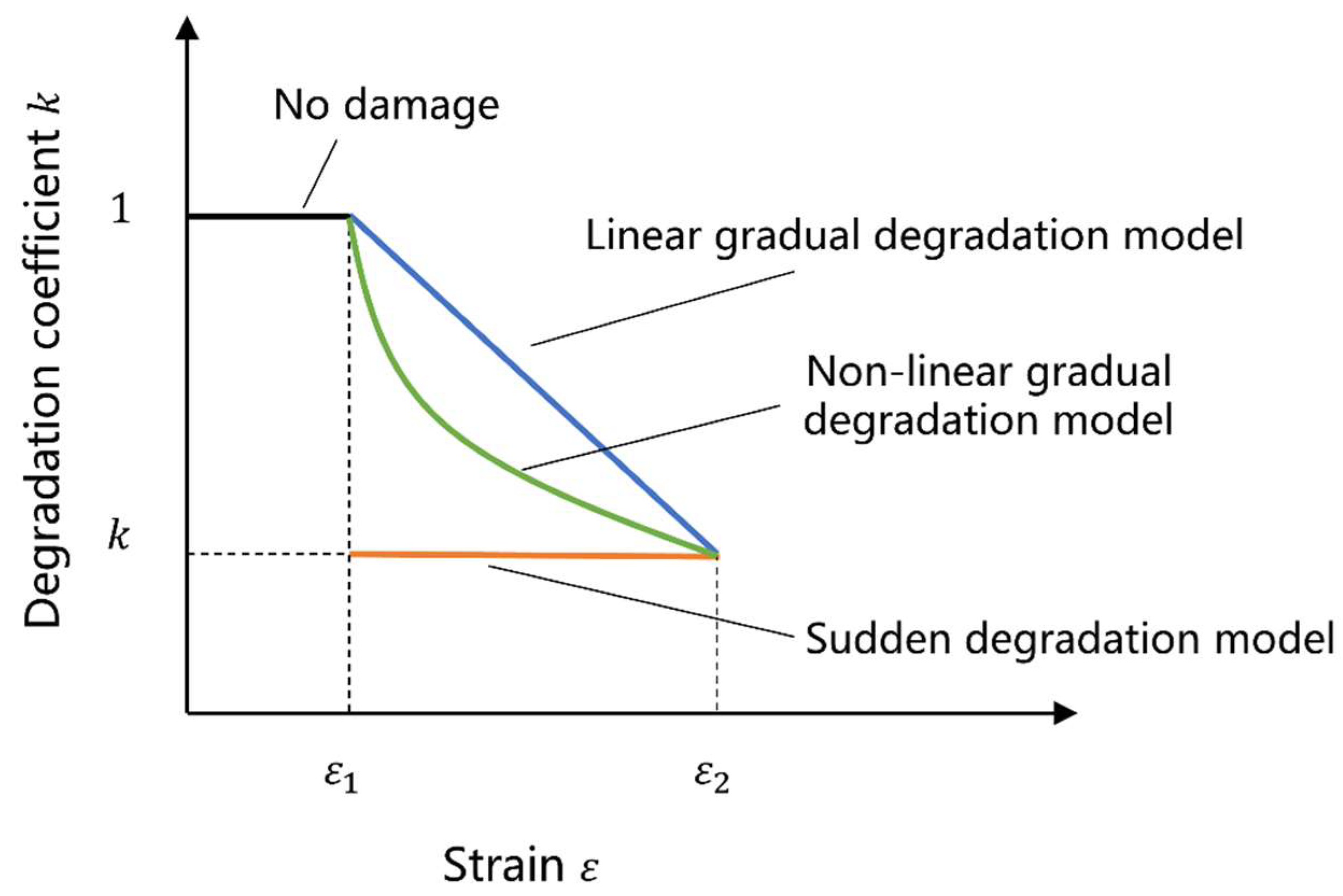
2.3. Damage Evolution Model
Damage evolution describes the rate of material stiffness degradation after reaching the corresponding damage initiation criteria. When the material satisfies the damage initiation criterion, the element is deemed to begin damage, losing its load-bearing capacity and experiencing stiffness degradation [35]. Figure 1 shows three degradation models for the mechanical properties of composite materials. The sudden degradation model represents that when composite materials reach a certain stress or strain threshold, their mechanical properties suddenly degrade; the linear gradual degradation model indicates that as stress or strain increases, the material’s load-bearing capacity decreases linearly, with a constant rate of performance degradation; the nonlinear gradual degradation model indicates that as stress or strain increases, the rate of capacity decrease gradually increases.
Figure 1.
Three types of degradation.
The definition of damage evolution consists of two components. The first component involves the effective displacement at complete failure relative to the effective displacement at the onset of damage or the energy dissipated due to failure (also referred to as fracture energy). The second component of the damage evolution definition specifies the nature of the evolution of the damage variable between the onset of damage and final failure. This can be achieved by defining linear or exponential softening laws or directly specifying as a tabular function of the effective displacement relative to the effective displacement at the onset of damage.
This paper considers the brittleness of carbon fiber reinforced composites, where the degradation of stiffness in composites macroscopically manifests as a reduction in the material’s elastic modulus, with the reduction scheme shown in Table 3. If a composite unit experiences matrix failure, fiber failure, or shear failure, the unit is then deleted.
Table 3.
Stiffness degradation scheme.
3. Modeling and Simulation
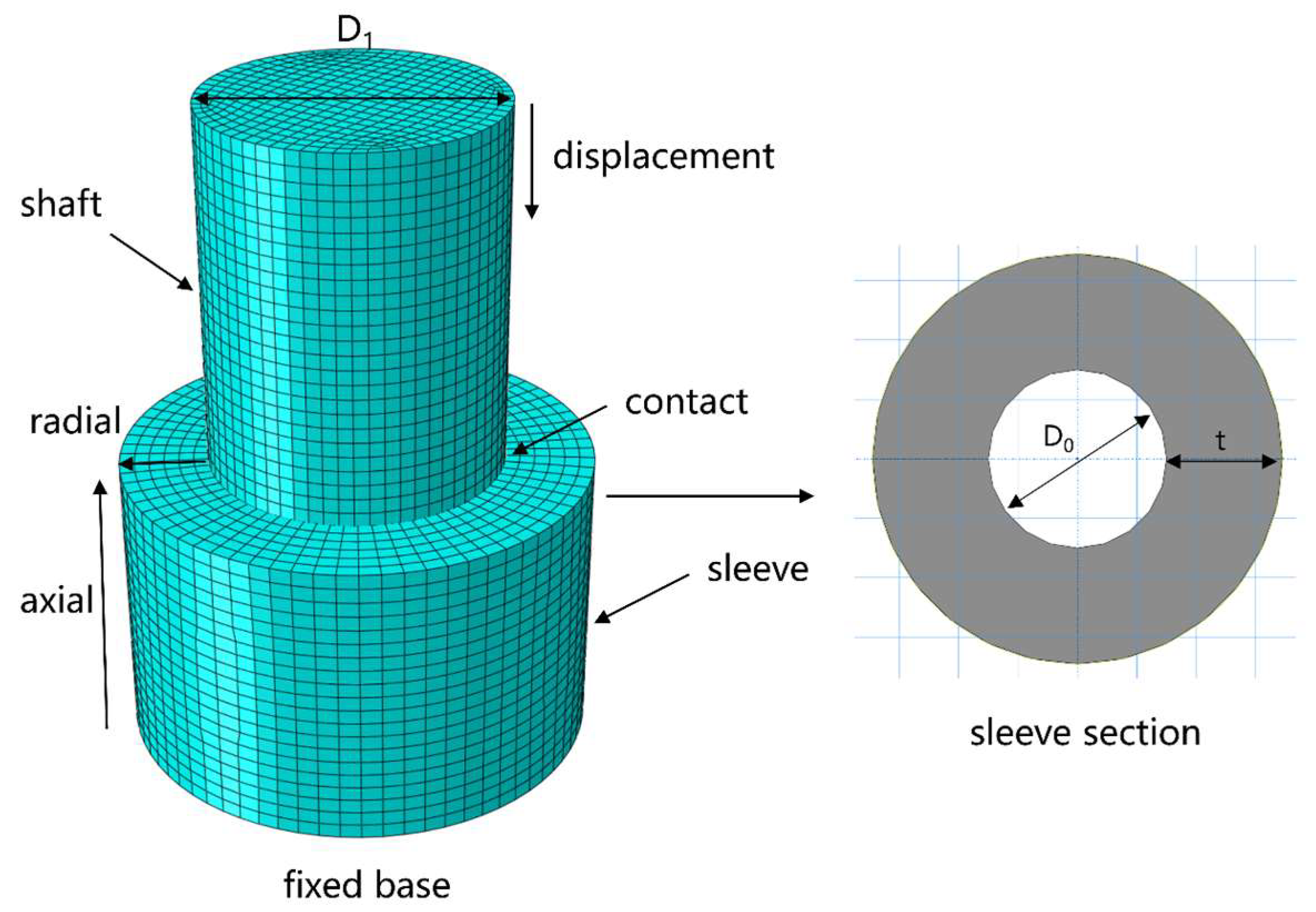
3.1. Interference-Fit Numerical Model
A three-dimensional finite element model of the interference-fit between the T800/924C composite material shaft and the TC4 titanium alloy shaft is established, as shown in Figure 2. The shaft height is 25 mm, the sleeve height is 20 mm, the inner diameter of the sleeve is 20 mm, and the sleeve has two layup sequences: axial and radial. The interference is altered by changing the shaft diameter. To effectively simulate the progressive damage process, the ABAQUS 2022 finite element analysis software is used to model the problem using explicit dynamics, employing the three-dimensional deformable solid C3D8R. Considering both computational time and result accuracy, the element size is selected as 1 mm.
Figure 2.
Three-dimensional finite element model of interference-fit between T800/924C composite shaft and TC4 titanium alloy shaft.
Interference is defined as follows:
In the formula presented, indicates the diameter of the shaft.
Relative wall thickness is defined as follows:
In the formula presented, indicates the wall thickness of the sleeve.
Figure 2 gives the boundary conditions for the finite element model. The contact type between the TC4 shaft body and the inner surface of the composite material sleeve is set as friction contact, the outer surface of the pin sleeve shaft is set as contact surface, the inner surface of the base cylinder is set as target surface, and the friction coefficient f is 0.3 [36,37]. The interference is achieved by controlling the contact offset. The damage mechanical behavior of composites is simulated by using the Hashin failure criterion and the progressive damage model. During the numerical calculation, the VUMAT sub-program is called to evaluate the onset and evolution of damage in the simulation model.
3.2. Simulation of Interference-Fit with Different Relative Wall Thicknesses and Layup Sequences of the Sleeve
Based on the aforementioned modeling to study the effect of different wall thicknesses on the interference. Considering that different sleeve wall thicknesses directly affect the interference, and due to weight restrictions, the relative wall thickness δ of the sleeve generally does not exceed 25%. Therefore, δ is taken as 5%, 10%, 15%, 20%, and 25% to simulate the damage conditions of the sleeve under interference of 0.1%, 0.2%, and 0.3%.
In addition to the relative wall thickness of the composite sleeve, the layup sequences of the composite prepreg during sleeve fabrication also impact the interference. Two different layup sequences, axial and radial, were set up and simulations were conducted separately for each.
3.3. Validation of Structural Parameters in Composite Structure Design
To ensure the accuracy of the influence patterns of the structural parameters derived from simulations, the sleeve was reconfigured with an inner diameter D0 of 40 mm and subjected to the same simulations as described above.
4. Results and Discussion
This section examines the damage conditions of composite sleeves under various structural parameters during interference-fit. Through the analysis of damage patterns, this study summarizes the selection rules for interference under different structural parameters and validates the model.
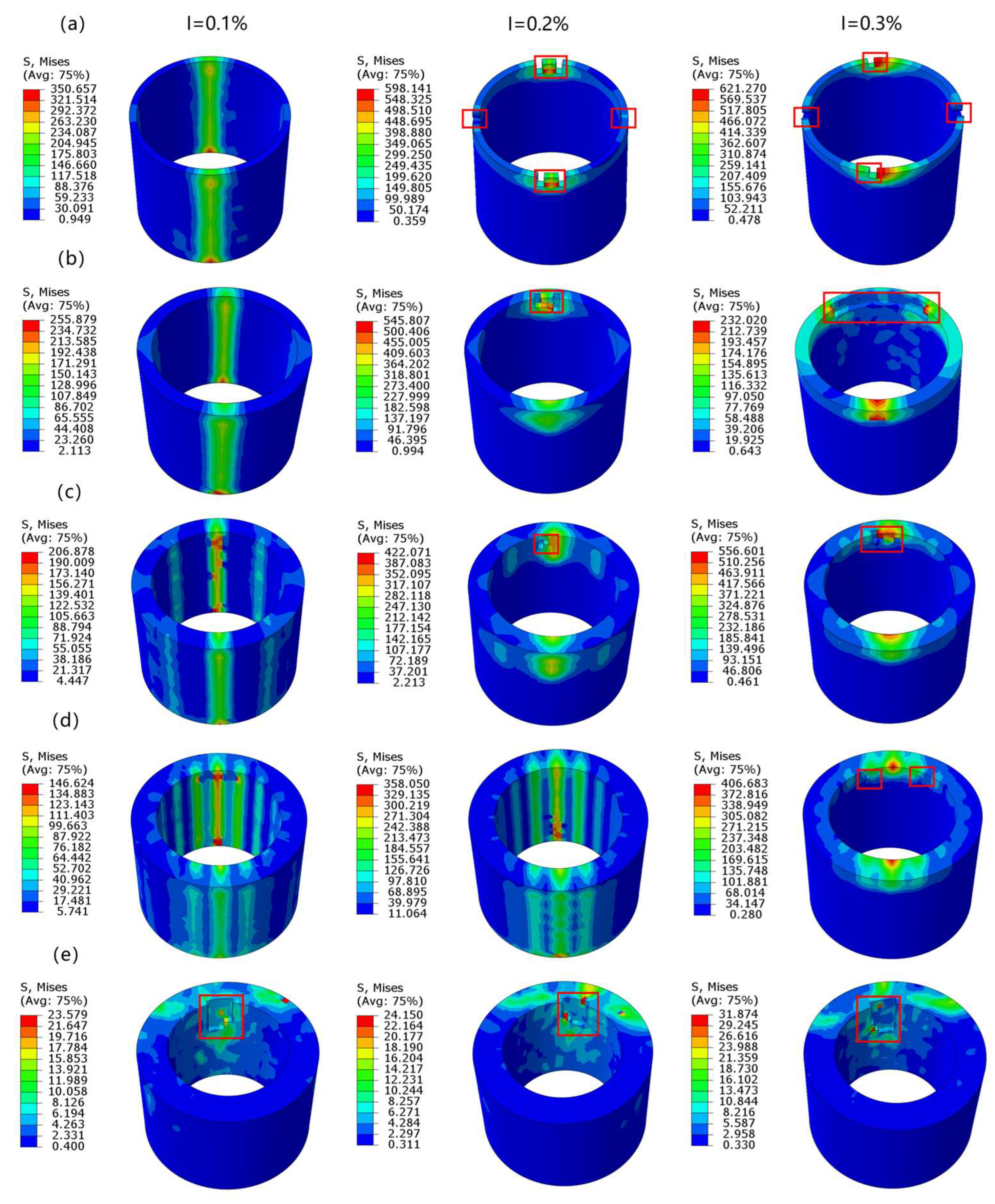
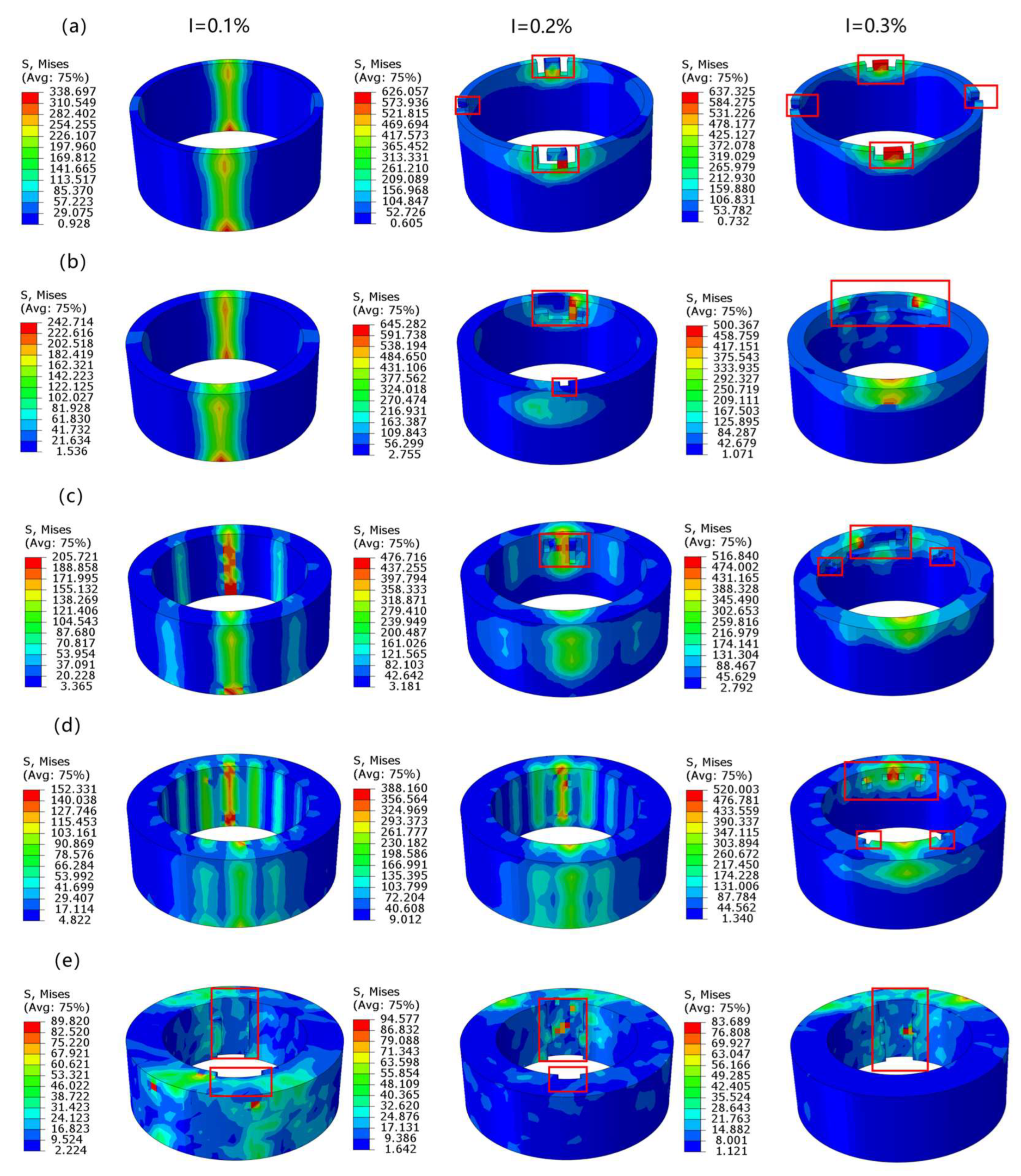
4.1. Simulation Results Under Axial Layup
When the relative wall thickness is 5%, 10%, 15%, 20%, and 25%, respectively, the damage conditions of the composite sleeve in the shaft-sleeve interference-fit model under 0.1%, 0.2%, and 0.3% interference are shown in Figure 3. The red frame in the figure indicates the area of the injury. As shown in the figure, when the relative wall thickness is 5%, 10%, and 15%, the sleeve can only complete the interference-fit at an interference of 0.1%, which is due to the excessively low strength of the sleeve caused by the small wall thickness. When the relative wall thickness is 20%, the sleeve can further complete the interference-fit at an interference of 0.2%. However, when the relative wall thickness is 25%, the sleeve fails in all three interference conditions. This is because, under the axial layup sequence, the stress direction on the inner surface of the sleeve during interference-fit is perpendicular to the direction of the fibers, which has poor ductility. When the sleeve wall thickness is too large, the stress accumulation during the interference-fit process is more likely to cause damage to the inner surface of the sleeve. From the above results, it can be concluded that for composite sleeves with axial layup, both excessively large or small relative wall thicknesses are detrimental to interference-fit, and the maximum range of selectable interference is achieved when the relative wall thickness is 20%.
Figure 3.
Damage conditions of the shaft-sleeve interference-fit model under the axial layup sequence of the sleeve with relative wall thickness δ being (a) 5%, (b) 10%, (c) 15%, (d) 20%, and (e) 25% at interference levels I = 0.1%, I = 0.2%, and I = 0.3%. (Stress unit: MPa).
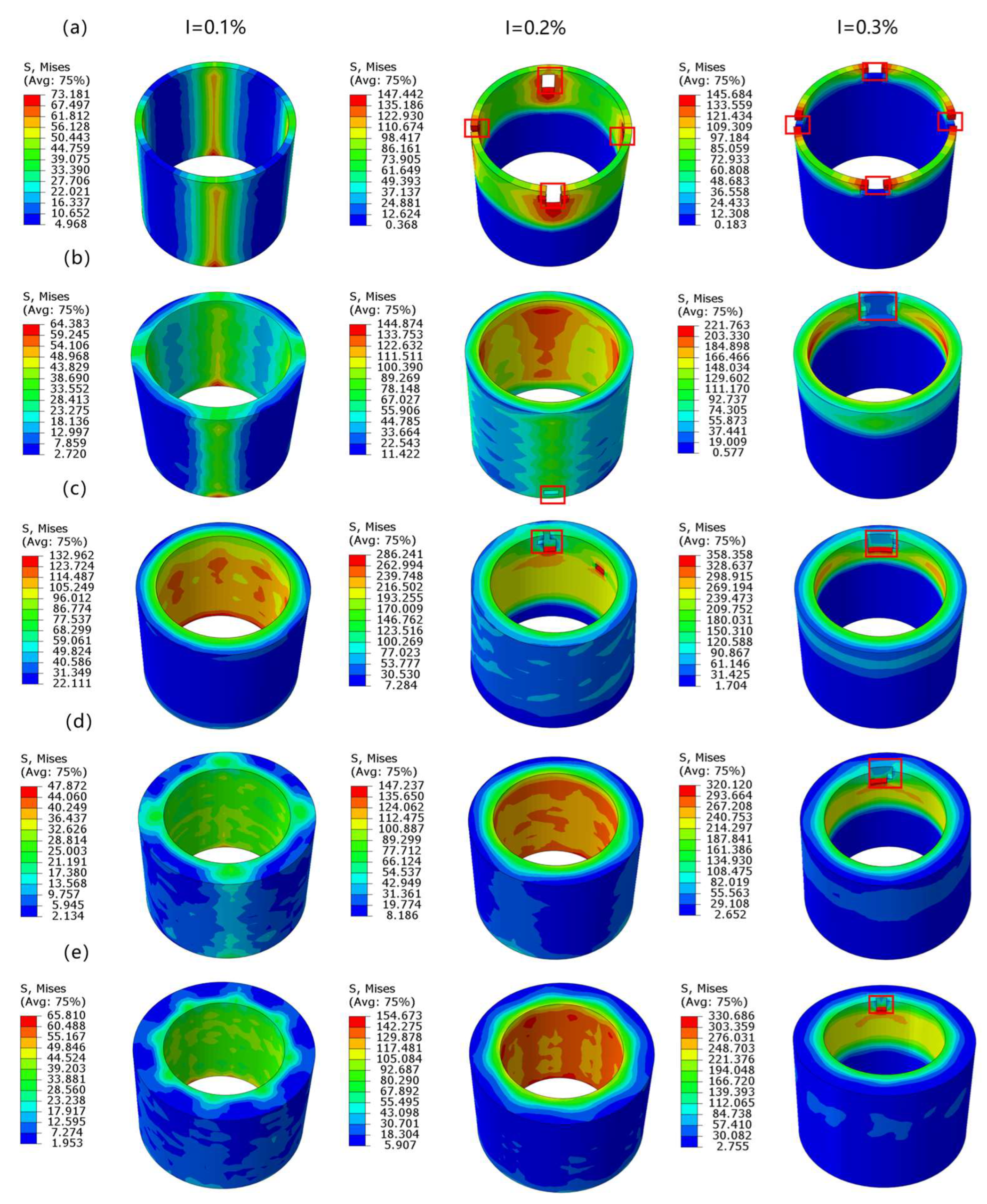
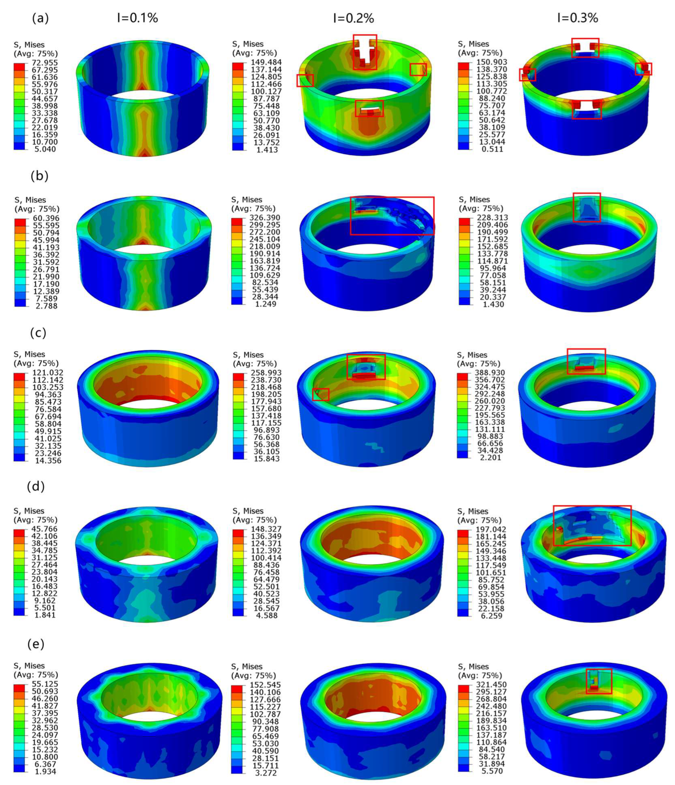
4.2. Simulation Results Under Radial Layup
The damage conditions of the sleeve during interference-fit under radial layup with relative wall thickness δ of 5%, 10%, 15%, 20%, and 25% at interference of 0.1%, 0.2%, and 0.3% are shown in Figure 4. As can be seen from the figure, when the relative wall thickness is 5%, 10%, and 15%, the sleeve can complete the interference-fit at an interference of 0.1% without damage failure. When the relative wall thickness is 20% and 25%, the sleeve can further complete the interference-fit at an interference of 0.2%. This is because, during interference-fit, the primary loading direction of the sleeve is perpendicular to the inner wall of the sleeve and outward. Radial layup allows the fiber direction with the highest strength to bear the load, while axial layup bears the load in the weaker matrix direction. Therefore, while axial layup achieves interference-fit at relative wall thicknesses of 5%, 10%, 15%, and 20%, radial layup further achieves interference-fit at a relative wall thickness of 25%. Combining the results from both layup sequences, it is observed that the interference does not exceed 0.2% in all successful interference-fit experiments. This is due to the material properties of T800/924C limiting the selection of maximum interference. Additionally, comparing the stress contour plots from different layup sequences reveals that the stress distribution on the inner surface of the sleeve during interference-fit differs. Under radial layup, the stress distribution on the inner surface of the sleeve is more uniform.
Figure 4.
Damage conditions of the shaft-sleeve interference-fit model under radial layup of the sleeve with relative wall thickness δ being (a) 5%, (b) 10%, (c) 15%, (d) 20%, and (e) 25% at interference levels I = 0.1%, I = 0.2%, and I = 0.3%. (Stress unit: MPa).
4.3. Verification of Accuracy of Simulation Results
The damage conditions of the shaft-sleeve interference-fit model under axial and radial layup sequences at 0.1%, 0.2%, and 0.3% interference with an inner diameter of 40 mm and relative wall thickness δ of 5%, 10%, 15%, 20%, and 25% are shown in Figure 5 and Figure 6. As seen from Figure 5, when the relative wall thickness is 5%, 10%, and 15%, the sleeve can only complete the interference-fit at 0.1% interference, which is due to the excessively small wall thickness leading to insufficient strength of the sleeve. When the relative wall thickness is 20%, the sleeve can further complete the interference-fit at 0.2% interference. However, when the relative wall thickness is 25%, the sleeve fails in all three interference conditions. As seen in Figure 6, when the relative wall thickness is 5%, 10%, and 15%, the sleeve can complete the interference-fit at 0.1% interference without damage failure. When the relative wall thickness is 20% and 25%, the sleeve can further complete the interference-fit at 0.2% interference.
Figure 5.
Damage conditions of the shaft-sleeve interference-fit model under different relative wall thickness δ (a) 5%, (b) 10%, (c) 15%, (d) 20%, and (e) 25% for the axial layup configuration of the sleeve when D0 = 40 mm, at I = 0.1%, 0.2%, and 0.3%. (Stress unit: MPa).
Figure 6.
Damage conditions of the shaft-sleeve interference-fit model under different relative wall thickness δ (a) 5%, (b) 10%, (c) 15%, (d) 20%, and (e) 25% for the radial layup configuration of the sleeve when D0 = 40 mm, at I = 0.1%, 0.2%, and 0.3%. (Stress unit: MPa).
Figure 7 shows the variation in the maximum interference with relative wall thickness δ under axial and radial layups for two sizes = 20 mm and = 40 mm. It can be seen that, under axial layup, the maximum interference for both sizes reaches 0.1% when the relative wall thickness is 5%, 10%, and 15%; reaches 0.2% when the relative wall thickness is 20%; interference-fit cannot be achieved when the relative wall thickness is 25%. Under radial layup, the maximum interference reaches 0.1% when the relative wall thickness is 5%, 10%, and 15%; and reaches 0.2% when the relative wall thickness is 20% and 25%. These results validate the accuracy of the simulation results, indicating that, under two different layup methods, the maximum interference is uniquely determined once the relative wall thickness δ of the sleeve is fixed, regardless of the specific dimensions of the sleeve.
Figure 7.
Maximum interference I as a function of relative wall thickness δ for (a) axial layup and (b) radial layup when = 20 mm and = 40 mm.
5. Conclusions
Based on the three-dimensional Hashin failure model, the paper simulated the interference-fit between the TC4 titanium alloy shaft and T800/924C composite sleeve with different relative wall thicknesses and layup sequences using 3D finite element analysis. The damage results of the sleeve were analyzed with various structural parameters and the following conclusions were drawn:
- (1)
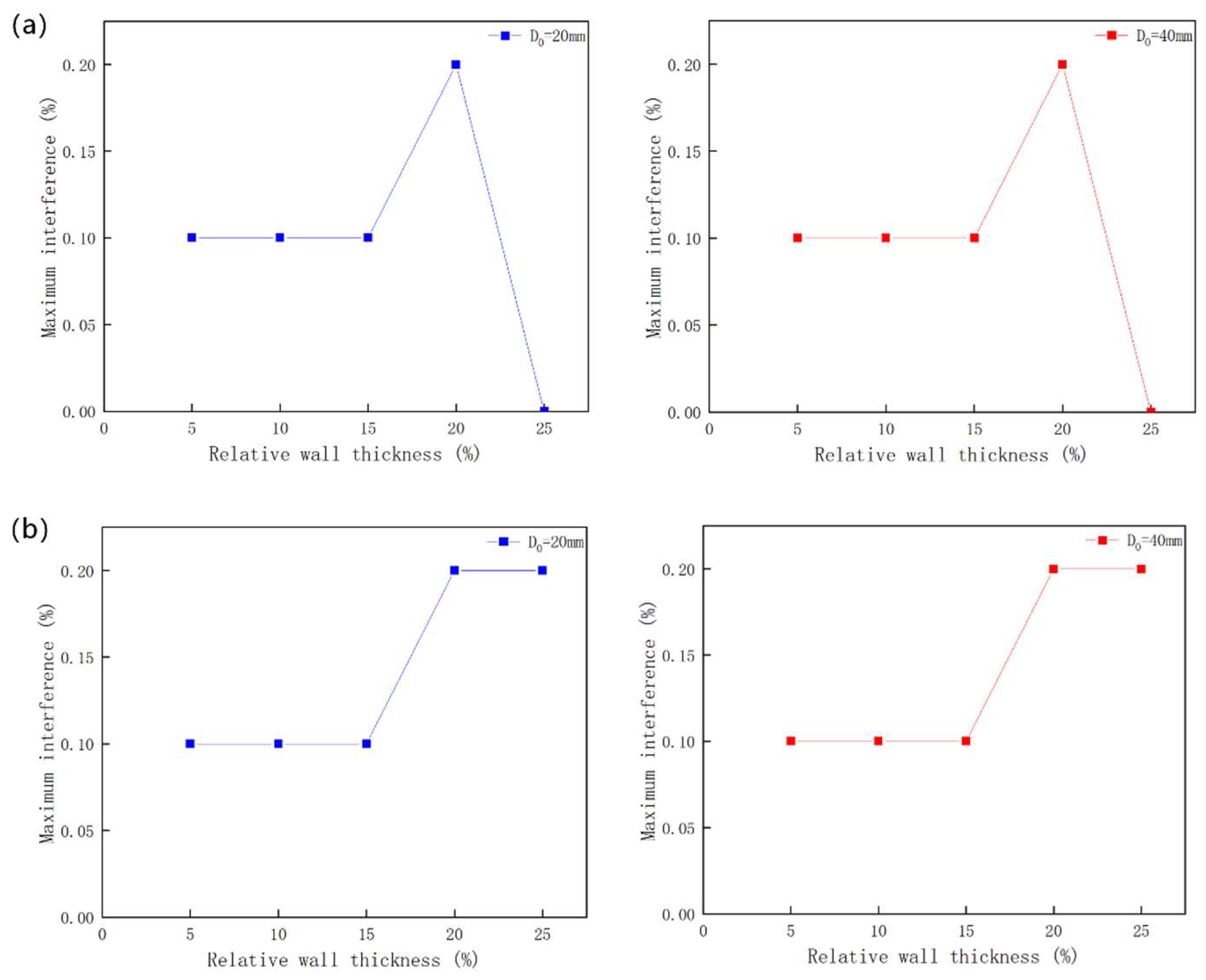
- For the T800/924C carbon fiber composite sleeve under axial layup, the maximum interference is 0.1% at relative wall thicknesses of 5%, 10%, and 15%, reaches 0.2% at a relative wall thickness of 20%, and an interference-fit is not possible when the relative wall thickness is 25%.
- (2)
- With the condition of radial layup, the maximum interference is 0.1% at relative wall thicknesses of 5%, 10%, and 15%, and reaches 0.2% at relative wall thicknesses of 20% and 25%.
- (3)
- With the condition of radial layup, the stress distribution on the inner surface of the sleeve is more uniform. Radial layup effectively avoids local stress concentration compared to axial layup. Radial layup can effectively address the issue of the inability to achieve interference-fit when the relative wall thickness is too large in the axial layup, enabling a maximum interference of 0.2% at a relative wall thickness of 25%.
Author Contributions
Conceptualization, S.J. and X.G.; methodology, S.J., X.G. and D.Z.; formal analysis, S.J. and X.G.; investigation, X.G.; resources, M.W.; data curation, S.J. and X.G.; writing—original draft preparation, S.J., X.G. and D.Z.; writing—review and editing, R.Z.; visualization, X.G.; supervision, R.Z. All authors have read and agreed to the published version of the manuscript.
Funding
This research was funded by the project (grant number 20232BBE50003) from the Key Research and Development Program of Jiangxi Province, the project (grant number 6142909230208) from The National Key Laboratory for Precision Hot Processing of Metals, and the Fundamental Research Funds for the Central Universities (Qingba from BeiHang University). All authors have read and agreed to the published version of the manuscript.
Data Availability Statement
The original contributions presented in this study are included in the article. Further inquiries can be directed to the corresponding author.
Conflicts of Interest
The authors declare no conflict of interest.
References
- Hou, X.; Wang, H.; Geng, W.; Yang, L.; Wang, J. The Effect of the Modified Starch with Side Chain on the Morphology of Copper Particles and the Antibacterial Properties of Starch/Copper Composite Material. Int. J. Biol. Macromol. 2024, 283, 137488. [Google Scholar] [CrossRef] [PubMed]
- Xu, G.; Li, X.; Zhu, Y. Support Stiffness Effects on Damage Behavior of Thin-Walled Composite Interference-Fit Joints in the Installation. Eng. Fail. Anal. 2024, 156, 107841. [Google Scholar] [CrossRef]
- Fazeli, M.; Islam, S.; Baniasadi, H.; Abidnejad, R.; Schlapp-Hackl, I.; Hummel, M.; Lipponen, J. Exploring the Potential of Regenerated Ioncell Fiber Composites: A Sustainable Alternative for High-Strength Applications. Green Chem. 2024, 26, 6822–6835. [Google Scholar] [CrossRef]
- Sajid, Z.; Karuppanan, S.; Kee, K.E.; Sallih, N.; Shah, S.Z.H. Bearing Performance Improvement of Single-Lap, Single-Bolt Basalt Composite Joints by Locally Strengthening the Joint Location Using Carbon Fibre. Thin-Walled Struct. 2022, 180, 109873. [Google Scholar] [CrossRef]
- Van Der Sypt, P.; Cherif, M.; Bois, C. Analysis of the Fatigue Behaviour of Laminated Composite Holes Subjected to Pin-Bearing Loads. Int. J. Fatigue 2017, 103, 86–98. [Google Scholar] [CrossRef]
- Liu, P.; Zhang, K. An Experimental Study on Fatigue Life of Interference-Fit Composite Joint. Acta Aeronaut. Astronaut. Sin. 1991, 12, B545–B549. [Google Scholar]
- Yao, C.; Qi, Z.; Chen, W. Lightweight and High-Strength Interference-Fit Composite Joint Reinforced by Thermoplastic Composite Fastener. Thin-Walled Struct. 2022, 179, 109471. [Google Scholar] [CrossRef]
- Kim, S.-Y.; He, B.; Shim, C.-S.; Kim, D. An Experimental and Numerical Study on the Interference-Fit Pin Installation Process for Cross-Ply Glass Fiber Reinforced Plastics (GFRP). Compos. Part B-Eng. 2013, 54, 153–162. [Google Scholar] [CrossRef]
- Hu, J.; Zhang, K.; Yang, Q.; Cheng, H.; Liu, P.; Yang, Y. An Experimental Study on Mechanical Response of Single-Lap Bolted CFRP Composite Interference-Fit Joints. Compos. Struct. 2018, 196, 76–88. [Google Scholar] [CrossRef]
- Kim, S.-Y.; He, B.; Kim, D.; Shim, C.S.; Song, H.C. Bearing Strength of Interference-Fit Pin Joined Glass Fiber Reinforced Plastic Composites. J. Compos. Mater. 2020, 54, 1579–1591. [Google Scholar] [CrossRef]
- Zou, P.; Chen, X.; Chen, H.; Xu, G. Damage Propagation and Strength Prediction of a Single-Lap Interference-Fit Laminate Structure. Front. Mech. Eng. 2020, 15, 558–570. [Google Scholar] [CrossRef]
- Zhang, K.; Hu, J.; Zou, P.; Cheng, Y.; Luo, B.; Cheng, H. Effect of Secondary Bending and Bolt Load on Damage and Strength of Composite Single-Lap Interference-Fit Bolted Structures. J. Compos. Mater. 2019, 53, 4385–4398. [Google Scholar] [CrossRef]
- Wang, C.-G.; Song, X.-Y.; Zang, J.; Zhang, Y.-W.; Zhang, Z. The Rigid-Flexible Coupling Vibration of Assembled Disk-Composite Conical Shell Structure of Electric Aircraft in Hygrothermal Circumstance. Thin-Walled Struct. 2024, 199, 111823. [Google Scholar] [CrossRef]
- Cao, Z.; Cardew-Hall, M. Interference-Fit Riveting Technique in Fiber Composite Laminates. Aerosp. Sci. Technol. 2006, 10, 327–330. [Google Scholar] [CrossRef]
- Kiral, B.G. Effect of the Clearance and Interference-Fit on Failure of the Pin-Loaded Composites. Mater. Des. 2010, 31, 85–93. [Google Scholar] [CrossRef]
- Wang, C.; Cheng, H.; Hu, W.; Li, Y.; Zhang, K.; Cheng, Y. Investigation on Static and Fatigue Performance of CFRP/Al-Alloy Interference Bolted Joint Considering the Influence of Hole-Axis Error. Eng. Fail. Anal. 2025, 174, 109516. [Google Scholar] [CrossRef]
- Zou, P.; Li, Y.; Zhang, K.; Cheng, H.; Li, J. Influence of Interference-Fit Percentage on Stress and Damage Mechanism in Hi-Lock Pin Installation Process of CFRP. J. Compos. Mater. 2017, 51, 3525–3538. [Google Scholar] [CrossRef]
- Li, J.; Li, Y.; Zhang, K.; Liu, P.; Zou, P. Interface Damage Behaviour during Interference-Fit Bolt Installation Process for CFRP/Ti Alloy Joining Structure. Fatigue Fract. Eng. Mater. Struct. 2015, 38, 1359–1371. [Google Scholar] [CrossRef]
- Raju, K.P.; Bodjona, K.; Lim, G.-H.; Lessard, L. Improving Load Sharing in Hybrid Bonded/Bolted Composite Joints Using an Interference-Fit Bolt. Compos. Struct. 2016, 149, 329–338. [Google Scholar] [CrossRef]
- Mulazimoglu, H.; Haylock, L. Recent Developments in Techniques to Minimize Lightning Current Arcing between Fasteners and Composite Structure. In Proceedings of the International Conference on Lightning and Static Electricity, Oxford, UK, 6 September 2011; Volume 20. [Google Scholar]
- Campbell, F.C., Jr. Manufacturing Processes for Advanced Composites; Elsevier: Amsterdam, The Netherlands, 2003. [Google Scholar]
- Cheng, X.; Du, X.; Chen, K.; Shu, M.; Liu, X.; Chen, G. Tensile Performances of Single-Lap Countersunk Composite Joints with Metallic Bushing. Steel Compos. Struct. 2021, 40, 421–434. [Google Scholar] [CrossRef]
- Kang, Y.; Kou, S.; Wang, Z.; Meng, K.; Li, G.; Song, S.; Wang, A. Real-Time Dynamic Damage Monitoring of Ultra-Thin-Ply Composite Bonded/Bolted Joint Interference-Fit Installation Based on Evolutionary. Tribol. Int. 2024, 199, 110008. [Google Scholar] [CrossRef]
- Wang, A.; Wang, Z.; Zhao, M.; Zhao, Y.; Chang, Z. Effects of Ply Thickness and Interference-Fit on the Bearing Strength of Single-Lap Countersunk Composite Joints. Thin-Walled Struct. 2023, 189, 110878. [Google Scholar] [CrossRef]
- Ye, Y.; Zhu, W.; Jiang, J.; Xu, Q.; Ke, Y. Computational Modelling of Postbuckling Behavior of Composite T-Stiffened Panels with Different Bonding Methods. Compos. Part B-Eng. 2019, 166, 247–256. [Google Scholar] [CrossRef]
- Zhao, Q.; Sun, Q.; Xin, S.; Chen, Y.; Wu, C.; Wang, H.; Xu, J.; Wan, M.; Zeng, W.; Zhao, Y. High-Strength Titanium Alloys for Aerospace Engineering Applications: A Review on Melting-Forging Process. Mater. Sci. Eng. A 2022, 845, 143260. [Google Scholar] [CrossRef]
- Puck, A.; Schürmann, H. Failure Analysis of FRP Laminates by Means of Physically Based Phenomenological Models. Compos. Sci. Technol. 2002, 62, 1633–1662. [Google Scholar] [CrossRef]
- Chang, F.-K.; Chang, K.-Y. A Progressive Damage Model for Laminated Composites Containing Stress Concentrations. J. Compos. Mater. 1987, 21, 834–855. [Google Scholar] [CrossRef]
- Gomes, G.F.; Diniz, C.A.; Da Cunha, S.S.; Ancelotti, A.C. Design Optimization of Composite Prosthetic Tubes Using GA-ANN Algorithm Considering Tsai-Wu Failure Criteria. J. Fail. Anal. Preven. 2017, 17, 740–749. [Google Scholar] [CrossRef]
- Zuo, Y.; Cao, Z.; Zheng, G.; Zhang, Q. Damage Behavior Investigation of CFRP/Ti Bolted Joint during Interference Fit Bolt Dynamic Installation Progress. Eng. Fail. Anal. 2020, 111, 104454. [Google Scholar] [CrossRef]
- Nakayasu, H.; Maekawa, Z. A Comparative Study of Failure Criteria in Probabilistic Fields and Stochastic Failure Envelopes of Composite Materials. Reliab. Eng. Syst. Saf. 1997, 56, 209–220. [Google Scholar] [CrossRef]
- Hashin, Z.; Rotem, A. A Fatigue Failure Criterion for Fiber Reinforced Materials. J. Compos. Mater. 1973, 7, 448–464. [Google Scholar] [CrossRef]
- Hashin, Z. Fatigue Failure Criteria for Unidirectional Fiber Composites. J. Appl. Mech. 1981, 48, 846–852. [Google Scholar] [CrossRef]
- Pei, N.; Shang, J.; Bond, L.J.; Xu, C. Investigation of the Influence of Multi-Walled Carbon Nanotubes on Laminate Composites During Progressive Tensile Damage Using Acoustic Emission. J. Nondestruct. Eval. 2022, 41, 9. [Google Scholar] [CrossRef]
- Liu, J.L.; Pham, V.N.H.; Mencattelli, L.; Chew, E.; Chua, P.Y.; Shen, J.; Tian, K.; Zhi, J.; Jiang, D.; Tay, T.E.; et al. Improving the Impact Performance of Natural Fiber Reinforced Laminate through Hybridization and Layup Design. Compos. Sci. Technol. 2024, 251, 110585. [Google Scholar] [CrossRef]
- Kelly, G. Load Transfer in Hybrid (Bonded/Bolted) Composite Single-Lap Joints. Compos. Struct. 2005, 69, 35–43. [Google Scholar] [CrossRef]
- Kelly, G. Quasi-Static Strength and Fatigue Life of Hybrid (Bonded/Bolted) Composite Single-Lap Joints. Compos. Struct. 2006, 72, 119–129. [Google Scholar] [CrossRef]
Disclaimer/Publisher’s Note: The statements, opinions and data contained in all publications are solely those of the individual author(s) and contributor(s) and not of MDPI and/or the editor(s). MDPI and/or the editor(s) disclaim responsibility for any injury to people or property resulting from any ideas, methods, instructions or products referred to in the content. |
© 2025 by the authors. Licensee MDPI, Basel, Switzerland. This article is an open access article distributed under the terms and conditions of the Creative Commons Attribution (CC BY) license (https://creativecommons.org/licenses/by/4.0/).