Abstract
We design a magneto-electro-elastic piezoelectric phononic crystal (MPPC) using a one-dimensional piezoelectric superlattice (with a 3m point group) and split-ring resonators. The effect of the split-ring resonators is to enhance the piezoelectric effect of the piezoelectric superlattices. This effect will create elastic anomalies and generate the phononic band gaps. These are first proposed theoretically. We calculate the transmission function of the MPPC through Transfer Matrix Method of the phononic crystal. By using the transmission function, we theoretically study the propagation properties of the acoustic waves in the MPPC. The mechanism for multifield coupling is analyzed. A type of phononic band gap is created, called the multifield coupling phononic band gap. We analyze the possibility of crystals as left-handed metamaterials. We also discuss some potential applications.
1. Introduction
Phononic crystal is a kind of composite material with periodic elastic properties, which can create band gaps where mechanical wave propagation is forbidden in some ranges of wave frequency [1]. The ability to develop phononic band gaps is similar to the creation of electronic and photonic band gaps in semiconductors and photonic crystals [2,3], respectively. Some works on the characteristics of the periodic piezoelectric composites have been reported [4,5]. As a result, the phononic crystal containing a piezoelectric material known as piezoelectric phononic crystals comes to be realized and is studied widely. Vibration energy can be easily converted into electric energy by introducing piezoelectric material within the phononic crystal [6,7,8,9,10].
Magneto-electro-elastic (MEE) materials have attracted noticeable attention due to their ability to convert magnetic, electric, and mechanical forms of energy. By applying the external magnetic and electric fields, mechanical strains are generated in these magneto-electro-elastic structures. MEE have permeated every aspect of modern technology. This feature promotes the wide application of the MEE in many fields of science and engineering, e.g., sensors [11], smart devices [12] and nondestructive evaluation [13], which are closely related to the knowledge of wave propagation. Various analytical and numerical techniques related to wave propagation in MEE structures were developed by numerous scholars [14,15,16,17,18]. However, few studies have focused on MEE piezoelectric phononic crystals.
In this paper, we design the MEE piezoelectric phononic crystal (MPPC) using one-dimensional piezoelectric superlattices (with a 3m point group) and split-ring resonators. We analyze the mechanism for coupling the magnetic, acoustic, and electric fields. We calculate the transmission function of the MPPC by using the Transfer Matrix Method of the phononic crystal. Using the transmission function, we theoretically study the propagation properties of acoustic waves in the MPPC. In the MPPC, a type of phononic band gap is created because of the coupling of the magnetic, acoustic, and electric fields called the multifield coupling phononic bandgap (MPBG). We believe that our investigation will contribute to the design of the ultrasonic wave devices based on the MPBG in the MPPC.
2. Transmission Function of the MPPC
In order to elucidate the ideal of the MPPC, let us consider the following case. By the use of a one-dimensional PSL (with a 3m point group) and the split-ring resonators (SRRs), we design a MPPC, as shown in Figure 1. For the PSL, we choose ion-doped periodically poled lithium niobate crystal with the periodic concentration of the impurities in the positive and negative domains (IPPLNC). The IPPLNC can be produced by the Czochralski method [19,20,21]. To calculate the propagating properties of acoustic waves in the MPPC, let us first analyze the symmetry of IPPLNC. In the lithium niobate crystal, the impurities only occupy the Li and Nb sites, and other sites can be discarded [22,23,24]. Therefore, the doping of ions does not change the symmetry of lithium niobate. However, the ion-doped changes the physical properties of the lithium niobate because of the distribution of the chemical composition ratios of the dopant, Li, and Nb ions in the crystals, such as the dielectric, elastic, and piezoelectric properties [25,26,27]. Because the ion-doped concentration in the MPPC is a periodic change, the physical properties of the crystal will be changed periodically.
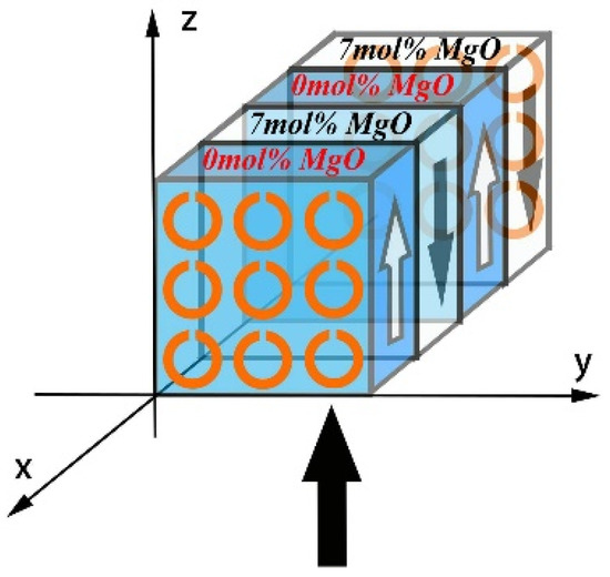
Figure 1.
A schematic diagram of the MPPC, which is composed of a one-dimensional IPPLNC and SRRs. The positive and negative domains of the MPPC are arranged periodically along the x-axis. The arrows along the positive and negative z-axes indicate the positive and negative domains, respectively. The Mg concentrations in the positive and negative domains are 0 mol% and 7 mol%, respectively. The bottom arrow indicates the direction of y-polarized EM wave propagation. Here, only two periods of the MPPC have been shown.
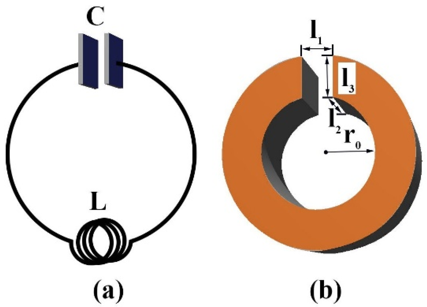
In Figure 1, the positive and negative domains of the MPPC are arranged periodically along the x-axis. We denote a and b as the thicknesses of positive and negative domains, respectively. Then, the period of domains is Λ = a + b, and the duty cycle is r = a/b. The thickness of the MPPC is b0 along the x-axis. The SRRs are installed on the opposite sides of the MPPC along the x-axis, and the gap directions of the SRRs are identical. The SRR can be described as an equivalent LC oscillator with the capacitance C of the SRR gap, a practical inductance L, and resistance R [28]. Figure 2a,b show the comparison of an equivalent LC circuit and a metallic SRR; the parameters of SRR are marked in Figure 2b: the gap size l1, the thickness l2, and the width l3, radius r0 [29]. The bottom arrow indicates that a y-polarized EM wave propagates through MPPC along the z-axis. According to Faraday’s law of electromagnetic induction, currents can be induced by the magnetic field of the EM wave in the SRRs. This result in an attractive Ampère force between the SRRs, and MPPC is compressed periodically by the Ampère forces acting between the SRRs. For identical rings sharing a common axis and carrying currents, the force acting between them has only the axial component, calculated as [30]

Figure 2.
Schematics of the analogy. (a) A usual LC circuit (with effective inductance L and the capacitance C). (b) SRR (with the gap size l1, the thickness l2, the width l3, and the radius r0).
Here, K and E are the complete elliptic integrals of the first and second kind, ( is the relative permittivity of the material filled in the SRR gap, , and .) is the impedance of the SRR, is magnetic flux. We assume additional forces between the SRRs in the neighbouring columns can be neglected. Because of the attractive Ampère forces between the SRRs, the stress is created on the cross-sectional area of the MPPC along the x-axis, that is,
where, S is the cross-sectional area of the MPPC along the x-axis, m is the number of SRRs, and T0 is the periodic stress which is applied to the cross-sectional area S of the MPPC along the x-axis. The stress can excite a transverse electric polarization due to the piezoelectric effect. And the periodic electric field of the EM wave can excite a longitudinal superlattice vibration in response to the piezoelectric effect and periodic modulation of the piezoelectric coefficients. These cause electric, magnetic, and sound fields to be coupled together in the MPPC. The piezoelectric and Maxwell equations of the three fields’ coupling are written as follows [31]:
here,
Here, T1, S1, E2 and D2 are the stress, strain, electric field, and electric displacement, respectively, and they are functions of both position and time. (x), e22(x), d22(x), and (x) are the elastic, piezoelectric stress, piezoelectric strain, and dielectric coefficients, respectively, and they are periotic functions of the position. is the permeability of vacuum. Here, the damping of materials has been considered.
Equations (3) and (4) imply the principle that the periotic stress T0 and y-polarized EM wave create the longitudinal superlattice vibration S1, and which is coupled to the incoming y-polarized EM wave. Equation (4) implies that the periotic stress T0 and longitudinal superlattice vibration S1 can excite an additional electric polarization because of the piezoelectric effect. We assume that there is no free charge in the MPPC,
Applying Equation (4) to Equation (9), we have:
Using Fourier transformation, the modulation functions are written as:
Here,
Applying Equations (11)–(19) to Equation (10), we have:
here,
. Substitution of Equation (20) into Equation (3), the dielectric function is obtained as:
Here, is the equivalent elastic coefficient. is the function of the x-coordinate and frequency ω. Then, the equivalent elastic coefficient of the positive domain is written as:
and the equivalent elastic coefficient of the negative domain is written as:
The numerical simulation of the MPPC is based on the computing of the transmission coefficient [32,33]. According to Equations (25) and (26), we computed the transmission coefficient of the MPPC by use of the Transfer Matrix Method. It is derived as follows:
here:
and are the acoustic impedance of the positive and negative domains, and are the velocity of the acoustic wave of the positive and negative domains, and are the wave vectors of the acoustic wave of the positive and negative domains, respectively.
3. Results and Discussion
According to the transmission function, we can obtain the physical information required to study the transmission properties of sound waves in the MPPC [32,33]. In the MPPC, ferroelectric domains of the IPPLNC are periodically reversed along x-axis and the ion-doped concentration of the positive and negative domains of IPPLN changes periodically. For the doped ion, we chose the Mg ion. The Mg ion concentrations of the positive and negative domains in the MPPC are 0 mol% and 7 mol% (see Figure 1), respectively. The reasons for doping concentration selection are as follows. Iyi et al. reconstructed the Mg-incorporation mechanism based on the Li vacancy model [25]. At first, the Mg ions replace the Nb sites (Nb on Li sites), maintain the ratio of [Li]/[Nb] at 0.94, and complete replacement takes place at 3 mol%. Further Mg ions were introduced into the Li sites, replacing the Li ions up to [Li]/[Nb] = 0.84. Beyond this point, the Mg ions enter the Nb and Li sites simultaneously, maintaining a constant [Li]/[Nb] ratio. There are two threshold concentrations during the incorporation of Mg ions in the lattice. The two threshold phenomena were proposed by Grabmaier et al. [34]. According to their results, the [Li]/[Nb] ratio is nearly constant, up to 3 mol% MgO doping, then decreases steeply up to 8 mol% MgO doping, followed by a sluggish decrease in [Li]/[Nb] ratio beyond this concentration. Abdi et al. reconstructed the Mg-incorporation model in the light of the Li and Nb vacancy model [35], which was proposed earlier by Donnerberg et al. [24]. The model predicts four successive concentration stages during the introduction of Mg ions in the lattice. This mechanism of Mg substitution is supported by the analysis of Raman scattering data. In the third stage of the defect model, Mg ions replace Li ions in their own natural sites with increasing Mg concentration from 2.46 to 5.15 mol%. Owing to the stronger bond strength of Mg–O bonds compared with that of Li–O bonds [35], the elastic properties of MgO-doped LiNbO3 increase with increasing Mg concentration.
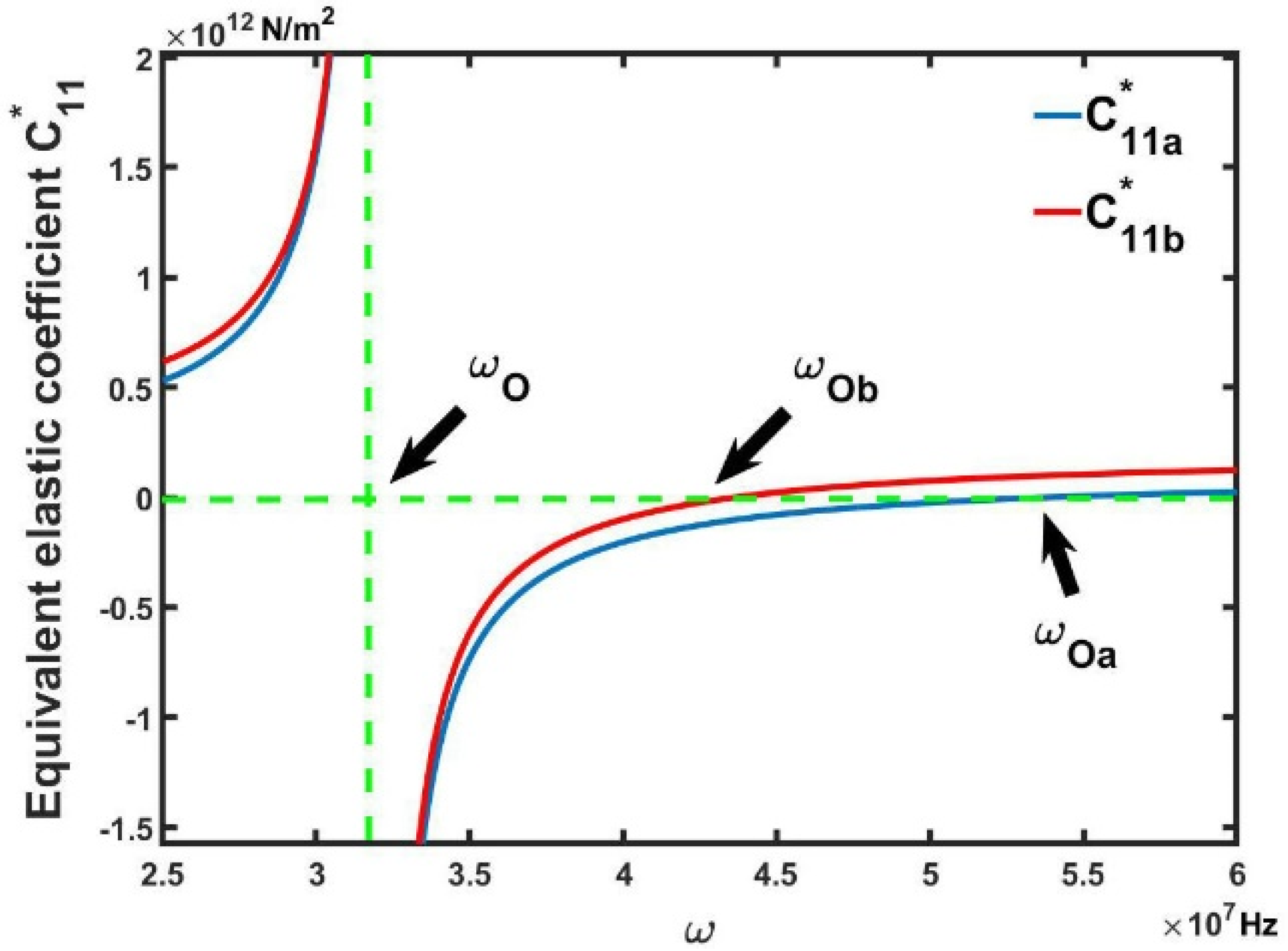
From the above results, Mg ion concentrations of the positive and negative domains in the MPPC of 0 mol% and 7 mol% were chosen in order to increase the difference between elastic coefficients. By use of Equations (24) and (25), the first-order equivalent elastic coefficients and (n = 1) of the positive and negative domains in the MPPC are plotted in Figure 3. Because the damping of the material is not considered, Figure 3 only shows the real parts of the equivalent elastic coefficients, and and are represented by the blue and red lines, respectively. In this paper, the material parameters of the positive domain in the MPPC are chosen from Ref. [31]: = 2.03 × 10¹¹ N/m2, = 2.50 C/m2, = 4.700 × 10³ kg/m3, = 44.00. The proper values of the material parameters of the negative domain in the MPPC are chosen as follows [26,27,36,37,38]: = 3.00 × 10¹¹ N/m2, = 2.32 C/m2, = 4.630 × 10³ kg/m3, = 20.00. The other parametersinclude: the period Λ = 2 × 10⁻⁵ m, the number of the period N = 20, the duty cycle r = a/b = 3, m = 1, r0 = 5.00 × 10⁻³ m, S0 = 7.85 × 10⁻⁵ m2, S = 1.00 × 10⁻⁴ m2, the suitable values of the complete elliptic integrals of the first K and second kind E are chosen from Refs. [39,40,41]
here
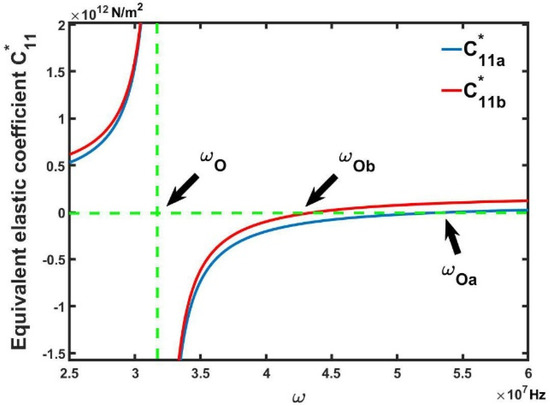
Figure 3.
Calculated the first−order (n = 1) equivalent elastic coefficient curves of the MPPC. The solid lines represent the real part of the equivalent elastic coefficients and . The functions exhibit negative values in the frequency gaps (, ) and (, ).
Figure 3 shows the two elastic anomalies near the resonance frequencies = 3.19 × 10⁷ Hz. The real part of the elastic coefficients exhibits negative values in the frequency gaps (, ) and (, ). Here, , , and can be obtained by setting = 0 and = 0 in Equations (24) and (25). The enhancement of the piezoelectric effect generates the frequency-independent elastic anomalies, which stems from the fact that MPPC is compressed periodically by the Ampère forces acting between the SRRs. This result was first proposed theoretically and was not experimentally observed. While temperature-independent elastic modulus (Elinvar) and thermal expansion (Invar) properties have been experimentally investigated, and the research found that the elastic modulus of Fe-36Ni changes abnormally near a certain temperature [42].
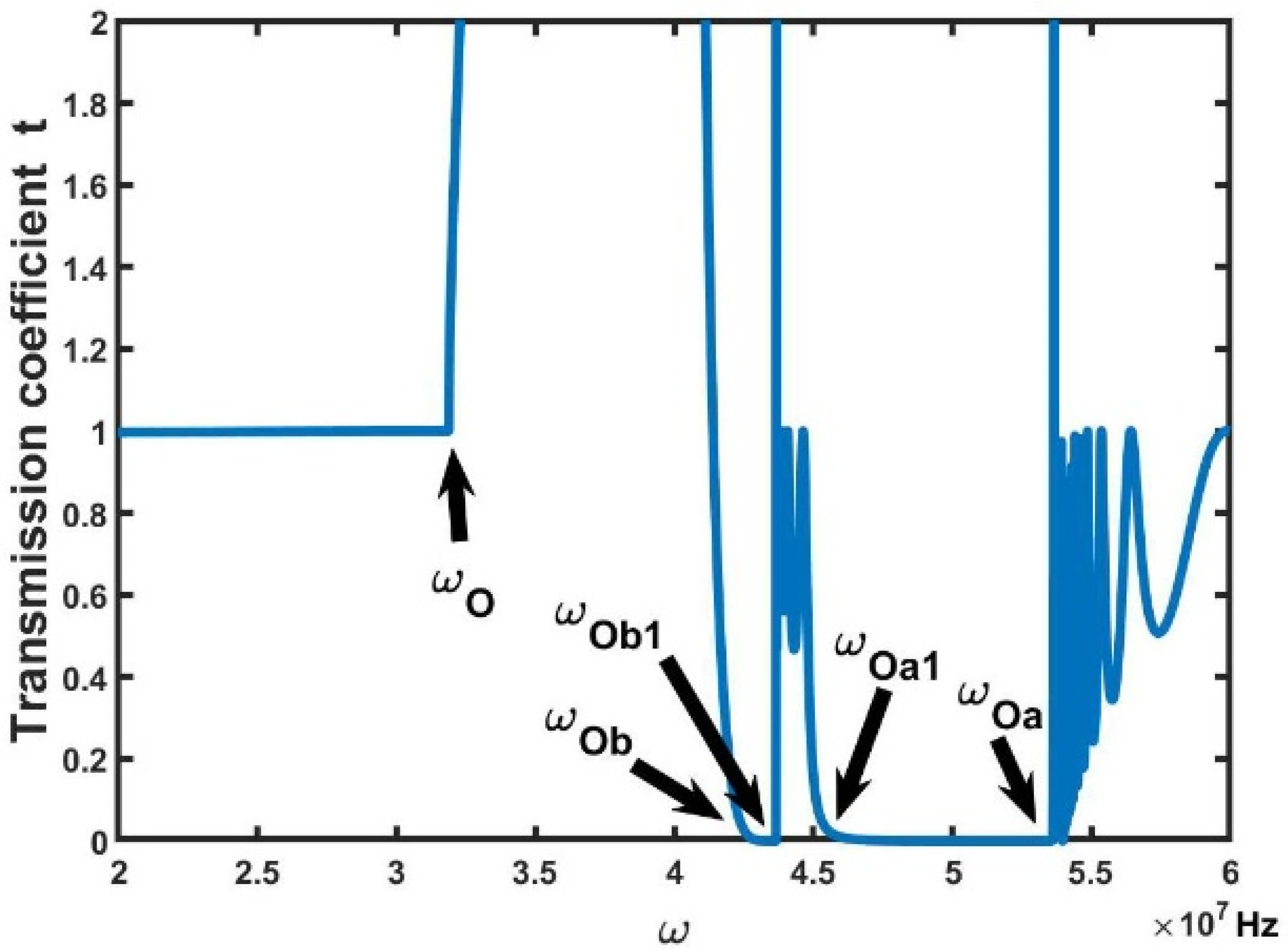
Now, let us address their influence on the transmission properties of the sound waves in the MPPC. We know that the elastic coefficient plays an important role in the computing of the Transfer Matrix. Therefore, the two elastic anomalies can influence the transmission spectrum, which was computed by using the Transfer Matrix. From Equation (26), the transmission coefficient t is plotted in Figure 4. The physical origin of Equation (26) can be understood at the micro-scale from the classical wave theory to describe the Bragg resonances, based on the scattering of mechanical waves propagating within the phononic crystal [43].
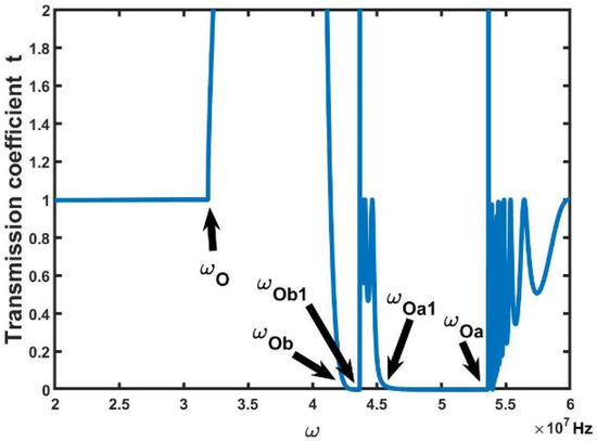
Figure 4.
Transmission coefficient curves of the MPPC. There are two MPBGs (, ) and (, ) in the transmission spectrum. They result from an enhancement of the piezoelectric effect, which originates from the Ampère forces acting between the SRRs. When the longitudinal waves propagate along the x-axis of the MPPC, it will be strongly reflected as long as their frequency lies in the frequency gaps.
As shown in Figure 4, corresponding to the resonance frequencies of elastic anomalies (see Figure 3), there are two frequency regions (, ) and (, ) of transmission coefficient t = 0 in the transmission spectrum of the MPPC, here = 4.56 × 10⁷ Hz, and = 4.36 × 10⁷ Hz. In the two frequency regions, longitudinal waves are forbidden to propagate through MPPC along x-axis. In the frequency region (), transmission coefficient t 0 because the absolute values of the elastic coefficients of positive and negative domains are approximately equal. According to our simulation results, the two MPBGs cannot be generated in other piezoelectric phononic crystals [6,7,8,9,10]. If the SRRs are not placed on the opposite sides of the MPPC along the x-axis, the MPBGs will not also be created near the resonance frequencies. These results are attributed to the coupling of the magnetic, acoustic and electric fields. Essentially, they are the results of an enhancement of the piezoelectric effect that originates from the Ampère forces acting between the SRRs. In addition, two frequency regions are called the multifield coupling phononic band gap (MPBG).
In addition to the results above, the MPPC can be used as a left-handed metamaterial. The permeability of the SRRs of the MPPC becomes negative value in some specific frequency range [28], and the dielectric function of the IPPLNC exhibits negative values near the resonance frequencies [44,45]. If the frequency gaps of the SRRs and IPPLNC have an overlap by adjusting the structure parameters, both the magnetic permeability and dielectric coefficient of the MPPC are negative, then the MPPC will become left-handed metamaterials with lots of peculiar properties [46,47,48].
As we have seen, according to specific applications, the gap width and frequency positions of MPBGs in the MPPC are conveniently tuned by adjusting many parameters of the MPPC, such as ion-doped concentration, the parameters of crystal, and the sizes of the SRRs. It is one of the important properties of the MPPC that the sound waves are forbidden to propagate through the MPBGs of the materials. This makes it possible for the MPPC to be used to shield the devices from harmful sound waves or noises. It is also beneficial to the miniaturization of the devices, as the wavelength of the sound waves is much larger than the size of the building blocks.
4. Conclusions
In summary, we designed the MPPC. In this MPPC, the ferroelectric domains of the IPPLNC are periodically reversed along the x-axis, and the ion-doped concentration of the positive and negative domains of IPPLNC changes periodically. Because of the change of ion-doped concentration, the properties of the MPPC change periodically, such as elastic, piezoelectric and dielectric properties. The SRRs of the MPPC periodically exert pressure on the crystal according to Faraday’s law of electromagnetic induction. The periodic pressures enhance the piezoelectric effect of the PPLN. Apart from the periodic Ampère forces, the longitudinal sound waves are excited by the electric field of the EM wave due to the piezoelectric effect. These cause the electric, magnetic, and sound fields to be coupled together. The multifield coupling leads to elastic anomalies that influence the transmission properties of the acoustic waves.
By calculating the transmission coefficient of the MPPC through the Transfer Matrix Method of the phononic crystal, we studied the influences of these changes on the transmission properties of acoustic waves. The two MPBGs that forbid the transmission of sound waves are shown in the transmission spectrum of the MPPC, which correspond to two elastic anomalies. These results are attributed to the coupling of the magnetic, acoustic, and electric fields and are essentially the result of an enhancement of the piezoelectric effect, which originates from the Ampère forces acting between the SRRs. The gap width and frequency positions of the MPPC are conveniently tuned by adjusting many parameters of the MPPC, such as ion-doped concentration, the parameters of crystal, and the sizes of the SRRs, to meet the need of application. We have analyzed the possibility of crystals as left-handed metamaterials. These basic studies provide guidance toward the application of the MPPC in devices that apply sound waves. It is also beneficial to the miniaturization of devices, as the wavelength of sound waves is much larger than the size of the building blocks.
Author Contributions
W.-C.B.: ideas; formulation or evolution of overarching research goals and aims; management and coordination responsibility for the research activity planning and execution; designing computer programs; development or design of methodology. Y.C.: development or design of methodology; creation of models; designing computer programs. B.-H.Z.: application of statistical, mathematical, computational, or other formal techniques to analyze or synthesize study data. J.-L.L.: preparation, creation and/or presentation of the published work, specifically writing the initial draft (including substantive translation). G.-X.L.: preparation, creation, and presentation of the published work, specifically writing the initial draft (including substantive translation). H.Z.: conducting the research and investigation process, data collection; programming. H.-Z.Z.: provision of study materials; management and coordination responsibility for the research activity planning and execution. H.H.: conducting a research and investigation process and data collection. All authors have read and agreed to the published version of the manuscript.
Funding
This work is supported by the Hunan Provincial Natural Science Foundation of China (Grant No. 2020JJ4555) and the Natural Science Foundation of Hunan Province of China (Grant No. 2019jj50563).
Institutional Review Board Statement
Not applicable.
Informed Consent Statement
Not applicable.
Data Availability Statement
Not applicable.
Conflicts of Interest
We declare that we have no financial and personal relationships with other people or organizations that can inappropriately influence our work; there is no professional or other personal interest of any nature or kind in any product, service or company that could be construed as influencing the position presented in, or the review of, the manuscript entitled “Theoretical investigation of magneto-electro-elastic piezoelectric phononic crystal”.
References
- Hepplestone, S.P.; Srivastava, G.P. Hypersonic modes in nanophononic semiconductors. Phys. Rev. Lett. 2008, 101, 105502. [Google Scholar] [CrossRef] [Green Version]
- Yablonovitch, E. Inhibited spontaneous emission in solid-state physics and electronics. Phys. Rev. Lett. 1987, 50, 2059–2062. [Google Scholar] [CrossRef] [PubMed] [Green Version]
- John, S. Strong localization of photons in certain disordered dielectric superlattices. Phys. Rev. Lett. 1987, 58, 2486–2489. [Google Scholar] [CrossRef] [PubMed] [Green Version]
- Mesquida, A.A.; Otero, J.A.; Ramos, R.R. Wave propagation in layered piezoelectric structures. J. Appl. Phys 1998, 83, 4652–4659. [Google Scholar] [CrossRef]
- Wilm, M.; Ballandras, S.; Laude, V.; Pastureaud, T. A full 3D plane-wave-expansion model for 1–3 piezoelectric composite structures. J. Acoust. Soc. Am. 2002, 112, 943–952. [Google Scholar] [CrossRef] [Green Version]
- Liu, W.; Yu, G. Propagation of Transverse Wave for the piezoelectric radial phononic crystal annular plate in a fibonacci order. Shock. Vib. 2021, 2021, 3905426. [Google Scholar] [CrossRef]
- Li, Q.; Guo, Y.; Wang, Y.; Zhang, H. Band tunability of coupled elastic waves along thickness in laminated anisotropic piezoelectric phononic crystals. Crystals 2019, 9, 426. [Google Scholar] [CrossRef] [Green Version]
- Hong, J.; He, Z.Z.; Zhang, G.; Mi, C.W. Tunable bandgaps in phononic crystal microbeams based on microstructure, piezo and temperature effects. Crystals 2021, 11, 1029. [Google Scholar] [CrossRef]
- Mistewicz, K.; Jesionek, M.; Kim, H.J.; Hajra, S.; Kozioł, M.; Chrobok, Ł.; Wang, X.D. Nanogenerator for determination of acoustic power in ultrasonic reactors. Ultrason. Sonochem. 2021, 78, 105718. [Google Scholar] [CrossRef]
- Hu, R.; Wu, J.; Yang, Y.Z.; Wang, X.Y.; Jia, H.; Deng, K.; He, Z.J.; Zhao, H.P. Tunable composite waveguide based on piezoelectric phononic crystal. AIP Adv. 2019, 9, 045120. [Google Scholar] [CrossRef]
- Tiercelin, N.; Dusch, Y.; Preobrazhensky, V.; Pernod, P. Magnetoelectric memory using orthogonal magnetization states and magnetoelastic switching. J. Appl. Phys. 2011, 109, 726. [Google Scholar] [CrossRef]
- Fiebig, M. Revival of the magnetoelectric effect. J. Phys. D Appl. Phys. 2005, 38, 123. [Google Scholar] [CrossRef]
- Achenbach, J.D. Quantitative nondestructive evaluation. Int. J. Solids Struct. 2000, 37, 13–27. [Google Scholar] [CrossRef]
- Chen, J.Y.; Guo, J.H.; Pan, E. Wave propagation in magneto-electro-elastic multilayered plates with nonlocal effect. J. Sound Vib. 2017, 400, 550–563. [Google Scholar] [CrossRef]
- Ezzin, H.; Amor, M.B.; Ghozlen, M.H.B. Love waves propagation in a transversely isotropic piezoelectric layer on a piezomagnetic half-space. Ultrasonics 2016, 69, 83–89. [Google Scholar] [CrossRef]
- Hu, J.Y.; Yang, G.Y.; Shen, T.; Zhang, M.H.; Du, J.K. Bandgap tunability of surface acoustic waves in a two-dimensional magneto-electro-elastic phononic crystal. AIP Adv. 2021, 11, 065004. [Google Scholar] [CrossRef]
- Miranda, E.J.P.d., Jr.; Rodrigues, S.F.; Aranas, C., Jr.; Silva, H.V.C.d.; Silva, E.S.; Reis, G.S.; Paiva, A.E.M.; Santos, J.M.C.D. Modelling propagating bloch waves in magnetoelectroelastic phononic structures with Kagomé lattice using the improved plane wave expansion. Crystals 2020, 10, 586. [Google Scholar] [CrossRef]
- Deng, T.; Zhang, S.Z.; Gao, Y.W. A magnetic-dependent vibration energy harvester based on the tunable point defect in 2D magneto-elastic phononic crystals. Crystals 2019, 9, 261. [Google Scholar] [CrossRef] [Green Version]
- Tasson, M.; Legal, H.; Gay, J.S.; Peuzin, J.C.; Lissalde, F.S. Piezoelectric study of poling mechanism in lithium niobate crystals at temperature close to the curie point. Ferroelectrics 1976, 13, 479–481. [Google Scholar] [CrossRef]
- Magel, G.A.; Fejer, M.M.; Byer, R.L. Quasi-phase-matched second-harmonic generation of blue light in periodically poled LiNbO3. Appl. Phys. Lett. 1990, 56, 108–110. [Google Scholar] [CrossRef] [Green Version]
- Evlanova, I.I.N.N.F.; Gliko, O.A.; Lavrishchev, S.V. Study of periodically poled Czochralski-grown Nd:Mg:LiNbO3 by chemical etching and X-ray microanalysis. J. Cryst. Growth 1991, 181, 160–164. [Google Scholar]
- Hammoum, R.; Fontana, M.D.; Gilliot, M.; Bourson, P.; Kokanyan, E.P. Site spectroscopy of Hf doping in Hf-doped LiNbO3 crystals. Solid State Commun. 2009, 149, 1967. [Google Scholar] [CrossRef]
- Lorenzo, A.; Jaffrezic, H.; Roux, B.; Boulon, G.; Garcia-Sole, J. Lattice location of rare-earth ions in LiNbO3. Appl. Phys. Lett. 1995, 67, 3735. [Google Scholar] [CrossRef]
- Donnerberg, H.; Tomlinson, S.M.; Catlow, C.R.A.; Schirmer, O.F. Computer-simulation studies of extrinsic defects in LiNbO3 crystals. Phys. Rev. B 1991, 44, 4877. [Google Scholar] [CrossRef]
- Iyi, N.; Kitamura, K.; Yajima, Y.; Kimura, S.; Furukawa, Y.; Sato, M. Defect structure model of MgO-doped LiNbO3. J. Solid State Chem. 1995, 118, 148–152. [Google Scholar] [CrossRef]
- Kushibiki, J.; Kobayashi, T.; Ishiji, H.; Chubachi, N. Elastic properties of 5−mol% MgO doped LiNbO3 crystals measured by line focus beam acoustic microscopy. Appl. Phys. Lett. 1992, 61, 2164–2166. [Google Scholar] [CrossRef]
- Xue, D.F.; He, X.K. Dopant occupancy and structural stability of doped lithium niobate crystals. Phys. Rev. B 2006, 73, 064113. [Google Scholar] [CrossRef]
- Zharov, A.A.; Shadrivov, I.V.; Kivshar, Y.S. Nonlinear properties of left-handed metamaterials. Phys. Rev. Lett. 2003, 91, 037401. [Google Scholar] [CrossRef] [Green Version]
- Bai, W.C.; Zhao, D.; Lan, Z.J.; Zhang, H.; Zhang, H.Z.; Yuan, L. Theoretical investigation of magneto-electro-elastic metamaterials. Solid State Commun. 2020, 310, 113850. [Google Scholar] [CrossRef]
- Landau, L.D.; Lifschitz, E.M. Electrodynamics of Continuous Media; Pergamon Press: Oxford, UK, 1984. [Google Scholar]
- Auld, B.A. Acoustic Fields and Waves in Solids; Wiley: New York, NY, USA, 1973. [Google Scholar]
- Camley, R.E.; Djafari-Rouhani, B.; Dobrzynski, L.; Maradudin, A.A. Transverse elastic waves in periodically layered infinite and semi-infinite media. Phys. Rev. B 1983, 27, 7318–7329. [Google Scholar] [CrossRef]
- Djafari-Rouhani, B.; Dobrzynski, L.; Duparc, O.H.; Camley, R.E.; Maradudin, A.A. Sagittal elastic waves in infinite and semi-infinite superlattices. Phys. Rev. B 1983, 28, 1711–1720. [Google Scholar] [CrossRef]
- Grabmaier, B.C.; Otto, F. Growth and investigation of MgO-doped LiNbO3. J. Cryst. Growth 1986, 79, 682. [Google Scholar] [CrossRef]
- Abdi, F.; Aillerie, M.; Bourson, P.; Fontana, M.D. Defect structure in Mg-doped LiNbO3LiNbO3: Revisited study. J. Appl. Phys. 2009, 106, 033519. [Google Scholar] [CrossRef]
- Kushibiki, J.; Kobayashi, T.; Ishiji, H.; Jen, C.K. Surface-acoustic-wave properties of MgO-doped LiNbO3 single crystals measured by line-focus-beam acoustic microscopy. J. Appl. Phys. 1999, 85, 7863. [Google Scholar] [CrossRef]
- Bai, W.C.; Jiang, L.; Zhang, H.Z.; Ma, G.H. Influence of Mg doping on the dielectric properties of MgO-doped lithium niobate. Phys. B 2011, 406, 1567. [Google Scholar] [CrossRef]
- Xue, D.; Kitamura, K. Dielectric characterization of the defect concentration in lithium niobate single crystals. Solid State Commun. 2002, 122, 537. [Google Scholar] [CrossRef]
- Qi, F.; Zhang, H. Inequalities of the complete elliptic integrals. Tamkang J. Math. 1995, 3, 165–169. [Google Scholar] [CrossRef]
- Cerone, P.; Dragomir, S.S. Lobatto type quadrature rules for functions with bounded derivative. Math. Inequal Appl. 2003, 3, 197–209. [Google Scholar] [CrossRef]
- Guo, B.N.; Feng, Q. Some bounds for the complete elliptic integrals of the first and the second kinds. Math. CA 2009, 18, 2787–2790. [Google Scholar] [CrossRef]
- Guillaume, C.E. The anomaly of the nickel-steels. Proc. Phys. Soc. 1920, 32, 374–404. [Google Scholar] [CrossRef]
- Olsson, R.H., III; El-Kady, I. Microfabricated Phononic Crystal Devices and Applications. Meas. Sci. Technol. 2009, 20, 012002. [Google Scholar] [CrossRef]
- Bai, W.C.; Zhang, H.; Jiang, L.; Zhang, H.Z.; Zhang, L.Q. Theoretical investigation of phonon-polariton modes in undoped and ion-doped PPLN crystals. Solid State Commun. 2011, 151, 1261–1265. [Google Scholar] [CrossRef]
- Bai, W.C.; Lan, Z.J.; Zhang, H.; Jiang, L. Theoretical investigation of the phonon-polariton mode in Czochralski grown piezoelectric superlattice. Superlattices Microstruct. 2016, 97, 167–175. [Google Scholar] [CrossRef]
- Pendry, J.B.; Holden, A.J.; Stewart, W.J.; Youngs, I. Extremely low frequency plasmons in metallic meso structures. Phys. Rev. Lett. 1996, 76, 4773. [Google Scholar] [CrossRef] [Green Version]
- Veselago, V.G.; Lebedev, P.N. The electrodynamics of substances with simultaneously negative values of ε and µ. Sov. Phys. Usp. 1968, 10, 509–514. [Google Scholar] [CrossRef]
- Parazzoli, C.G.; Greegor, R.B.; Li, K.; Koltenbah, B.E.C.; Tanielian, M. Experimental verification and simulation of negative index of refraction using Snell’s law. Phys. Rev. Lett. 2003, 90, 107401. [Google Scholar] [CrossRef] [Green Version]

Publisher’s Note: MDPI stays neutral with regard to jurisdictional claims in published maps and institutional affiliations. |
© 2022 by the authors. Licensee MDPI, Basel, Switzerland. This article is an open access article distributed under the terms and conditions of the Creative Commons Attribution (CC BY) license (https://creativecommons.org/licenses/by/4.0/).