
Kinetics and Selectivity Study of Fischer–Tropsch Synthesis to C5+ Hydrocarbons: A Review


Abstract
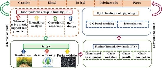
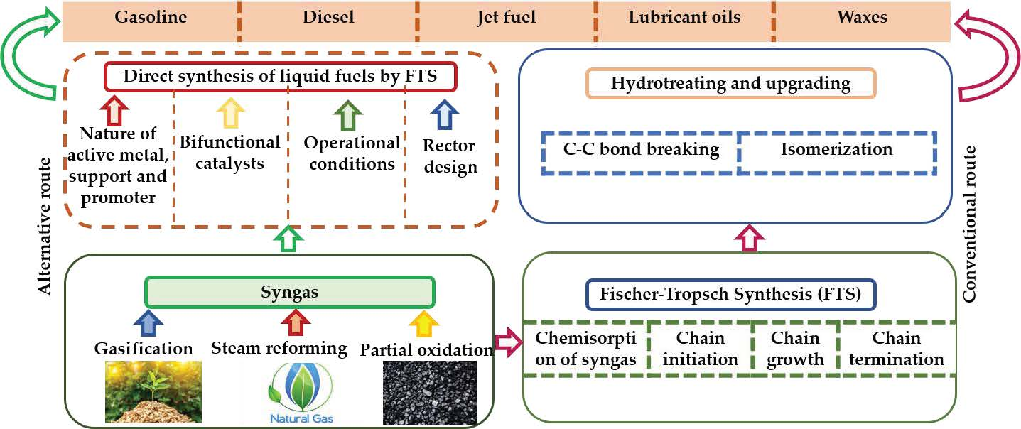
1. Introduction
2. Mechanisms of FTS
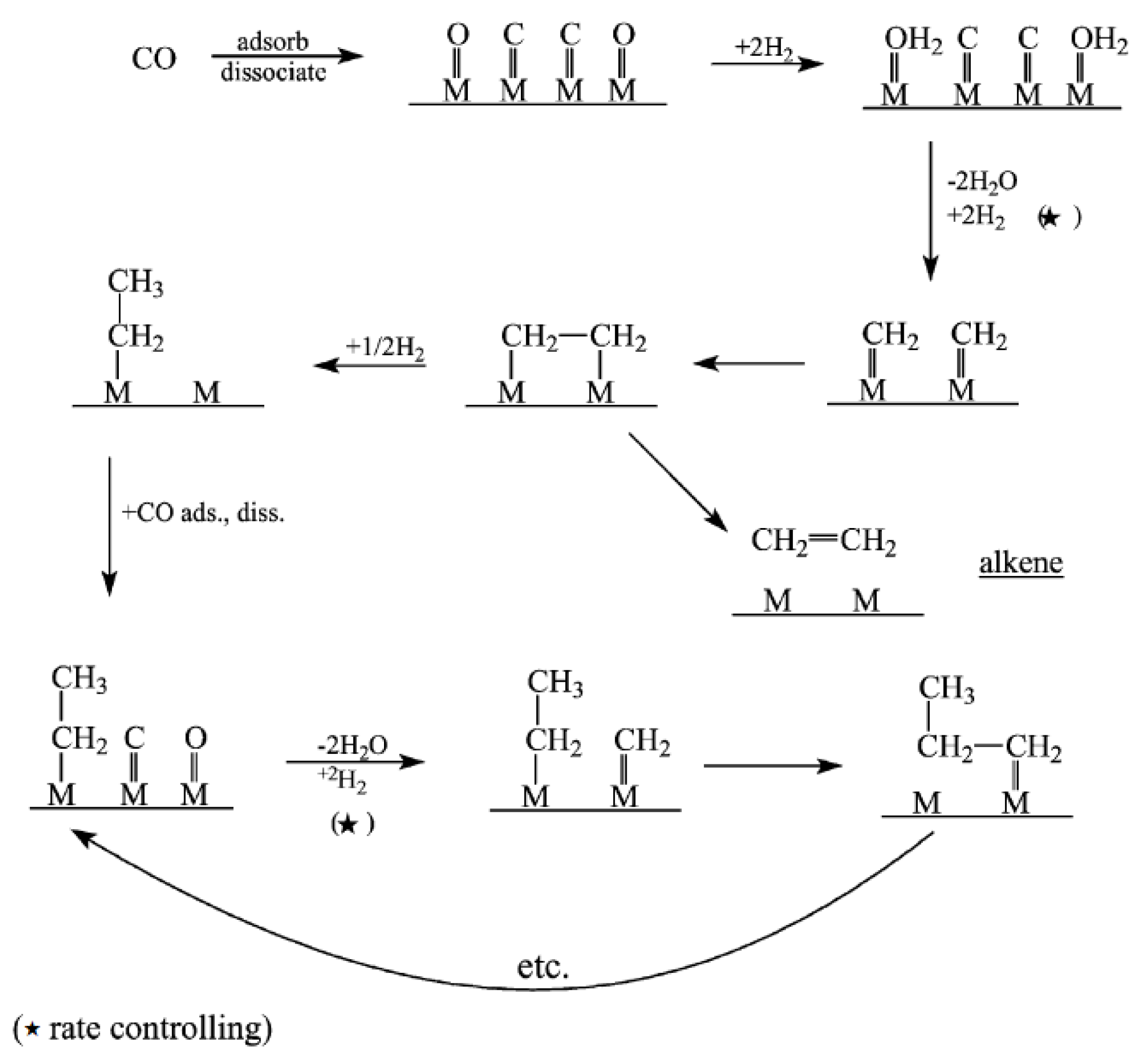
2.1. Carbide Mechanism
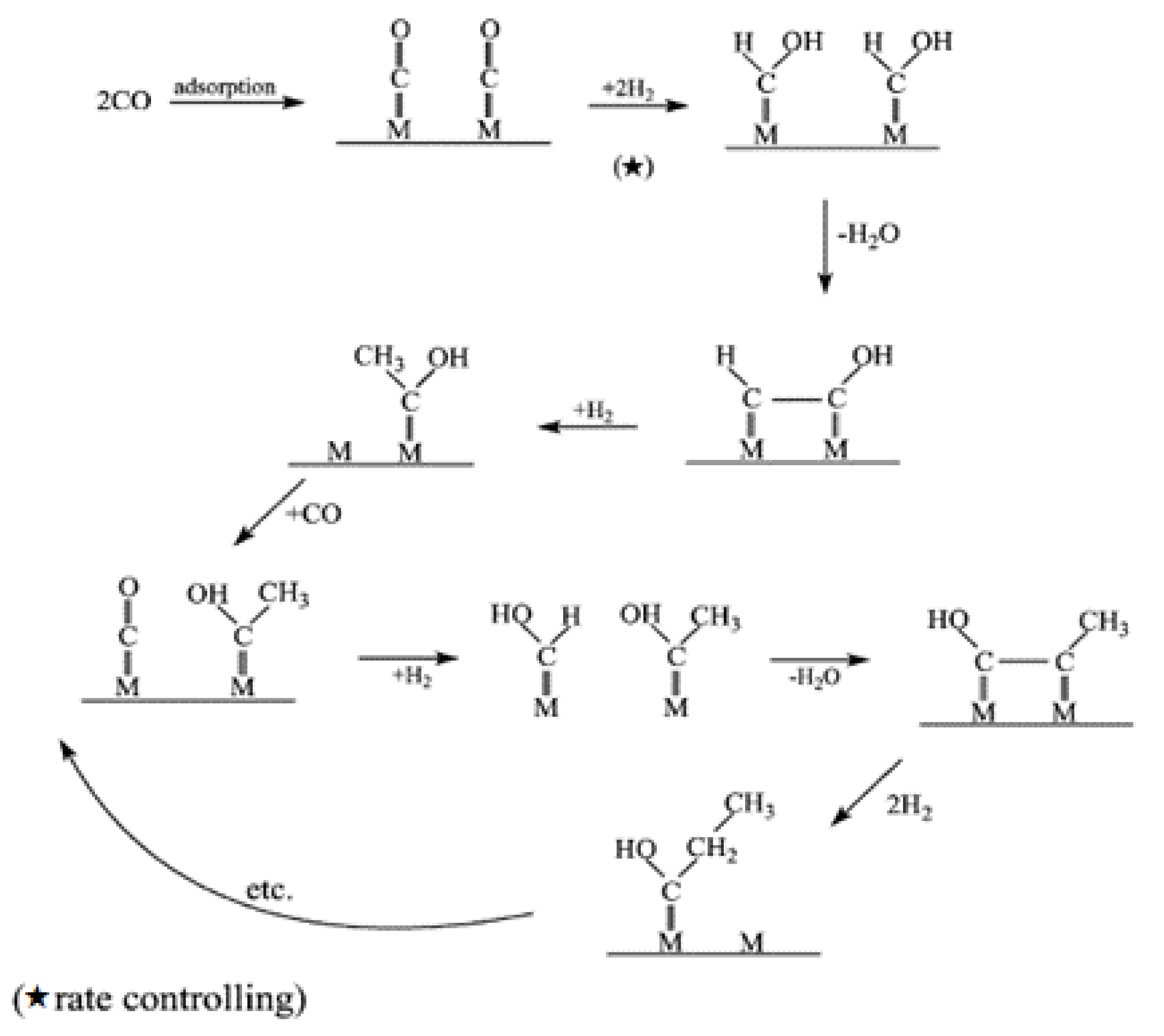
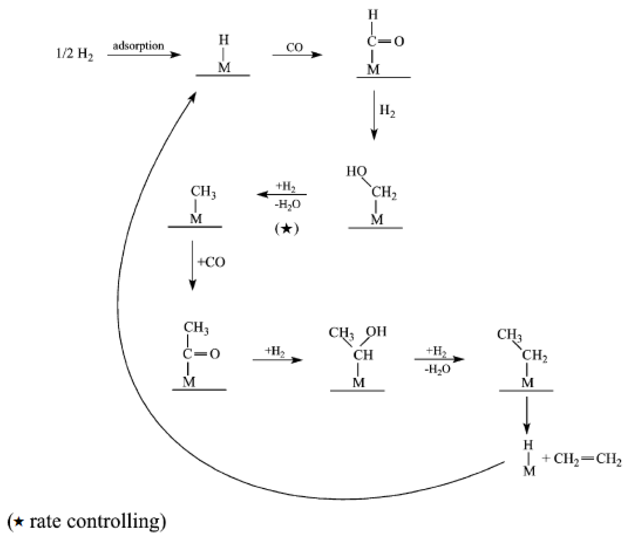
2.2. Enol (Oxygenate) Mechanism
2.3. CO Insertion Mechanism
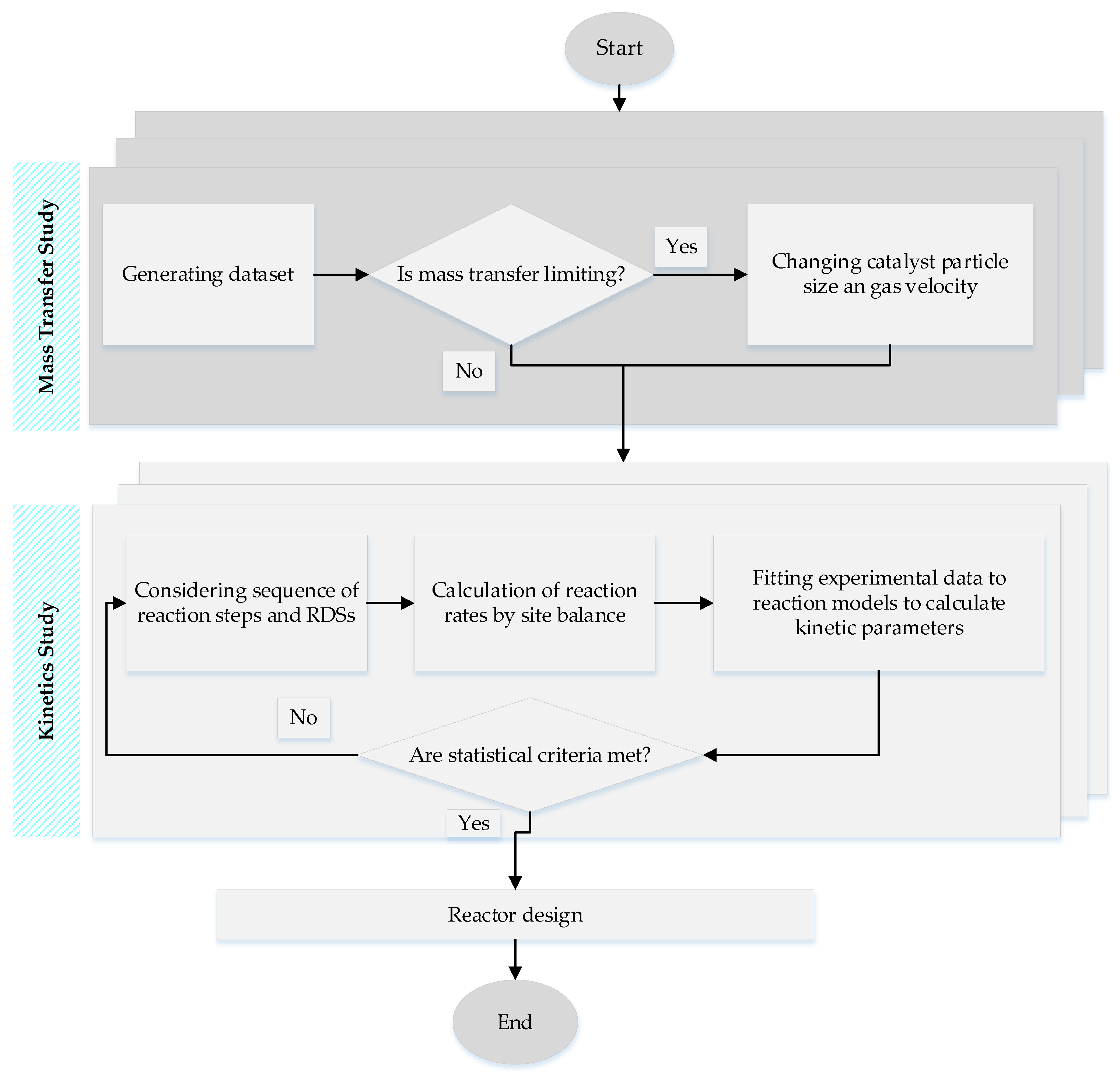
3. Kinetics of FTS
4. Catalysts of FTS
5. Support Materials for FTS Catalyst
5.1. Alumina as a Support for FTS
5.2. Silica-Supported Catalyst for FTS
5.3. Carbon-Based Supports for FTS
5.4. Other Support Materials for FTS
6. Catalyst Preparation
7. Catalyst Characterization
7.1. Diffraction-Based Characterizations
7.2. Spectroscopy-Based Techniques
7.3. Microscopy Based Characterizations
7.4. Thermal Methods
8. Selectivity of Products towards Liquid Fuels in FTS
8.1. Effects of the Nature of Active Components, Support, and the Promoters
8.2. Effects of Process Conditions
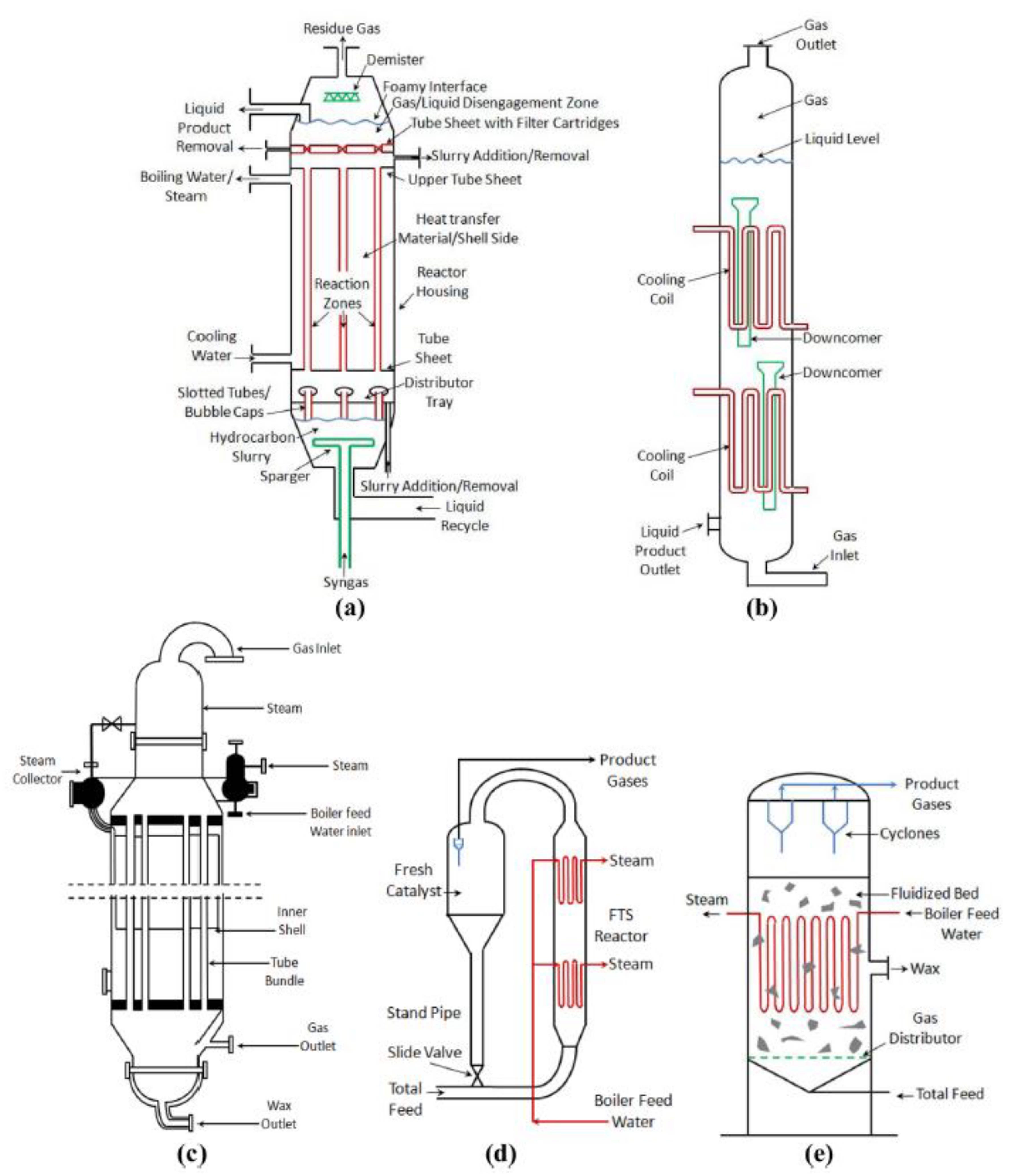
8.3. Effects of Reactor Design
9. Tuning Products’ Selectivity by Zeolites
10. Deactivation of the Catalysts during FTS
- The first possible mechanism is transformation of the active phases of Fe (iron carbides (such as χ-carbide, ε-carbide, ε’-carbide and metallic iron) to fewer active phases (magnetite and other types of iron carbides).
- The second postulated reason is the deposition of carbonaceous materials such as coke, graphitic and amorphous carbon. These materials decrease the effective contact between syngas molecules and the active sites of the catalyst for products formation.
- Sintering, the loss of catalytic surface area due to ripening or migration and coalescence of the iron phase under reaction conditions can be another reason for deactivation of iron catalysts.
- It is postulated that the sulfur compounds, which are present in most of the industrial syngas feeds, can cause the deactivation of the catalyst during FT reaction.
11. Conclusions
Funding
Acknowledgments
Conflicts of Interest
References
- Hu, J.; Yu, F.; Lu, Y. Application of Fischer–Tropsch Synthesis in Biomass to Liquid Conversion. Catalysts 2012, 2, 303–326. [Google Scholar] [CrossRef]
- Vosloo, A.C. Fischer–Tropsch: A futuristic view. Fuel Process. Technol. 2001, 71, 149–155. [Google Scholar] [CrossRef]
- Ripfel-Nitsche, K.; Hofbauer, H.; Rauch, R.; Goritschnig, M.; Koch, R.; Lehner, P.; Koch, M.; Kiennemann, A. BTL–Biomass to Liquid (Fischer Tropsch Process at the Biomass Gasifier in Güssing. In Proceedings of the 15th European Biomass Conference and Exhibition, Berlin, Germany, 7–11 May 2007. [Google Scholar]
- Choi, G.N.; Kramer, S.J.; Tam, S.T.; Fox, J.M. Design/Economics of a Natural Gas Based Fischer–Tropsch Plant. In Proceedings of the Spring National Meeting, Houston, TX, USA, 19–23 March 1996. [Google Scholar]
- Van Der Laan, G.P.; Beenackers, A.A.C.M. Kinetics and Selectivity of the Fischer–Tropsch Synthesis: A Literature Review. Catal. Rev. 1999, 41, 255–318. [Google Scholar] [CrossRef]
- Vallejo, D.F.R.; De Klerk, A. Improving the Interface between Fischer–Tropsch Synthesis and Refining. Energy Fuels 2013, 27, 3137–3147. [Google Scholar] [CrossRef]
- Krylova, A.Y. Products of the Fischer–Tropsch synthesis (A Review). Solid Fuel Chem. 2014, 48, 22–35. [Google Scholar] [CrossRef]
- Mousavi, S.; Zamaniyan, A.; Irani, M.; Rashidzadeh, M. Generalized kinetic model for iron and cobalt based Fischer–Tropsch synthesis catalysts: Review and model evaluation. Appl. Catal. A Gen. 2015, 506, 57–66. [Google Scholar] [CrossRef]
- Khodakov, A.Y.; Chu, W.; Fongarland, P. Advances in the Development of Novel Cobalt Fischer–Tropsch Catalysts for Synthesis of Long-Chain Hydrocarbons and Clean Fuels. Chem. Rev. 2007, 107, 1692–1744. [Google Scholar] [CrossRef] [PubMed]
- dos Santos, R.G.; Alencar, A.C. Biomass-derived syngas production via gasification process and its catalytic conversion into fuels by Fischer Tropsch synthesis: A review. Int. J. Hydrog. Energy 2020, 45, 18114–18132. [Google Scholar] [CrossRef]
- Fischer, F.; Tropsch, H. The Synthesis of Petroleum at Atmospheric Pressures from Gasification Products of Coal. Brennst. Chem. 1926, 7, 97–104. [Google Scholar]
- Martinelli, M.; Gnanamani, M.K.; LeViness, S.; Jacobs, G.; Shafer, W.D. An overview of Fischer–Tropsch Synthesis: XtL processes, catalysts and reactors. Appl. Catal. A Gen. 2020, 608, 117740. [Google Scholar] [CrossRef]
- Davis, B.H. Fischer–Tropsch synthesis: Current mechanism and futuristic needs. Fuel Process. Technol. 2001, 71, 157–166. [Google Scholar] [CrossRef]
- Kummer, J.T.; Browning, L.C.; Emmett, P.H. Thermodynamic Calculations Concerning the Possible Participation of the Carbides of Iron as Intermediate in Fischer–Tropsch Synthesis. J. Chem. Phys. 1948, 16, 739. [Google Scholar] [CrossRef]
- Kummer, J.T.; DeWitt, T.W.; Emmett, P.H. Some Mechanism Studies on the Fischer–Tropsch Synthesis Using C14. J. Am. Chem. Soc. 1948, 70, 3632–3643. [Google Scholar] [CrossRef] [PubMed]
- Brady, R.C.; Pettit, R. Reactions of diazomethane on transition-metal surfaces and their relationship to the mechanism of the Fischer–Tropsch reaction. J. Am. Chem. Soc. 1980, 102, 6181–6182. [Google Scholar] [CrossRef]
- Maitlis, P.M. Fischer–Tropsch, organometallics, and other friends. J. Organomet. Chem. 2004, 689, 4366–4374. [Google Scholar] [CrossRef]
- Ciobica, I.I.; Kramer, G.G.J.; Ge, Q.; Neurock, M.; Van Santen, R.R. Mechanisms for Chain Growth in Fischer–Tropsch Synthesis over Ru(0001). J. Catal. 2002, 212, 136–144. [Google Scholar] [CrossRef]
- Broos, R.J.P.; Zijlstra, B.; Filot, I.A.W.; Hensen, E.J.M. Quantum-Chemical DFT Study of Direct and H- and C-Assisted CO Dissociation on the χ-Fe5C2 Hägg Carbide. J. Phys. Chem. C 2018, 122, 9929–9938. [Google Scholar] [CrossRef]
- Broos, R.J.; Klumpers, B.; Zijlstra, B.; Filot, I.A.; Hensen, E.J. A quantum-chemical study of the CO dissociation mechanism on low-index Miller planes of ϴ-Fe3C. Catal. Today 2020, 342, 152–160. [Google Scholar] [CrossRef]
- Van Helden, P.; van den Berg, J.-A.; Ciobîcă, I.M. Hydrogen-assisted CO dissociation on the Co(211) stepped surface. Catal. Sci. Technol. 2012, 2, 491–494. [Google Scholar] [CrossRef]
- Kummer, J.T.; Emmett, P.H. Fischer—Tropsch Synthesis Mechanism Studies. The Addition of Radioactive Alcohols to the Synthesis Gas. J. Am. Chem. Soc. 1953, 75, 5177–5183. [Google Scholar] [CrossRef]
- Kummer, J.T.; Podgurski, H.H.; Spencer, W.; Emmett, P.H. Mechanism Studies of the Fischer—Tropsch Synthesis. The Addition of Radioactive Alcohol. J. Am. Chem. Soc. 1951, 73, 564–569. [Google Scholar] [CrossRef]
- Pichler, H.; Schulz, H. Recent Findings in the Field of Synthesis of Hydrocarbons from CO and H2. Chem. Ing. Tech. 1970, 42, 1162–1174. [Google Scholar] [CrossRef]
- Eliason, S.; Bartholomew, C. Reaction and deactivation kinetics for Fischer–Tropsch synthesis on unpromoted and potassium-promoted iron catalysts. Appl. Catal. A Gen. 1999, 186, 229–243. [Google Scholar] [CrossRef]
- Atashi, H.; Siami, F.; Mirzaei, A.; Sarkari, M. Kinetic study of Fischer–Tropsch process on titania-supported cobalt–manganese catalyst. J. Ind. Eng. Chem. 2010, 16, 952–961. [Google Scholar] [CrossRef]
- Van Santen, R.R.; Markvoort, A.B.; Filot, I.A.W.; Ghouri, M.M.; Hensen, E.E. Mechanism and microkinetics of the Fischer–Tropsch reaction. Phys. Chem. Chem. Phys. 2013, 15, 17038–17063. [Google Scholar] [CrossRef]
- Yang, J.; Qi, Y.; Zhu, J.; Zhu, Y.-A.; Chen, D.; Holmen, A. Reaction mechanism of CO activation and methane formation on Co Fischer–Tropsch catalyst: A combined DFT, transient, and steady-state kinetic modeling. J. Catal. 2013, 308, 37–49. [Google Scholar] [CrossRef]
- Todic, B.; Ma, W.; Jacobs, G.; Davis, B.H.; Bukur, D.B. CO-insertion mechanism based kinetic model of the Fischer–Tropsch synthesis reaction over Re-promoted Co catalyst. Catal. Today 2014, 228, 32–39. [Google Scholar] [CrossRef]
- Zhang, Y.; Yao, Y.; Chang, J.; Lu, X.; Liu, X.; Hildebrandt, D. Fischer–Tropsch synthesis with ethene co-feeding: Experimental evidence of the CO-insertion mechanism at low temperature. AIChE J. 2020, 66, 17029. [Google Scholar] [CrossRef]
- Moazami, N.; Wyszynski, M.L.; Rahbar, K.; Tsolakis, A.; Mahmoudi, H. A comprehensive study of kinetics mechanism of Fischer–Tropsch synthesis over cobalt-based catalyst. Chem. Eng. Sci. 2017, 171, 32–60. [Google Scholar] [CrossRef]
- Méndez, C.I.; Ancheyta, J. Kinetic models for Fischer–Tropsch synthesis for the production of clean fuels. Catal. Today 2020, 353, 3–16. [Google Scholar] [CrossRef]
- Scott, H.F. Elements of Chemical Reaction Engineering; Prentice Hall Profesional: Upper Saddle River, NJ, USA, 2006. [Google Scholar]
- Yang, J.H.; Kim, H.-J.; Chun, D.H.; Lee, H.-T.; Hong, J.-C.; Jung, H. Mass transfer limitations on fixed-bed reactor for Fischer–Tropsch synthesis. Fuel Process. Technol. 2010, 91, 285–289. [Google Scholar] [CrossRef]
- Mansouri, M.; Atashi, H.; A Mirzaei, A.; Jangi, R. Kinetics of the Fischer–Tropsch synthesis on silica-supported cobalt-cerium catalyst. Int. J. Ind. Chem. 2013, 4, 1. [Google Scholar] [CrossRef]
- Sonal; Kondamudi, K.; Pant, K.K.; Upadhyayula, S. Synergistic Effect of Fe–Co Bimetallic Catalyst on FTS and WGS Activity in the Fischer–Tropsch Process: A Kinetic Study. Ind. Eng. Chem. Res. 2017, 56, 4659–4671. [Google Scholar] [CrossRef]
- Abbasi, M.; Mirzaei, A.A.; Atashi, H. The mechanism and kinetics study of Fischer‒Tropsch reaction over iron-nickel-cerium nano-structure catalyst. Int. J. Hydrog. Energy 2019, 44, 24667–24679. [Google Scholar] [CrossRef]
- Mirzaei, A.A.; Sarani, R.; Azizi, H.R.; Vahid, S.; Torshizi, H.O. Kinetics modeling of Fischer–Tropsch synthesis on the unsupported Fe-Co-Ni (ternary) catalyst prepared using co-precipitation procedure. Fuel 2015, 140, 701–710. [Google Scholar] [CrossRef]
- Marvast, M.A.; Sohrabi, M.; Zarrinpashne, S.; Baghmisheh, G. Fischer–Tropsch Synthesis: Modeling and Performance Study for Fe-HZSM5 Bifunctional Catalyst. Chem. Eng. Technol. 2005, 28, 78–86. [Google Scholar] [CrossRef]
- Atashi, H.; Mansouri, M.; Hosseini, S.H.; Khorram, M.; Mirzaei, A.A.; Karimi, M.; Mansouri, G. Intrinsic kinetics of the Fischer–Tropsch synthesis over an impregnated cobalt-potassium catalyst. Korean J. Chem. Eng. 2012, 29, 304–309. [Google Scholar] [CrossRef]
- Schulz, H.; Claeys, M. Recent Advances in Fischer Tropsch Synthesis. Appl. Catal. A Gen. 1999, 186, 1–2. [Google Scholar]
- Enger, B.C.; Holmen, A. Nickel and Fischer–Tropsch Synthesis. Catal. Rev. 2012, 54, 437–488. [Google Scholar] [CrossRef]
- Shafer, W.D.; Gnanamani, M.K.; Graham, U.M.; Yang, J.; Masuku, C.M.; Jacobs, G.; Davis, B.H. Fischer–Tropsch: Product Selectivity–The Fingerprint of Synthetic Fuels. Catalysts 2019, 9, 259. [Google Scholar] [CrossRef]
- Jahangiri, H.; Bennett, J.; Mahjoubi, P.; Wilson, K.; Gu, S. A review of advanced catalyst development for Fischer–Tropsch synthesis of hydrocarbons from biomass derived syn-gas. Catal. Sci. Technol. 2014, 4, 2210–2229. [Google Scholar] [CrossRef]
- De Smit, E.; Weckhuysen, B.M. The renaissance of iron-based Fischer–Tropsch synthesis: On the multifaceted catalyst deactivation behaviour. Chem. Soc. Rev. 2008, 37, 2758–2781. [Google Scholar] [CrossRef] [PubMed]
- Fischer, N.; Claeys, M. In situ characterization of Fischer–Tropsch catalysts: A review. J. Phys. D Appl. Phys. 2020, 53, 293001. [Google Scholar] [CrossRef]
- Claeys, M.; Dry, M.; van Steen, E.; du Plessis, E.; van Berge, P.; Saib, A.; Moodley, D. In situ magnetometer study on the formation and stability of cobalt carbide in Fischer–Tropsch synthesis. J. Catal. 2014, 318, 193–202. [Google Scholar] [CrossRef]
- Davis, B.H. Fischer–Tropsch Synthesis: Comparison of Performances of Iron and Cobalt Catalysts. Ind. Eng. Chem. Res. 2007, 46, 8938–8945. [Google Scholar] [CrossRef]
- Spivey, J.J.; Dooley, K.M. Catalysis; Royal Society of Chemistry: London, UK, 2007; Volume 19, ISBN 978-1-84755-522-9. [Google Scholar]
- Pham, H.N.; Nowicki, L.; Xu, J.; Datye, A.K.; Bukur, D.B.; Bartholomew, C. Attrition Resistance of Supports for Iron Fischer–Tropsch Catalysts. Ind. Eng. Chem. Res. 2003, 42, 4001–4008. [Google Scholar] [CrossRef]
- Soled, S.L.; Iglesia, E.; Fiato, R.A.; Baumgartner, J.E.; Vroman, H.; Miseo, S. Control of Metal Dispersion and Structure by Changes in the Solid-State Chemistry of Supported Cobalt Fischer–Tropsch Catalysts. Top. Catal. 2003, 26, 101–109. [Google Scholar] [CrossRef]
- Ding, F.; Zhang, A.; Liu, M.; Zuo, Y.; Li, K.; Guo, X.; Song, C. CO2 Hydrogenation to Hydrocarbons over Iron-based Catalyst: Effects of Physicochemical Properties of Al2O3 Supports. Ind. Eng. Chem. Res. 2014, 53, 17563–17569. [Google Scholar] [CrossRef]
- Xie, T.; Wang, J.; Ding, F.; Zhang, A.; Li, W.; Guo, X.; Song, C. CO2 hydrogenation to hydrocarbons over alumina-supported iron catalyst: Effect of support pore size. J. CO2 Util. 2017, 19, 202–208. [Google Scholar] [CrossRef]
- Keyvanloo, K.; Mardkhe, M.K.; Alam, T.M.; Bartholomew, C.H.; Woodfield, B.F.; Hecker, W.C. Supported Iron Fischer–Tropsch Catalyst: Superior Activity and Stability Using a Thermally Stable Silica-Doped Alumina Support. ACS Catal. 2014, 4, 1071–1077. [Google Scholar] [CrossRef]
- Zhang, Y.; Xiong, H.; Liew, K.; Li, J. Effect of magnesia on alumina-supported cobalt Fischer–Tropsch synthesis catalysts. J. Mol. Catal. A Chem. 2005, 237, 172–181. [Google Scholar] [CrossRef]
- Vosoughi, V.; Badoga, S.; Dalai, A.K.; Abatzoglou, N. Modification of mesoporous alumina as a support for cobalt-based catalyst in Fischer–Tropsch synthesis. Fuel Process. Technol. 2017, 162, 55–65. [Google Scholar] [CrossRef]
- Snel, R. Supported iron catalysts in Fischer–Tropsch synthesis: Influence of the preparation method. Ind. Eng. Chem. Res. 1989, 28, 654–659. [Google Scholar] [CrossRef]
- Satterfield, C.N. Heterogeneous Catalysis in Industrial Practice, 2nd ed.; McGraw-Hill: New York, NY, USA, 1991. [Google Scholar]
- Munirathinam, R.; Minh, D.P.; Nzihou, A. Effect of the Support and Its Surface Modifications in Cobalt-Based Fischer–Tropsch Synthesis. Ind. Eng. Chem. Res. 2018, 57, 16137–16161. [Google Scholar] [CrossRef]
- Alothman, Z.A. A Review: Fundamental Aspects of Silicate Mesoporous Materials. Materials 2012, 5, 2874–2902. [Google Scholar] [CrossRef]
- Cano, L.A.; Cagnoli, M.V.; Bengoa, J.F.; Alvarez, A.M.; Marchetti, S.G. Effect of the activation atmosphere on the activity of Fe catalysts supported on SBA-15 in the Fischer–Tropsch Synthesis. J. Catal. 2011, 278, 310–320. [Google Scholar] [CrossRef]
- Cano, L.; Blanco, A.G.; Lener, G.; Marchetti, S.; Sapag, K. Effect of the support and promoters in Fischer–Tropsch synthesis using supported Fe catalysts. Catal. Today 2017, 282, 204–213. [Google Scholar] [CrossRef]
- Cano, L.; Cagnoli, M.; Fellenz, N.; Bengoa, J.; Gallegos, N.; Alvarez, A.; Marchetti, S. Fischer–Tropsch synthesis. Influence of the crystal size of iron active species on the activity and selectivity. Appl. Catal. A Gen. 2010, 379, 105–110. [Google Scholar] [CrossRef]
- Khodakov, A.Y.; Zholobenko, V.L.; Bechara, R.; Durand, D. Impact of aqueous impregnation on the long-range ordering and mesoporous structure of cobalt containing MCM-41 and SBA-15 materials. Microporous Mesoporous Mater. 2005, 79, 29–39. [Google Scholar] [CrossRef]
- Bezemer, G.; Van Laak, A.; Van Dillen, A.; De Jong, K. Cobalt supported on carbon nanofibers—A promising novel Fischer–Tropsch catalyst. Pharmacogenetics 2004, 147, 259–264. [Google Scholar] [CrossRef]
- Bezemer, G.L.; Bitter, J.H.; Kuipers, H.P.C.E.; Oosterbeek, H.; Holewijn, J.E.; Xu, X.; Kapteijn, F.; Van Dillen, A.A.J.; De Jong, K.P. Cobalt Particle Size Effects in the Fischer–Tropsch Reaction Studied with Carbon Nanofiber Supported Catalysts. J. Am. Chem. Soc. 2006, 128, 3956–3964. [Google Scholar] [CrossRef] [PubMed]
- Cheng, K.; Ordomsky, V.V.; Virginie, M.; Legras, B.; Chernavskii, P.; Kazak, V.; Cordier, C.; Paul, S.K.; Wang, Y.; Khodakov, A.Y. Support effects in high temperature Fischer–Tropsch synthesis on iron catalysts. Appl. Catal. A Gen. 2014, 488, 66–77. [Google Scholar] [CrossRef]
- Teimouri, Z.; Salem, A.; Salem, S. Clean and new strategy for catalytic conversion of agriculture waste shells to activated carbon via microwave-assisted impregnation: Applied and eco-friendly aspect for decoloration of industrial corn syrup and process identifications. J. Environ. Chem. Eng. 2019, 7, 103161. [Google Scholar] [CrossRef]
- Luque, R.; De La Osa, A.R.; Campelo, J.M.; Romero, A.A.; Valverde, J.L.; Sanchez, P. Design and development of catalysts for Biomass-To-Liquid-Fischer–Tropsch (BTL-FT) processes for biofuels production. Energy Environ. Sci. 2011, 5, 5186–5202. [Google Scholar] [CrossRef]
- Abbaslou, R.M.M.; Soltan, J.; Dalai, A.K. Effects of nanotubes pore size on the catalytic performances of iron catalysts supported on carbon nanotubes for Fischer–Tropsch synthesis. Appl. Catal. A Gen. 2010, 379, 129–134. [Google Scholar] [CrossRef]
- Yu, G.; Sun, B.; Pei, Y.; Xie, S.; Yan, S.; Qiao, M.; Fan, K.; Zhang, X.; Zong, B. FexOy@C Spheres as an Excellent Catalyst for Fischer–Tropsch Synthesis. J. Am. Chem. Soc. 2010, 132, 935–937. [Google Scholar] [CrossRef] [PubMed]
- Tu, J.; Ding, M.; Zhang, Y.; Li, Y.; Wang, T.; Ma, L.; Wang, C.; Li, X. Synthesis of Fe3O4-nanocatalysts with different morphologies and its promotion on shifting C5+ hydrocarbons for Fischer–Tropsch synthesis. Catal. Commun. 2015, 59, 211–215. [Google Scholar] [CrossRef]
- Jiang, H.; Yao, Y.; Zhu, Y.; Liu, Y.; Su, Y.; Yang, X.; Li, C. Iron Carbide Nanoparticles Encapsulated in Mesoporous Fe–N-Doped Graphene-Like Carbon Hybrids as Efficient Bifunctional Oxygen Electrocatalysts. ACS Appl. Mater. Interfaces 2015, 7, 21511–21520. [Google Scholar] [CrossRef] [PubMed]
- Abrokwah, R.Y.; Rahman, M.M.; Deshmane, V.G.; Kuila, D. Effect of titania support on Fischer–Tropsch synthesis using cobalt, iron, and ruthenium catalysts in silicon-microchannel microreactor. Mol. Catal. 2019, 478, 110566. [Google Scholar] [CrossRef]
- Gallegos, N.; Alvarez, A.; Cagnoli, M.; Bengoa, J.; Marchetti, S.; Mercader, R.; Yeramian, A. Selectivity to Olefins of Fe/SiO2–MgO Catalysts in the Fischer–Tropsch Reaction. J. Catal. 1996, 161, 132–142. [Google Scholar] [CrossRef]
- Rohr, F.; Lindvåg, O.; Holmen, A.; Blekkan, E. Fischer–Tropsch synthesis over cobalt catalysts supported on zirconia-modified alumina. Catal. Today 2000, 58, 247–254. [Google Scholar] [CrossRef]
- Berg, F.V.D.; Crajé, M.; Van Der Kraan, A.; Geus, J. Reduction behaviour of Fe/ZrO2 and Fe/K/ZrO2 Fischer–Tropsch catalysts. Appl. Catal. A Gen. 2003, 242, 403–416. [Google Scholar] [CrossRef]
- Ramanathan, A.; Villalobos, M.C.C.; Kwakernaak, C.; Telalovic, S.; Hanefeld, U. Zr-TUD-1: A Lewis Acidic, Three-Dimensional, Mesoporous, Zirconium-Containing Catalyst. Chem. Eur. J. 2008, 14, 961–972. [Google Scholar] [CrossRef] [PubMed]
- Munirathinam, R.; Minh, D.P.; Nzihou, A. Hydroxyapatite as a new support material for cobalt-based catalysts in Fischer–Tropsch synthesis. Int. J. Hydrog. Energy 2020, 45, 18440–18451. [Google Scholar] [CrossRef]
- Morales, F.; De Smit, E.; De Groot, F.M.F.; Visser, T.; Weckhuysen, B.M. Effects of manganese oxide promoter on the CO and H2 adsorption properties of titania-supported cobalt Fischer–Tropsch catalysts. J. Catal. 2007, 246, 91–99. [Google Scholar] [CrossRef]
- Yang, Y.; Xiang, H.-W.; Xu, Y.-Y.; Bai, L.; Li, Y.-W. Effect of potassium promoter on precipitated iron-manganese catalyst for Fischer?Tropsch synthesis. Appl. Catal. A Gen. 2004, 266, 181–194. [Google Scholar] [CrossRef]
- Blanchard, J.; Abatzoglou, N.; Eslahpazir-Esfandabadi, R.; Gitzhofer, F. Fischer–Tropsch Synthesis in a Slurry Reactor Using a Nanoiron Carbide Catalyst Produced by a Plasma Spray Technique. Ind. Eng. Chem. Res. 2010, 49, 6948–6955. [Google Scholar] [CrossRef]
- Hou, W.; Wu, B.; Yang, Y.; Hao, Q.; Tian, L.; Xiang, H.; Li, Y. Effect of SiO2 content on iron-based catalysts for slurry Fischer–Tropsch synthesis. Fuel Process. Technol. 2008, 89, 284–291. [Google Scholar] [CrossRef]
- Tasfy, S.; Zabidi, N.; Subbarao, D. Comparison of Synthesis Techniques for Supported Iron Nanocatalysts. J. Appl. Sci. 2011, 11, 1150–1156. [Google Scholar] [CrossRef][Green Version]
- Sarkari, M.; Fazlollahi, F.; Razmjooie, A.; Mirzaei, A.A. Fisher-Tropsch Synthesis on Alumina Supported Iron-Nickel Catalysts: Effect of Preparation Methods. Chem. Biochem. Eng. Q. 2011, 25, 289–297. [Google Scholar]
- Alayat, A.; Mcllroy, D.; McDonald, A.G. Effect of synthesis and activation methods on the catalytic properties of silica nanospring (NS)-supported iron catalyst for Fischer–Tropsch synthesis. Fuel Process. Technol. 2018, 169, 132–141. [Google Scholar] [CrossRef]
- Liu, C.-J.; Zou, J.-J.; Yu, K.; Cheng, D.; Han, Y.; Zhan, J.; Ratanatawanate, C.; Jang, B.W.-L. Plasma application for more environmentally friendly catalyst preparation. Pure Appl. Chem. 2006, 78, 1227–1238. [Google Scholar] [CrossRef]
- Aluha, J.; Boahene, P.; Dalai, A.; Hu, Y.; Bere, K.; Braidy, N.; Abatzoglou, N. Synthesis and Characterization of Co/C and Fe/C Nanocatalysts for Fischer–Tropsch Synthesis: A Comparative Study Using a Fixed-Bed Reactor. Ind. Eng. Chem. Res. 2015, 54, 10661–10674. [Google Scholar] [CrossRef]
- Aluha, J.; Hu, Y.; Abatzoglou, N. Effect of CO Concentration on the α-Value of Plasma-Synthesized Co/C Catalyst in Fischer–Tropsch Synthesis. Catalysts 2017, 7, 69. [Google Scholar] [CrossRef]
- Che, M.; Vedrine, J.C. Characterization of Solid Materials and Heterogeneous Catalysts: From Structure to Surface Reactivity; John Wiley and Sons: Hoboken, NJ, USA, 2012; ISBN 978-3-527-64533-6. [Google Scholar]
- Jacobs, G.; Ma, W.; Gao, P.; Todic, B.; Bhatelia, T.; Bukur, D.B.; Davis, B.H. The application of synchrotron methods in characterizing iron and cobalt Fischer–Tropsch synthesis catalysts. Catal. Today 2013, 214, 100–139. [Google Scholar] [CrossRef]
- Jacobs, G.; Ji, Y.; Davis, B.H.; Cronauer, D.; Kropf, A.J.; Marshall, C.L. Fischer–Tropsch synthesis: Temperature programmed EXAFS/XANES investigation of the influence of support type, cobalt loading, and noble metal promoter addition to the reduction behavior of cobalt oxide particles. Appl. Catal. A Gen. 2007, 333, 177–191. [Google Scholar] [CrossRef]
- Ribeiro, M.C.; Jacobs, G.; Davis, B.H.; Cronauer, D.C.; Kropf, A.J.; Marshall, C.L. Fischer–Tropsch Synthesis: An In-Situ TPR-EXAFS/XANES Investigation of the Influence of Group I Alkali Promoters on the Local Atomic and Electronic Structure of Carburized Iron/Silica Catalysts. J. Phys. Chem. C 2010, 114, 7895–7903. [Google Scholar] [CrossRef]
- Chorkendorff, I.; Niemantsverdriet, J.W. Concepts of Modern Catalysis and Kinetics, 2nd ed.; John Wiley and Sons: Hoboken, NJ, USA, 2003. [Google Scholar]
- Abbaslou, R.M.M.; Tavassoli, A.; Soltan, J.; Dalai, A.K. Iron catalysts supported on carbon nanotubes for Fischer–Tropsch synthesis: Effect of catalytic site position. Appl. Catal. A Gen. 2009, 367, 47–52. [Google Scholar] [CrossRef]
- Li, C.; Sayaka, I.; Chisato, F.; Fujimoto, K. Development of high performance graphite-supported iron catalyst for Fischer–Tropsch synthesis. Appl. Catal. A Gen. 2016, 509, 123–129. [Google Scholar] [CrossRef]
- Cheng, K.; Virginie, M.; Ordomsky, V.V.; Cordier, C.; Chernavskii, P.A.; Ivantsov, M.I.; Paul, S.; Wang, Y.; Khodakov, A.Y. Pore size effects in high-temperature Fischer–Tropsch synthesis over supported iron catalysts. J. Catal. 2015, 328, 139–150. [Google Scholar] [CrossRef]
- Li, Z.; Si, M.; Li, X.; Lv, J. Effects of titanium silicalite and TiO2 nanocomposites on supported Co-based catalysts for Fischer–Tropsch synthesis. Appl. Organomet. Chem. 2019, 33, e4640. [Google Scholar] [CrossRef]
- Russo, M.; La Parola, V.; Testa, M.L.; Pantaleo, G.; Venezia, A.M.; Gupta, R.K.; Bordoloi, A.; Bal, R. Structural insight in TiO2 supported CoFe catalysts for Fischer–Tropsch synthesis at ambient pressure. Appl. Catal. A Gen. 2020, 600, 117621. [Google Scholar] [CrossRef]
- Vosoughi, V.; Dalai, A.K.; Abatzoglou, N.; Hu, Y. Performances of promoted cobalt catalysts supported on mesoporous alumina for Fischer–Tropsch synthesis. Appl. Catal. A Gen. 2017, 547, 155–163. [Google Scholar] [CrossRef]
- Maitlis, P.M.; de Klerk, A. Greener Fischer–Tropsch Processes: For Fuels and Feedstocks; John Wiley and Sons: Hoboken, NJ, USA, 2013; ISBN 978-3-527-65686-8. [Google Scholar]
- Venezia, A.M. X-ray photoelectron spectroscopy (XPS) for catalysts characterization. Catal. Today 2003, 77, 359–370. [Google Scholar] [CrossRef]
- Ding, M.; Yang, Y.; Wu, B.; Li, Y.; Wang, T.; Ma, L. Study on reduction and carburization behaviors of iron phases for iron-based Fischer–Tropsch synthesis catalyst. Appl. Energy 2015, 160, 982–989. [Google Scholar] [CrossRef]
- Bertella, F.; Lopes, C.W.; Foucher, A.C.; Agostini, G.; Concepción, P.; Stach, E.A.; Martinez, A. Insights into the Promotion with Ru of Co/TiO2 Fischer–Tropsch Catalysts: An In Situ Spectroscopic Study. ACS Catal. 2020, 10, 6042–6057. [Google Scholar] [CrossRef]
- Yan, Q.; Wan, C.; Liu, J.; Gao, J.; Yu, F.; Zhang, J.; Cai, Z. Iron nanoparticles in situ encapsulated in biochar-based carbon as an effective catalyst for the conversion of biomass-derived syngas to liquid hydrocarbons. Green Chem. 2013, 15, 1631–1640. [Google Scholar] [CrossRef]
- Taghavi, S.; Tavasoli, A.; Asghari, A.; Signoretto, M. Loading and promoter effects on the performance of nitrogen functionalized graphene nanosheets supported cobalt Fischer–Tropsch synthesis catalysts. Int. J. Hydrog. Energy 2019, 44, 10604–10615. [Google Scholar] [CrossRef]
- Badoga, S.; Kamath, G.; Dalai, A. Effects of promoters (Mn, Mg, Co and Ni) on the Fischer–Tropsch activity and selectivity of KCuFe/mesoporous-alumina catalyst. Appl. Catal. A Gen. 2020, 607, 117861. [Google Scholar] [CrossRef]
- Bepari, S.; Li, X.; Abrokwah, R.; Mohammad, N.; Arslan, M.; Kuila, D. Co-Ru catalysts with different composite oxide supports for Fischer–Tropsch studies in 3D-printed stainless steel microreactors. Appl. Catal. A Gen. 2020, 608, 117838. [Google Scholar] [CrossRef]
- Wolf, M.; Gibson, E.K.; Olivier, E.J.; Neethling, J.H.; Catlow, C.R.A.; Fischer, N.; Claeys, M. In-depth characterisation of metal-support compounds in spent Co/SiO2 Fischer–Tropsch model catalysts. Catal. Today 2020, 342, 71–78. [Google Scholar] [CrossRef]
- Xie, J.; Galvis, H.M.T.; Koeken, A.C.J.; Kirilin, A.; Dugulan, A.I.; Ruitenbeek, M.; De Jong, K.P. Size and Promoter Effects on Stability of Carbon-Nanofiber-Supported Iron-Based Fischer–Tropsch Catalysts. ACS Catal. 2016, 6, 4017–4024. [Google Scholar] [CrossRef] [PubMed]
- Zhang, H.; Zhang, H.; Qian, W.; Wu, X.; Ma, H.; Sun, Q.; Ying, W. Sodium modified Fe-Mn microsphere catalyst for Fischer–Tropsch synthesis of light olefins. Catal. Today 2020. [Google Scholar] [CrossRef]
- Yang, J.C.; Small, M.W.; Grieshaber, R.V.; Nuzzo, R.G. Recent developments and applications of electron microscopy to heterogeneous catalysis. Chem. Soc. Rev. 2012, 41, 8179–8194. [Google Scholar] [CrossRef] [PubMed]
- Chernyak, S.A.; Ivanov, A.S.; Maksimov, S.V.; Maslakov, K.I.; Isaikina, O.Y.; Chernavskii, P.A.; Kazantsev, R.V.; Eliseev, O.L.; Savilov, S.S. Fischer–Tropsch synthesis over carbon-encapsulated cobalt and iron nanoparticles embedded in 3D-framework of carbon nanotubes. J. Catal. 2020, 389, 270–284. [Google Scholar] [CrossRef]
- Nisa, M.U.; Chen, Y.; Li, X.; Li, Z. Highly efficient iron based MOFs mediated catalysts for Fischer–Tropsch synthesis: Effect of reduction atmosphere. J. Taiwan Inst. Chem. Eng. 2020, 107, 44–53. [Google Scholar] [CrossRef]
- Benedetti, V.; Ail, S.S.; Patuzzi, F.; Cristofori, D.; Rauch, R.; Baratieri, M. Investigating the feasibility of valorizing residual char from biomass gasification as catalyst support in Fischer–Tropsch synthesis. Renew. Energy 2020, 147, 884–894. [Google Scholar] [CrossRef]
- Toncón-Leal, C.F.; Amaya-Roncancio, S.; Blanco, A.A.G.; Moreno, M.S.; Sapag, K. Confined Iron Nanoparticles on Mesoporous Ordered Silica for Fischer–Tropsch Synthesis. Top. Catal. 2019, 62, 1086–1095. [Google Scholar] [CrossRef]
- Mukhriza, T.; Zhang, K.; Phan, A.N. Microwave Assisted Co/SiO2 preparation for Fischer–Tropsch synthesis. J. Nat. 2020, 20, 42–48. [Google Scholar] [CrossRef]
- Ishii, T.; Kyotani, T. Temperature Programmed Desorption. In Materials Science and Engineering of Carbon; Inagaki, M., Kang, F., Eds.; Butterworth-Heinemann: Oxford, UK, 2016; ISBN 978-0-12-805256-3. [Google Scholar]
- Noh, Y.S.; Lee, K.-Y.; Moon, D.J. Studies on the Fischer–Tropsch synthesis over RuCo/SiC-Al2O3 structured catalyst. Catal. Today 2020, 348, 157–165. [Google Scholar] [CrossRef]
- Guo, S.; Wang, Q.; Wang, M.; Ma, Z.; Wang, J.; Hou, B.; Chen, C.; Xia, M.; Jia, L.; Li, D. A comprehensive insight into the role of barium in catalytic performance of Co/Al2O3 catalyst for Fischer–Tropsch synthesis. Fuel 2019, 256, 115911. [Google Scholar] [CrossRef]
- Dlamini, M.W.; Phaahlamohlaka, T.N.; Kumi, D.O.; Forbes, R.; Jewell, L.L.; Coville, N.J. Post doped nitrogen-decorated hollow carbon spheres as a support for Co Fischer–Tropsch catalysts. Catal. Today 2020, 342, 99–110. [Google Scholar] [CrossRef]
- Yang, J.; Frøseth, V.; Chen, D.; Holmen, A. Particle size effect for cobalt Fischer–Tropsch catalysts based on in situ CO chemisorption. Surf. Sci. 2016, 648, 67–73. [Google Scholar] [CrossRef]
- Park, J.-Y.; Lee, Y.-J.; Khanna, P.K.; Jun, K.-W.; Bae, J.W.; Kim, Y.H. Alumina-supported iron oxide nanoparticles as Fischer–Tropsch catalysts: Effect of particle size of iron oxide. J. Mol. Catal. A Chem. 2010, 323, 84–90. [Google Scholar] [CrossRef]
- Eliseev, O.L.; Savost’Yanov, A.P.; Sulima, S.I.; Lapidus, A.L. Recent development in heavy paraffin synthesis from CO and H2. Mendeleev Commun. 2018, 28, 345–351. [Google Scholar] [CrossRef]
- De Klerk, A. Fischer–Tropsch Refining; John Wiley and Son: Hoboken, NJ, USA, 2012; ISBN 978-3-527-63562-7. [Google Scholar]
- Friedel, R.A.; Anderson, R.B. Composition of Synthetic Liquid Fuels. I. Product Distribution and Analysis of C5—C8 Paraffin Isomers from Cobalt Catalyst1. J. Am. Chem. Soc. 1950, 72, 4. [Google Scholar]
- Peng, X.; Cheng, K.; Kang, J.; Gu, B.; Yu, X.; Zhang, Q.; Wang, Y. Impact of Hydrogenolysis on the Selectivity of the Fischer–Tropsch Synthesis: Diesel Fuel Production over Mesoporous Zeolite-Y-Supported Cobalt Nanoparticles. Angew. Chem. 2015, 127, 4636–4639. [Google Scholar] [CrossRef]
- Puskas, I.; Hurlbut, R. Comments about the causes of deviations from the Anderson–Schulz–Flory distribution of the Fischer–Tropsch reaction products. Catal. Today 2003, 84, 99–109. [Google Scholar] [CrossRef]
- Zhang, Q.; Kang, J.; Wang, Y. Development of Novel Catalysts for Fischer–Tropsch Synthesis: Tuning the Product Selectivity. ChemCatChem 2010, 2, 1030–1058. [Google Scholar] [CrossRef]
- Hondo, E.; Lu, P.; Zhang, P.; Li, J.; Tsubaki, N. Direct Production of Hydrocarbons by Fischer–Tropsch Synthesis Using Newly Designed Catalysts. J. Jpn. Pet. Inst. 2020, 63, 239–247. [Google Scholar] [CrossRef]
- Li, J.; He, Y.; Tan, L.; Zhang, P.; Peng, X.; Oruganti, A.; Yang, G.; Abe, H.; Wang, Y.; Tsubaki, N. Integrated tuneable synthesis of liquid fuels via Fischer–Tropsch technology. Nat. Catal. 2018, 1, 787–793. [Google Scholar] [CrossRef]
- De Smit, E.; Cinquini, F.; Beale, A.M.; Safonova, O.V.; Van Beek, W.; Sautet, P.; Weckhuysen, B.M. Stability and Reactivity of ϵ−χ−θ Iron Carbide Catalyst Phases in Fischer–Tropsch Synthesis: Controlling μC. J. Am. Chem. Soc. 2010, 132, 14928–14941. [Google Scholar] [CrossRef]
- Zhang, Y.; Ma, L.; Wang, T.; Li, X. MnO2 coated Fe2O3 spindles designed for production of C5+ hydrocarbons in Fischer–Tropsch synthesis. Fuel 2016, 177, 197–205. [Google Scholar] [CrossRef]
- Savost’Yanov, A.P.; Yakovenko, R.E.; Sulima, S.I.; Bakun, V.G.; Narochnyi, G.B.; Chernyshev, V.M.; Mitchenko, S.A. The impact of Al 2 O 3 promoter on an efficiency of C5+ hydrocarbons formation over Co/SiO2 catalysts via Fischer–Tropsch synthesis. Catal. Today 2017, 279, 107–114. [Google Scholar] [CrossRef]
- Zhang, Y.; Lin, X.; Li, X.; Wang, C.; Long, Q.; Ma, L. Mesoporous Fe-based spindles designed as catalysts for the Fischer–Tropsch synthesis of C5+ hydrocarbons. New J. Chem. 2018, 42, 15968–15973. [Google Scholar] [CrossRef]
- Lacroix, M.; Dreibine, L.; De Tymowski, B.; Vigneron, F.; Edouard, D.; Bégin, D.; Nguyen, P.; Pham, C.; Savin-Poncet, S.; Luck, F.; et al. Silicon carbide foam composite containing cobalt as a highly selective and re-usable Fischer–Tropsch synthesis catalyst. Appl. Catal. A Gen. 2011, 397, 62–72. [Google Scholar] [CrossRef]
- Liu, R.; Liu, R.; Si, M.; Lv, J.; Ma, X.; Li, Z. Carbon Nanotubes-MnO x Nanocomposite as Support for Iron-Based Catalysts for the Fischer–Tropsch Synthesis of Liquid Fuels. Energy Technol. 2017, 5, 1517–1521. [Google Scholar] [CrossRef]
- Cai, Y.; Xu, X.; Wang, H.; Wang, L.; Chen, L.; Li, R.; Ding, J.; Wan, H.; Guan, G. Bifunctional Co/Al-SBA-15 Catalyst with Tunable Acidity for Selective Production of Aviation Fuel. Ind. Eng. Chem. Res. 2018, 57, 3844–3854. [Google Scholar] [CrossRef]
- Donnelly, T.J.; Satterfield, C.N. Product distributions of the Fischer–Tropsch synthesis on precipitated iron catalysts. Appl. Catal. 1989, 52, 93–114. [Google Scholar] [CrossRef]
- Dictor, R. Fischer–Tropsch synthesis over reduced and unreduced iron oxide catalysts. J. Catal. 1986, 97, 121–136. [Google Scholar] [CrossRef]
- Niu, C.; Xia, M.; Chen, C.; Ma, Z.; Jia, L.; Hou, B.; Li, D. Effect of process conditions on the product distribution of Fischer–Tropsch synthesis over an industrial cobalt-based catalyst using a fixed-bed reactor. Appl. Catal. A Gen. 2020, 601, 117630. [Google Scholar] [CrossRef]
- Dry, M.E. The Fischer–Tropsch Synthesis in Catalysis Science and Technology 1; Anderson, J.R., Boudart, M., Eds.; Springer: New York, NY, USA, 1981. [Google Scholar]
- Savost’Yanov, A.P.; Yakovenko, R.E.; Narochniy, G.B.; Sulima, S.I.; Bakun, V.G.; Soromotin, V.N.; Mitchenko, S.A. Unexpected increase in C5+ selectivity at temperature rise in high pressure Fischer–Tropsch synthesis over Co-Al2O3/SiO2 catalyst. Catal. Commun. 2017, 99, 25–29. [Google Scholar] [CrossRef]
- Todic, B.; Nowicki, L.; Nikacevic, N.; Bukur, D.B. Fischer–Tropsch synthesis product selectivity over an industrial iron-based catalyst: Effect of process conditions. Catal. Today 2016, 261, 28–39. [Google Scholar] [CrossRef]
- Saib, A.; Claeys, M.; van Steen, E. Silica supported cobalt Fischer–Tropsch catalysts: Effect of pore diameter of support. Catal. Today 2002, 71, 395–402. [Google Scholar] [CrossRef]
- Pendyala, V.R.R.; Jacobs, G.; Mohandas, J.C.; Luo, M.; Hamdeh, H.H.; Ji, Y.; Ribeiro, M.C.; Davis, B.H. Fischer–Tropsch Synthesis: Effect of Water Over Iron-Based Catalysts. Catal. Lett. 2010, 140, 98–105. [Google Scholar] [CrossRef]
- Okoye-Chine, C.G.; Moyo, M.; Liu, X.; Hildebrandt, D. A critical review of the impact of water on cobalt-based catalysts in Fischer–Tropsch synthesis. Fuel Process. Technol. 2019, 192, 105–129. [Google Scholar] [CrossRef]
- Dalai, A.; Davis, B. Fischer–Tropsch synthesis: A review of water effects on the performances of unsupported and supported Co catalysts. Appl. Catal. A Gen. 2008, 348, 1–15. [Google Scholar] [CrossRef]
- Borg, Ø.; Yu, Z.; Chen, D.; Blekkan, A.; Rytter, E.; Holmen, A. The Effect of Water on the Activity and Selectivity for Carbon Nanofiber Supported Cobalt Fischer–Tropsch Catalysts. Top. Catal. 2014, 57, 491–499. [Google Scholar] [CrossRef]
- Wolf, M.; Mutuma, B.K.; Coville, N.J.; Fischer, N.; Claeys, M. Role of CO in the Water-Induced Formation of Cobalt Oxide in a High Conversion Fischer–Tropsch Environment. ACS Catal. 2018, 8, 3985–3989. [Google Scholar] [CrossRef]
- Van Steen, E.; Claeys, M.; Dry, M.E.; Van De Loosdrecht, J.; Viljoen, E.L.; Visagie, J.L. Stability of Nanocrystals: Thermodynamic Analysis of Oxidation and Re-reduction of Cobalt in Water/Hydrogen Mixtures. J. Phys. Chem. B 2005, 109, 3575–3577. [Google Scholar] [CrossRef] [PubMed]
- Wang, Z.-J.; Skiles, S.; Yang, F.; Yan, Z.; Goodman, D.W. Particle size effects in Fischer–Tropsch synthesis by cobalt. Catal. Today 2012, 181, 75–81. [Google Scholar] [CrossRef]
- Steynberg, A.P. Introduction to Fischer–Tropsch Technology. In Studies in Surface Science and Catalysis; Steynberg, A., Dry, M., Eds.; Fischer–Tropsch Technology; Elsevier: Amsterdam, The Netherlands, 2004. [Google Scholar]
- Shaikh, A.; Taha, M.M.; Al-Dahhan, M.H. Phase distribution in Fischer–Tropsch mimicked slurry bubble column via computed tomography. Chem. Eng. Sci. 2021, 231, 116278. [Google Scholar] [CrossRef]
- Davis, B.H. Fischer–Tropsch synthesis: Overview of reactor development and future potentialities. Top. Catal. 2005, 32, 143–168. [Google Scholar] [CrossRef]
- Schulz, H. Short history and present trends of Fischer–Tropsch synthesis. Appl. Catal. A Gen. 1999, 186, 3–12. [Google Scholar] [CrossRef]
- Gholami, Z.; Tišler, Z.; Rubáš, V. Recent advances in Fischer–Tropsch synthesis using cobalt-based catalysts: A review on supports, promoters, and reactors. Catal. Rev. 2020, 1–84. [Google Scholar] [CrossRef]
- De Klerk, A. Fischer–Tropsch Facilities at a Glance. Fischer–Tropsch Refin. 2011, 1–20. [Google Scholar] [CrossRef]
- Guettel, R.; Kunz, U.; Turek, T. Reactors for Fischer–Tropsch Synthesis. Chem. Eng. Technol. 2008, 31, 746–754. [Google Scholar] [CrossRef]
- Rohde, M.P.; Unruh, D.; Schaub, G. Membrane application in Fischer–Tropsch synthesis reactors—Overview of concepts. Catal. Today 2005, 106, 143–148. [Google Scholar] [CrossRef]
- Liuzzi, D.; Fernandez, E.; Perez, S.; Ipiñazar, E.; Arteche, A.; Fierro, J.L.G.; Viviente, J.L.; Tanaka, D.A.P.; Rojas, S. Advances in membranes and membrane reactors for the Fischer–Tropsch synthesis process for biofuel production. Rev. Chem. Eng. 2020. [Google Scholar] [CrossRef]
- Bellal, A.; Chibane, L. A new concept for control and orientation of the distribution of clean hydrocarbons produced by Fischer–Tropsch synthesis over an industrial iron catalyst. React. Kinet. Mech. Catal. 2020, 129, 725–742. [Google Scholar] [CrossRef]
- Martínez-Vargas, D.X.; Sandoval-Rangel, L.; Campuzano-Calderon, O.; Romero-Flores, M.; Lozano, F.J.; Nigam, K.D.P.; Mendoza, A.; Montesinos-Castellanos, A. Recent Advances in Bifunctional Catalysts for the Fischer–Tropsch Process: One-Stage Production of Liquid Hydrocarbons from Syngas. Ind. Eng. Chem. Res. 2019, 58, 15872–15901. [Google Scholar] [CrossRef]
- Zhao, Y.-H.; Wang, Y.-J.; Hao, Q.-Q.; Liu, Z.-T.; Liu, Z.-W. Effective activation of montmorillonite and its application for Fischer–Tropsch synthesis over ruthenium promoted cobalt. Fuel Process. Technol. 2015, 136, 87–95. [Google Scholar] [CrossRef]
- Yao, M.; Yao, N.; Liu, B.; Li, S.; Xu, L.; Li, X. Effect of SiO2/Al2O3 ratio on the activities of CoRu/ZSM-5 Fischer–Tropsch synthesis catalysts. Catal. Sci. Technol. 2015, 5, 2821–2828. [Google Scholar] [CrossRef]
- Sineva, L.V.; Asalieva, E.Y.; Mordkovich, V.Z. The role of zeolite in the Fischer–Tropsch synthesis over cobalt–zeolite catalysts. Russ. Chem. Rev. 2015, 84, 1176–1189. [Google Scholar] [CrossRef]
- Yu, Z.; Li, S.; Wang, Q.; Zheng, A.; Jun, X.; Chen, L.; Deng, F. Brønsted/Lewis Acid Synergy in H–ZSM-5 and H–MOR Zeolites Studied by 1H and 27Al DQ-MAS Solid-State NMR Spectroscopy. J. Phys. Chem. C 2011, 115, 22320–22327. [Google Scholar] [CrossRef]
- Sun, B.; Yu, G.; Lin, J.; Xu, K.; Pei, Y.; Yan, S.; Qiao, M.; Fan, K.; Zhang, X.; Zong, B. A highly selective Raney Fe@HZSM-5 Fischer–Tropsch synthesis catalyst for gasoline production: One-pot synthesis and unexpected effect of zeolites. Catal. Sci. Technol. 2012, 2, 1625–1629. [Google Scholar] [CrossRef]
- Bartholomew, C.H. Mechanisms of catalyst deactivation. Appl. Catal. A Gen. 2001, 212, 17–60. [Google Scholar] [CrossRef]
- Dry, M.E. Fischer–Tropsch synthesis over iron catalysts. Catal. Lett. 1991, 7, 241–251. [Google Scholar] [CrossRef]
- Bartholomew, C.H.; Stoker, M.W.; Mansker, L.; Datye, A. Effects of pretreatment, reaction, and promoter on microphase structure and Fischer–Tropsch activity of precipitated iron catalysts. In Studies in Surface Science and Catalysis; Delmon, B., Froment, G.F., Eds.; Elsevier: Amsterdam, The Netherlands, 1999; Volume 126, pp. 265–272. [Google Scholar] [CrossRef]
- Eliason, S.; Bartholomew, C. Temperature-programmed reaction study of carbon transformations on iron Fischer–Tropsch catalysts during steady-state synthesis. In Studies in Surface Science and Catalysis; Bartholomew, C.H., Fuentes, G.A., Eds.; Elsevier: Amsterdam, The Netherlands, 1997; Volume 111, pp. 517–526. [Google Scholar] [CrossRef]
- Rytter, E.; Holmen, A. Deactivation and Regeneration of Commercial Type Fischer–Tropsch Co-Catalysts—A Mini-Review. Catalysts 2015, 5, 478–499. [Google Scholar] [CrossRef]


| Reaction Name | Related Equation |
|---|---|
| Paraffins formation | nCO + (2n + 1)H2 → CnH2n+2 + nH2O |
| Olefins formation | nCO + 2nH2 → CnH2n + nH2O |
| Water-gas-shift reaction | CO + H2O ⇌ CO2 + H2 |
| Alcohols formation | nCO + 2nH2 → H(CH2)nOH + (n−1)H2O |
| Boudouard reaction | 2CO ⇌ C+ CO2 |
| Product Name | Characteristic | Application |
|---|---|---|
| Synthetic naphtha | - Mixture of linear C;5–C;11 hydrocarbons - Boiling point: 140–205 °C | - Raw material for ethylene and propylene production |
| Synthetic kerosene | - Linear C;10–C;14 hydrocarbons - Boiling point: 150–180 °C | - Raw material for the manufacture of surface-active compounds - Jet engine fuel |
| Synthetic diesel fuel | - Linear C;11–C;18 hydrocarbons - Boiling point: 180–360 °C | - Transportation fuel |
| Lubricant oil | - C18–C44 - Boiling point: ~300 °C | - Lubricating oil for the reduction of friction, heat, and wear in motorized vehicles |
| Synthetic waxes | - C20–C60 - Boiling point: >360 °C | - Hot melt adhesives (HMA) - Printing inks and coatings - Bitumen modification - Polymer processing - Polishes and textiles |
| Catalyst | Operational Conditions | Kinetic Model | Remarks | Reference |
|---|---|---|---|---|
| Co-Ce/SiO2 | T = 200–300 °C, P = 0.1 MPa and H2/CO = 1/1 and 3/2 | - Based on LHHW approach - Ea = 31.57 kJmol−1 - Kinetics study at constant pressure - Limitations: It was assumed that CO is the predominant adsorbed species, and the surface coverage of other species were ignored. | [35] | |
| Fe-Co/SiO2 | T = 200–280 °C, P = 1–3 MPa and H2/Co = 0.5–2.5 | - Based on LHHW and ER theories - Ea = 82.34 kJmol−1 - Limitations: No information about the product distribution was reported. | [36] | |
| Fe-Ni-Ce | T = 230–250 °C, P = 0.2–1 MPa and H2/CO = 1 | - Based on LHHW and ER theories - Ea = 60.4 kJmol−1 - Limitations: Kinetic study over the narrow range of temperature and water–gas-shift reaction was not taken into account in the developed model. | [37] | |
| Fe-Co-Ni | T=250–270 °C, P = 0.1–0.7 MPa and H2/CO = 1–2.5 | - Based on LHHW approach - Ea = 79.88 kJmol−1 - Significance of pore-diffusion limitations - Limitations: Kinetic study over the narrow range of temperature and water–gas-shift reaction was not considered in the developed model. | [38] | |
| Fe-HZSM5 | T = 300 °C, P = 1.7 MPa and H2/CO = 0.96 | - A 2D model of heat, mass, momentum, and kinetics was developed - Determination of the optimum operating conditions and the tube specification - The kinetic model was based on power-law and lumped reactions - Limitations: Kinetics study at constant operating conditions. | [39] | |
| K-Co/Al2O3 | T = 210–240 °C, P = 0.8 MPa and H2/CO = 1–3 | - Kinetics study by power-law and LHHW models - Ea = 138.5kJmol−1(LHHW) - Ea = 87.39kJmol−1(power-law) - Limitations: Only investigated at constant pressure (0.8 MPa). It was assumed that CO was the predominant species occupied the total active site. | [40] |
| Active Metal | Price | FT Activity | WGS Activity | Hydrogenation Activity |
|---|---|---|---|---|
| Ni | expensive | low | low | very high |
| Co | expensive | high | low | high |
| Fe | cheap | low | very high | low |
| Ru | very expensive | very high | low | high |
| Catalyst | Focus | Reference |
|---|---|---|
| Fe/CNT | Determination of Fe particle size doped inside and outside of the carbon nanotube (CNT) | [95] |
| K-Fe/graphite | Determining phase evolution of Fe, effects of K on carburization of Fe and formation of high molecular weights hydrocarbons | [96] |
| Fe-SiO2 | Relation between Fe2O3 particle size and pore diameter of silica | [97] |
| Co/TS-TiO2 | Investigating the chemical composition of the catalyst, Co3O4 crystallite size and different phases of TiO2 | [98] |
| Co-Fe/TiO2 | Determination of the weight fraction of rutile in the support, good dispersion of the metal oxides, strong interaction between support and Fe-Co, alloy formation and particle size | [99] |
| Y-Co/mAl2O3 | Effect of promoter on crystallite size of Co oxide, relation between crystallite size and Co-support interaction | [100] |
| Catalyst | Technique | Focus | Reference |
|---|---|---|---|
| K-Mn-Fe/SiO2 | IR | - Investigating the relation between surface adsorbed species and reduced iron phases | [103] |
| Ru-Co/TiO2 | In Situ FTIR | - Explanation of CO adsorption on different sites of Co - Studying the evolution of the surface Co species during FTS - Effect of metal–support interaction in unpromoted catalyst on blockage of surface Co species | [104] |
| CEINPs | Raman spectroscopy | - Degree of graphitization - Relation between uniform carbonaceous structure and thermal treatment | [105] |
| Co/GNS | Raman spectroscopy | - Investigating the ratio of disordered to graphitic-like carbon structure - Increase in the defected sites by functionalization of the support | [106] |
| Mn-K-Cu-Fe/mAl2O3 | XPS | - Revealing oxidation states of the catalyst - Calculation of atomic percentages of iron and promoters on the surface of the catalyst | [107] |
| Fe/NS | XPS | - Evaluation of phase composition - Distinguishing between γ-Fe2O3 and α-Fe2O3 phases by means of satellite peaks | [86] |
| Ru-Co/Al2O3-SiO2 | XPS | - Detection of chemical states of cobalt and ruthenium in mixed supported catalyst - Indicating interaction of Co metal with different types of support by analysis of Co 2p3/2 and Co 2p1/2 peak intensities - Studying the effect of metal–support interactions on degree of exposure of the active sites | [108] |
| Mn-K-Cu-Fe/mAl2O3 | XAS | - Presence of electronical interaction between Fe and promoters by using X-ray near absorption edge structure( XANES) analysis and the effect of this interaction on FT activity - Evaluation of the influence of promoters on reduction of Fe | [107] |
| Co/SiO2 | XAS | - Identifying the coordination of Co atoms - Studying the degree of reduction of Co as well as three different phases of Co (metallic Co, CoO and Co2SiO4) and their composition | [109] |
| Ru-Co/TiO2 | In situ XAS | - Scrutinizing the change in local environment of Ru particles during FTS reaction because of interaction with adsorbed species - Exploring the coordination numbers | [104] |
| Fe/CNF | Mössbauer spectroscopy | - Identifying the relation between the active phase and catalyst activity, difference between carbided Fe in promoted and unpromoted catalyst - Exploring a correlation between percentage of Fe carbide species and catalyst activity | [110] |
| Na-Mn-Fe (microsphere) | Mössbauer spectroscopy | - Phase identification of Fe by Mössbauer parameters, promotion effect of Na-Mn on transformation of magnetite to χ-Fe5C2 - Analyzing the effect of Mn on selectivity of catalyst towards light olefins formation | [111] |
| Catalyst | Technique | Focus | Reference |
|---|---|---|---|
| Co/CNT | TEM | - Revealing the presence of carbon shells around metal nanoparticles with different thicknesses - Determination of Co particle size distribution - Studying the effect of sintering temperature on particle size of Co particles - Inability of TEM in detecting the structure of ultra-small particles | [113] |
| Fe@C (MOF) | SEM | - Analyzing the morphology of samples before and after pyrolysis at 700 °C and reduction under different atmospheres which showed no significant difference | [114] |
| Co/Char | TEM | - Presence of bimodal size distribution with different morphologies for Co particles | [115] |
| Fe/SBA-15 | SEM and TEM | - Studying the textural properties of catalyst - Detection of no significant difference between shape of particles in support itself and the catalyst according to SEM - Presence of most iron particles inside the pores of support - Revealing the hexagonal pore structure characteristic of the SBA-15 with non-uniform pore size distribution ( PSD) according to TEM | [116] |
| Co/SiO2 | SEM and TEM | - Detection of better porosity development in the catalysts prepared by microwave-assisted technique compared to conventional methods by SEM - Existence of ideal particle size (10 nm) for FTS by microwave-assisted prepared catalyst compared to narrow particle sizes (2–3 nm) of conventionally dried catalysts by using TEM | [117] |
| Catalyst | Technique | Focus | Reference |
|---|---|---|---|
| Mn-K-Fe/SiO2 | H2-TPD | - Analyzing the chemisorption behavior of iron species according to desorption peaks of H2 from different active sites of iron | [103] |
| Ru-Co/SiC-Al2O3 | H2-TPR | - Investigating the reduction of Co species and CoxOy-Al2O3 - Estimation of the degree of reduction (DOR) - Analyzing the effect of SiC on weakening the support–Co interactions | [119] |
| Co/HAP and Co/Al2O3 | H2-TPR | - Identifying two-step reduction behavior for the catalyst - Decrease in reduction temperature of Co/HAP compared to Co/ Al2O3 due to the absence of small cobalt oxide particles and refractory Co-aluminate species which are hard to reduce | [79] |
| Ba-Co/Al2O3 | CO-TPD | - Detection of decrease in Co dispersion in Ba-modified catalysts because of increase in sintering of Co particles - Covering of the surface of the catalyst by Ba which diminished fraction of real exposed Co surface and - Improving effect of Ba on facilitating the adsorption and dissociation of CO | [120] |
| N-doped Co/HCSs | TGA | - Investigating thermal stability of the catalysts in FT reaction conditions for N-doped and N-free catalysts | [121] |
| Fe-Co/TiO2 | TGA | - Investigating the retention of hydrocarbon products on the used catalyst - Detection of weight increase due to the oxidation of reduced species - No weight loss for monometallic catalysts - 8–10% weight loss for bimetallic catalysts - Weight loss because of combustion of carbon deposits | [99] |
| Catalyst | Operational Conditions | Focus | Reference |
|---|---|---|---|
| Fe2O3@MnO2 | T = 280 °C, P = 2 MPa and H2/CO = 1 | - C5+ selectivity of the catalyst increased from 44.6 to 66.6 wt% for Mn promoted catalyst. - Mn facilitated CO dissociation and chain growth. - Methane selectivity decreased from 16.8 to 8.9 wt% by Mn promotion. | [133] |
| Al2O3-Co/SiO2 | T = 214 °C, P = 2 MPa and GHSV = 1000 h−1 | - Promoting the catalyst with 1 wt% of alumina increased CO chemisorption. - C5+ selectivity of the alumina-doped catalyst increased from 77.4 to 80.1 wt%. | [134] |
| Mesoporous Fe spindles | T = 280 °C, P = 2 MPa and H2/CO = 1 | - The effect of pore size of the unsupported catalyst on FT activity and selectivity was investigated. - Employing the active phase assembled mesoporous structure to tune the selectivity of the catalyst to C5+ formation - C5+ selectivity reached 65wt%. - Larger pores and the nanospaces developed in the structure of the catalyst, positively affected selectivity, and diffusional limitations. | [135] |
| Co/Al2O3 and Co/SiC | T = 220 °C, P = 4 MPa and H2/CO = 2 | - Higher C5+ selectivity of silicon carbide-supported catalyst compared to alumina-supported one (80 wt% vs. 54 wt%) - Improved C5+ selectivity of Co/SiC was due to the high heat removal efficiency of SiC compared to alumina. - Positive effect of the coexisting meso and macro-pores in SiC on C5+ selectivity | [136] |
| Fe/CNT-MnOx | T = 270 °C, P = 2 MPa and H2/CO = 1 | - CNT-MnOx nanocomposite led to high C5+ selectivity (up to 93.8%) due to the distinctive geometric structure of support, moderate metal–support interaction, and Mn promotion effect. - High WGS activity of Mn promoted catalyst | [137] |
| Co/Al-SBA-15 | T = 230 °C, P = 1 MPa and H2/CO = 2 | - Introduction of the acid sites with proper strength, to the SBA-15 supported catalyst improved the selectivity for C8−C18 products from 43.9 to 52.4%. - Addition of Al decreased the selectivity of heavy products because of Brönsted acid sites - By increasing the acidity of the catalyst, selectivity shifted towards light products. | [138] |
Publisher’s Note: MDPI stays neutral with regard to jurisdictional claims in published maps and institutional affiliations. |
© 2021 by the authors. Licensee MDPI, Basel, Switzerland. This article is an open access article distributed under the terms and conditions of the Creative Commons Attribution (CC BY) license (http://creativecommons.org/licenses/by/4.0/).
Share and Cite
Teimouri, Z.; Abatzoglou, N.; Dalai, A.K. Kinetics and Selectivity Study of Fischer–Tropsch Synthesis to C5+ Hydrocarbons: A Review. Catalysts 2021, 11, 330. https://doi.org/10.3390/catal11030330
Teimouri Z, Abatzoglou N, Dalai AK. Kinetics and Selectivity Study of Fischer–Tropsch Synthesis to C5+ Hydrocarbons: A Review. Catalysts. 2021; 11(3):330. https://doi.org/10.3390/catal11030330
Chicago/Turabian StyleTeimouri, Zahra, Nicolas Abatzoglou, and Ajay K. Dalai. 2021. "Kinetics and Selectivity Study of Fischer–Tropsch Synthesis to C5+ Hydrocarbons: A Review" Catalysts 11, no. 3: 330. https://doi.org/10.3390/catal11030330
APA StyleTeimouri, Z., Abatzoglou, N., & Dalai, A. K. (2021). Kinetics and Selectivity Study of Fischer–Tropsch Synthesis to C5+ Hydrocarbons: A Review. Catalysts, 11(3), 330. https://doi.org/10.3390/catal11030330