
The Printability, Microstructure, and Mechanical Properties of Fe80−xMnxCo10Cr10 High-Entropy Alloys Fabricated by Laser Powder Bed Fusion Additive Manufacturing


 , ,
, , 
Abstract
1. Introduction
2. Materials and Experiments
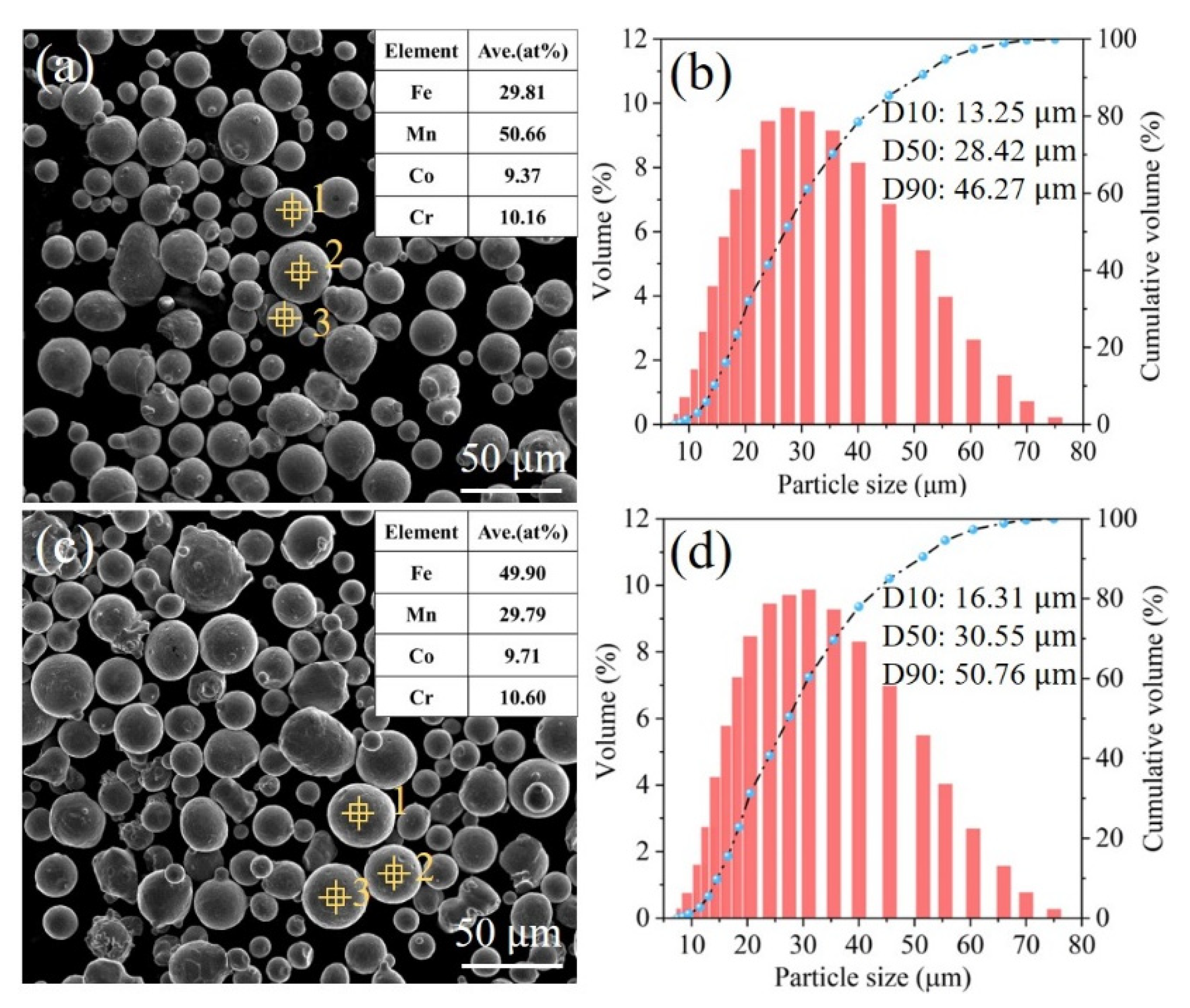
2.1. Materials
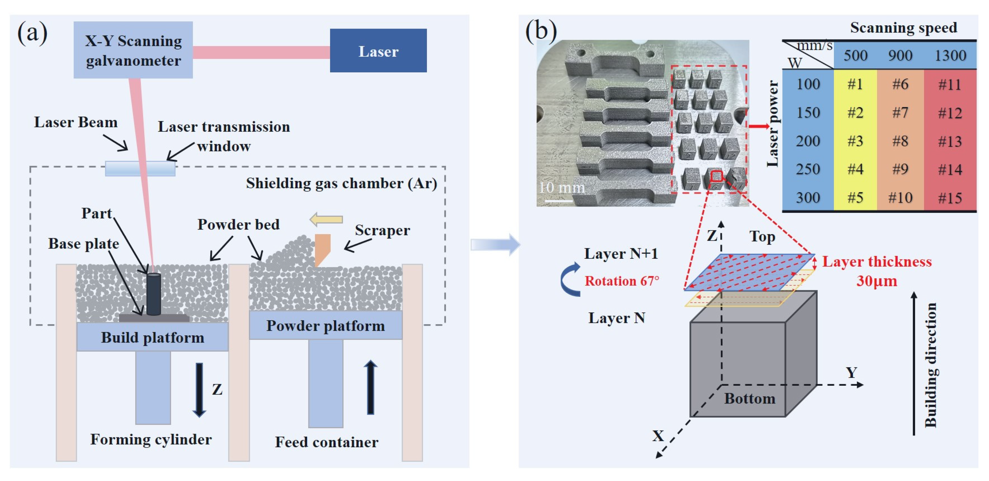
2.2. Sample Fabrication by LPBF
2.3. Characterizations
2.4. Mechanical Testing
3. Results and Discussion
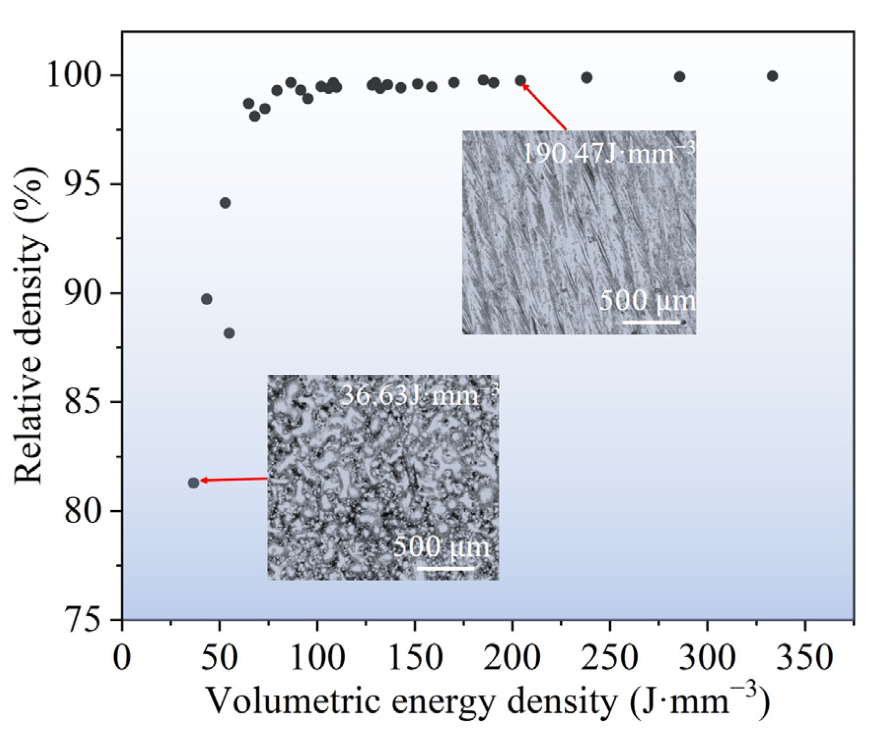
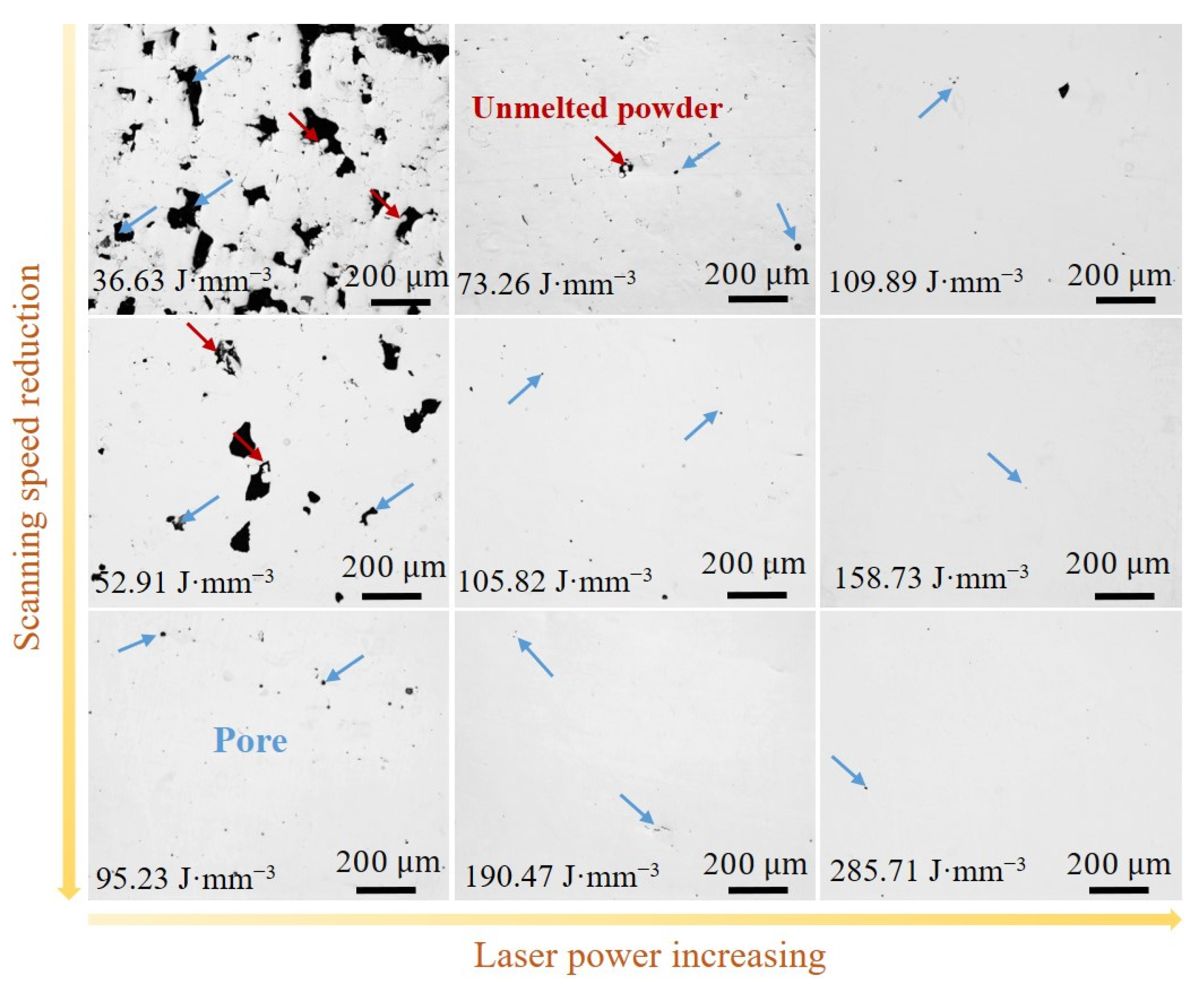
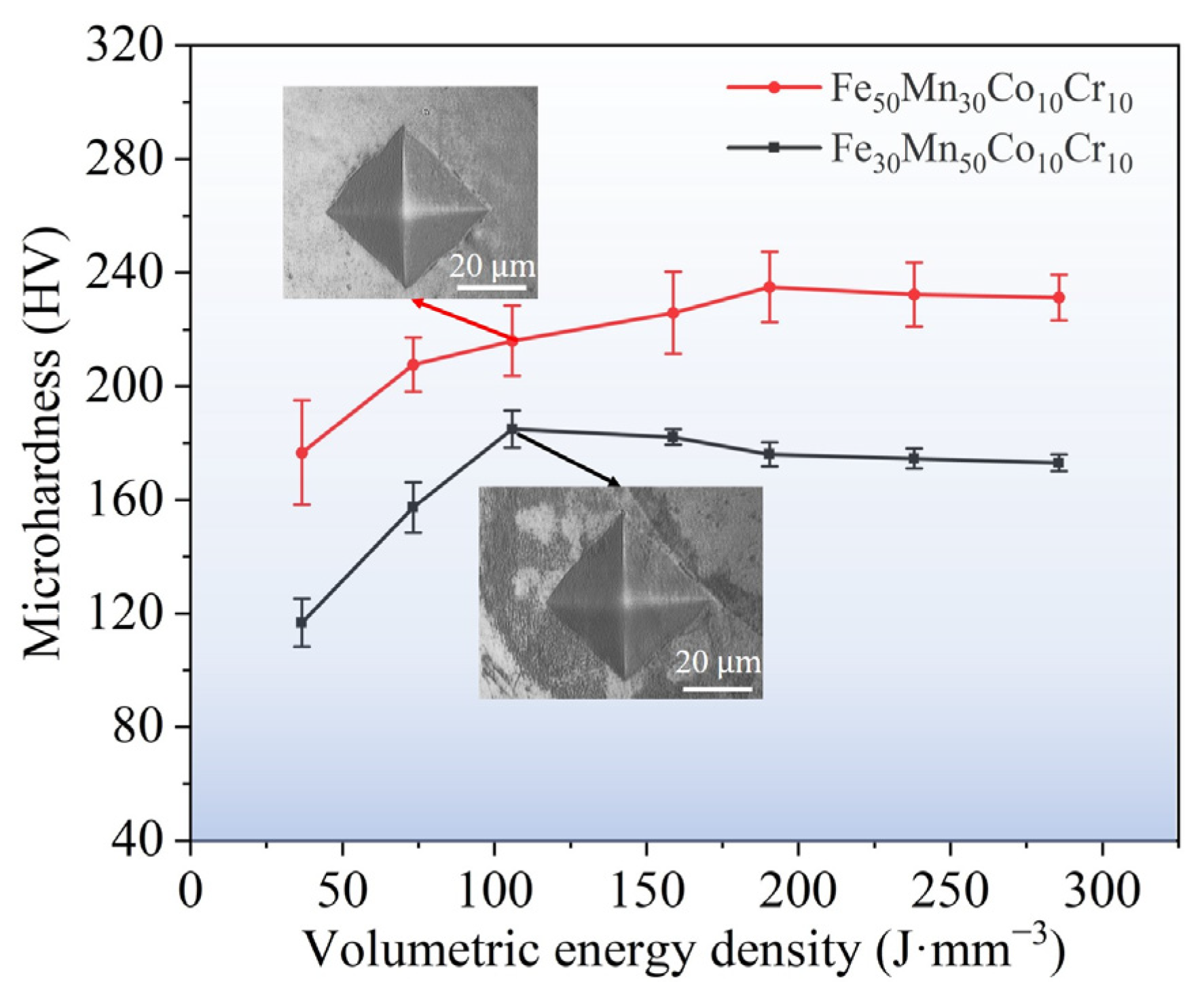
3.1. The Printability of LPBF-Printed Fe80−xMnxCo10Cr10 HEAs
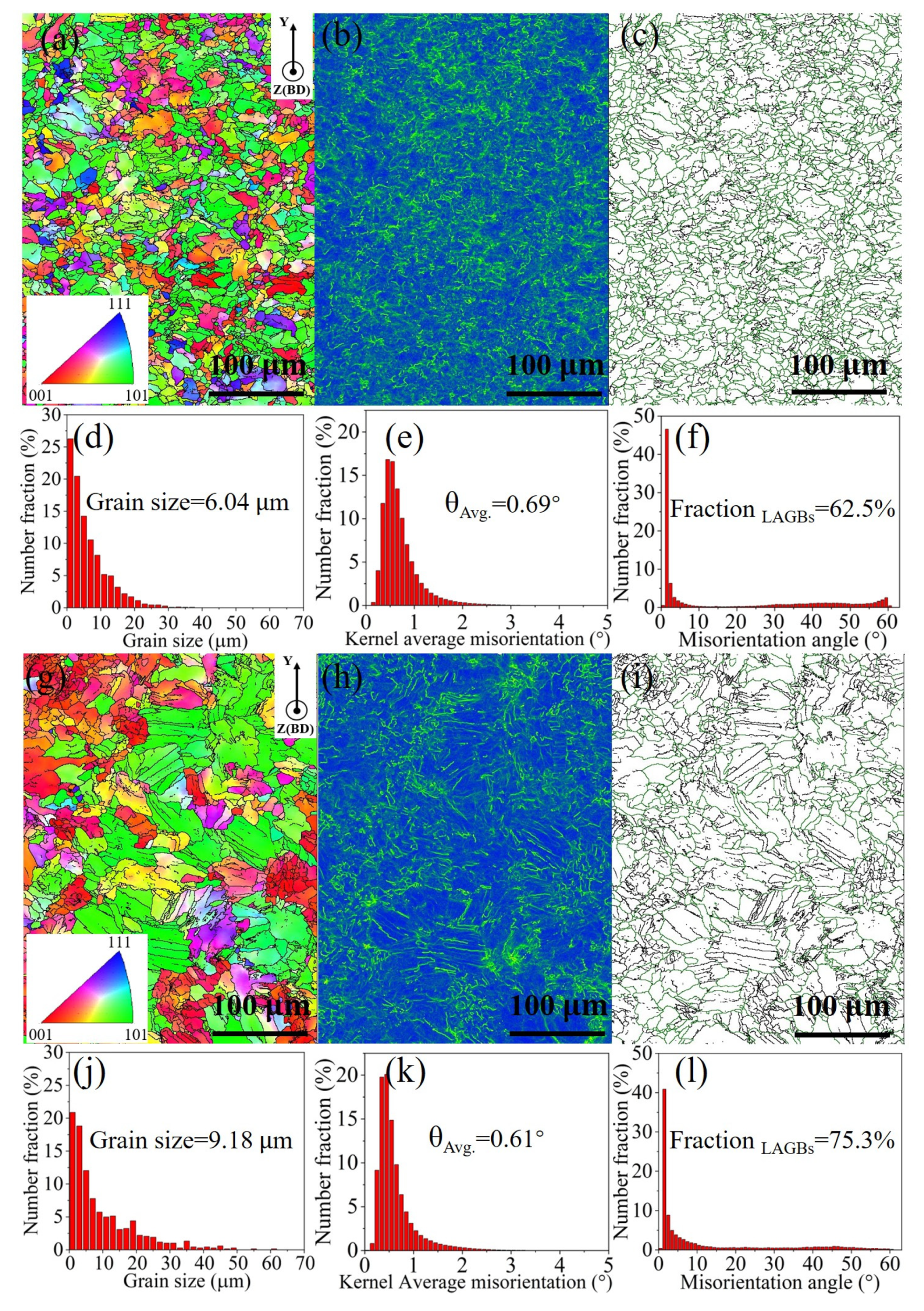
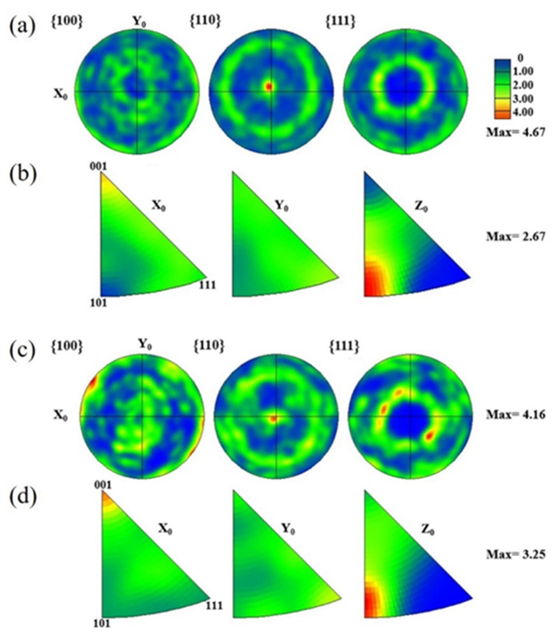
3.2. The Microstructure of LPBF-Printed Fe80−xMnxCo10Cr10 HEAs
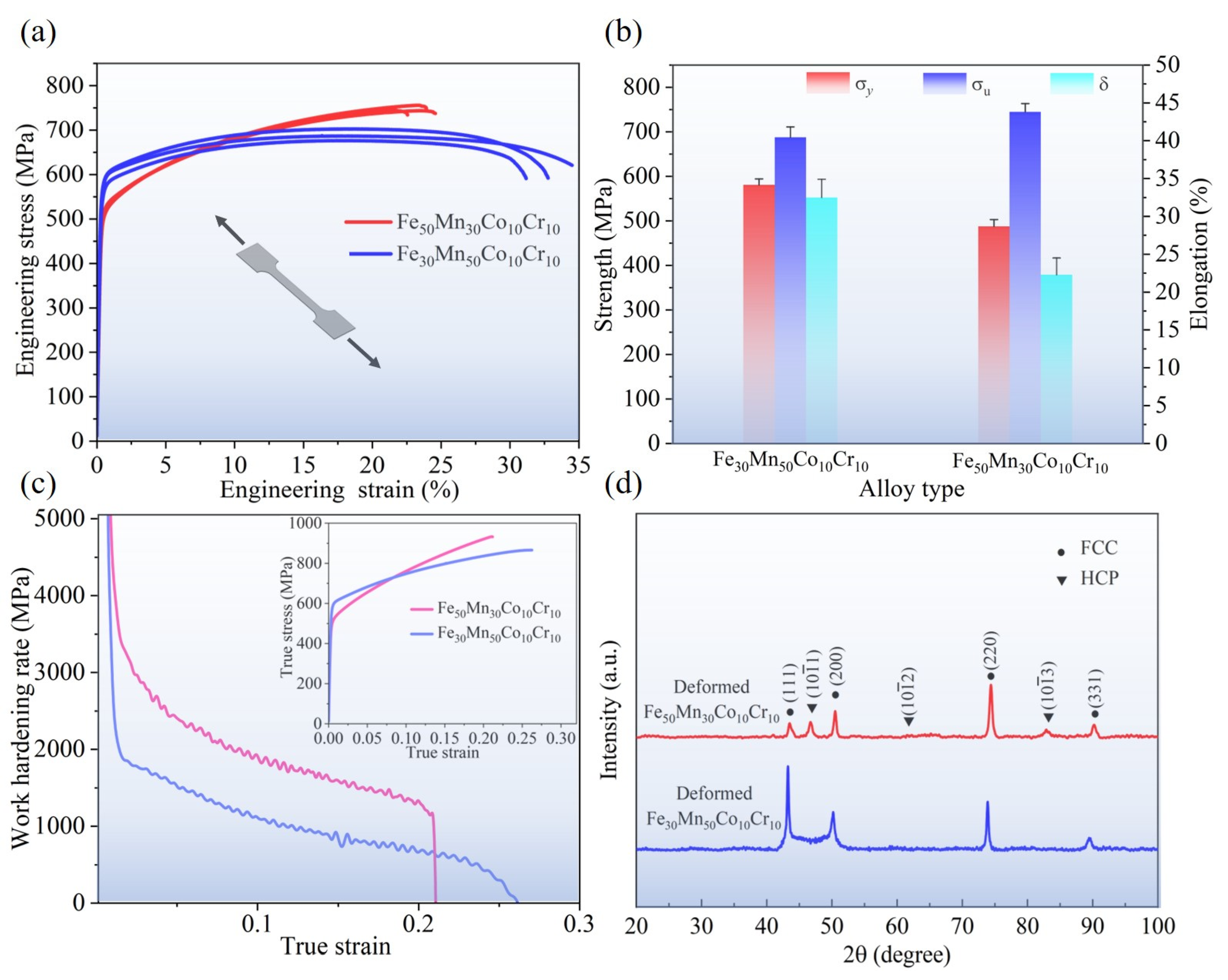
3.3. Mechanical Properties
4. Conclusions
Author Contributions
Funding
Data Availability Statement
Conflicts of Interest
References
- Shi, W.; Li, J.; Liu, Y.; Liu, S.; Lin, Y.; Han, Y. Experimental study on mechanism of influence of laser energy density on surface quality of Ti-6Al-4V alloy in selective laser melting. J. Cent. South Univ. 2022, 29, 3447–3462. [Google Scholar] [CrossRef]
- Ren, J.; Zhang, Y.; Zhao, D.; Chen, Y.; Guan, S.; Liu, Y.; Liu, L.; Peng, S.; Kong, F.; Poplawsky, J.D.; et al. Strong yet ductile nanolamellar high-entropy alloys by additive manufacturing. Nature 2022, 608, 62–68. [Google Scholar] [CrossRef]
- DebRoy, T.; Wei, H.L.; Zuback, J.S.; Mukherjee, T.; Elmer, J.W.; Milewski, J.O.; Beese, A.M.; Wilson-Heid, A.D.; De, A.; Zhang, W. Additive manufacturing of metallic components–process, structure and properties. Prog. Mater. Sci. 2018, 92, 112–224. [Google Scholar] [CrossRef]
- Li, R.; Niu, P.; Yuan, T.; Li, Z. Displacive transformation as pathway to prevent micro-cracks induced by thermal stress in additively manufactured strong and ductile high-entropy alloys. Trans. Nonferrous Met. Soc. China 2021, 31, 1059–1073. [Google Scholar] [CrossRef]
- Kartikeya Sarma, I.; Selvaraj, N.; Kumar, A. Parametric investigation and characterization of 17-4 PH stainless steel parts fabricated by selective laser melting. J. Cent. South Univ. 2023, 30, 855–870. [Google Scholar] [CrossRef]
- Han, C.; Fang, Q.; Shi, Y.; Tor, S.B.; Chua, C.K.; Zhou, K. Recent advances on high-entropy alloys for 3D printing. Adv. Mater. 2020, 32, 1903855. [Google Scholar] [CrossRef]
- Yeh, J.W.; Chen, S.K.; Lin, S.J.; Gan, J.Y.; Chin, T.S.; Shun, T.T.; Tsau, C.H.; Chang, S.Y. Nanostructured high-entropy alloys with multiple principal elements: Novel alloy design concepts and outcomes. Adv. Eng. Mater. 2004, 6, 299–303. [Google Scholar] [CrossRef]
- Li, Z.; Zhao, S.; Ritchie, R.O.; Meyers, M.A. Mechanical properties of high-entropy alloys with emphasis on face-centered cubic alloys. Prog. Mater. Sci. 2019, 102, 296–345. [Google Scholar] [CrossRef]
- Otto, F.; Dlouhý, A.; Somsen, C.; Bei, H.; Eggeler, G.; George, E.P. The influences of temperature and microstructure on the tensile properties of a CoCrFeMnNi high-entropy alloy. Acta Mater. 2013, 61, 5743–5755. [Google Scholar] [CrossRef]
- Gali, A.; George, E.P. Tensile properties of high- and medium-entropy alloys. Intermetallics 2013, 39, 74–78. [Google Scholar] [CrossRef]
- Salishchev, G.A.; Tikhonovsky, M.A.; Shaysultanov, D.G.; Stepanov, N.D.; Kuznetsov, A.V.; Kolodiy, I.V.; Tortika, A.S.; Senkov, O.N. Effect of Mn and V on structure and mechanical properties of high-entropy alloys based on CoCrFeNi system. J. Alloys Compd. 2014, 591, 11–21. [Google Scholar] [CrossRef]
- Chen, J.; Yao, Z.; Wang, X.; Lu, Y.; Wang, X.; Liu, Y.; Fan, X. Effect of C content on microstructure and tensile properties of as-cast CoCrFeMnNi high entropy alloy. Mater. Chem. Phys. 2018, 210, 136–145. [Google Scholar] [CrossRef]
- Laplanche, G.; Kostka, A.; Horst, O.M.; Eggeler, G.; George, E.P. Microstructure evolution and critical stress for twinning in the CrMnFeCoNi high-entropy alloy. Acta Mater. 2016, 118, 152–163. [Google Scholar] [CrossRef]
- Yao, M.J.; Pradeep, K.G.; Tasan, C.C.; Raabe, D. A novel, single phase, non-equiatomic FeMnNiCoCr high-entropy alloy with exceptional phase stability and tensile ductility. Scr. Mater. 2014, 72, 5–8. [Google Scholar] [CrossRef]
- Kim, J.; Kim, J. Grain size-dependent phase-specific deformation mechanisms of the Fe50Mn30Co10Cr10 high entropy alloy. Mater. Sci. Eng. A 2022, 854, 143867. [Google Scholar] [CrossRef]
- Li, Z.; Pradeep, K.G.; Deng, Y.; Raabe, D.; Tasan, C.C. Metastable high-entropy dual-phase alloys overcome the strength–ductility trade-off. Nature 2016, 534, 227–230. [Google Scholar] [CrossRef]
- He, Z.F.; Jia, N.; Wang, H.W.; Liu, Y.; Li, D.Y.; Shen, Y.F. The effect of strain rate on mechanical properties and microstructure of a metastable FeMnCoCr high entropy alloy. Mater. Sci. Eng. A 2020, 776, 138982. [Google Scholar] [CrossRef]
- Wang, H.; He, Z.; Jia, N. Microstructure and mechanical properties of a FeMnCoCr high-entropy alloy with heterogeneous structure. Acta Met. Sin. 2020, 57, 632–640. [Google Scholar]
- Guan, S.; Wan, D.; Solberg, K.; Berto, F.; Welo, T.; Yue, T.M.; Chan, K.C. Additive manufacturing of fine-grained and dislocation-populated CrMnFeCoNi high entropy alloy by laser engineered net shaping. Mater. Sci. Eng. A 2019, 761, 138056. [Google Scholar] [CrossRef]
- Guo, C.; Wei, S.; Wu, Z.; Wang, P.; Zhang, B.; Ramamurty, U.; Qu, X. Effect of dual phase structure induced by chemical segregation on hot tearing reduction in additive manufacturing. Mater. Des. 2023, 228, 111847. [Google Scholar] [CrossRef]
- Li, R.; Niu, P.; Yuan, T.; Cao, P.; Chen, C.; Zhou, K. Selective laser melting of an equiatomic CoCrFeMnNi high-entropy alloy: Processability, non-equilibrium microstructure and mechanical property. J. Alloys Compd. 2018, 746, 125–134. [Google Scholar] [CrossRef]
- Huang, H.; Wu, Y.; He, J.; Wang, H.; Liu, X.; An, K.; Wu, W.; Lu, Z. Phase-transformation ductilization of brittle high-entropy alloys via metastability engineering. Adv. Mater. 2017, 29, 1701678. [Google Scholar] [CrossRef] [PubMed]
- Wang, X.; De Vecchis, R.R.; Li, C.; Zhang, H.; Hu, X.; Sridar, S.; Wang, Y.; Chen, W.; Xiong, W. Design metastability in high-entropy alloys by tailoring unstable fault energies. Sci. Adv. 2022, 8, o7333. [Google Scholar] [CrossRef] [PubMed]
- Antolovich, S.D.; Singh, B. On the toughness increment associated with the austenite to martensite phase transformation in TRIP steels. Metall. Mater. Trans. B 1971, 2, 2135–2141. [Google Scholar] [CrossRef]
- Agrawal, P.; Haridas, R.S.; Thapliyal, S.; Yadav, S.; Mishra, R.S.; McWilliams, B.A.; Cho, K.C. Metastable high entropy alloys: An excellent defect tolerant material for additive manufacturing. Mater. Sci. Eng. A 2021, 826, 142005. [Google Scholar] [CrossRef]
- Wang, X.; Liu, C.; Sun, B.; Ponge, D.; Jiang, C.; Raabe, D. The dual role of martensitic transformation in fatigue crack growth. Proc. Natl. Acad. Sci. USA 2022, 119, e2110139119. [Google Scholar] [CrossRef] [PubMed]
- Jacques, P.; Furnemont, Q.; Pardoen, T.; Delannay, F. On the role of martensitic transformation on damage and cracking resistance in TRIP-assisted multiphase steels. Acta Mater. 2001, 49, 139–152. [Google Scholar] [CrossRef]
- Lacroix, G.; Pardoen, T.; Jacques, P.J. The fracture toughness of TRIP-assisted multiphase steels. Acta Mater. 2008, 56, 3900–3913. [Google Scholar] [CrossRef]
- Wei, S.; Kim, J.; Tasan, C.C. Boundary micro-cracking in metastable Fe45Mn35Co10Cr10 high-entropy alloys. Acta Mater. 2019, 168, 76–86. [Google Scholar] [CrossRef]
- Hu, C.; Huang, C.P.; Liu, Y.X.; Perlade, A.; Zhu, K.Y.; Huang, M.X. The dual role of TRIP effect on ductility and toughness of a medium Mn steel. Acta Mater. 2023, 245, 118629. [Google Scholar] [CrossRef]
- Li, Z.; Li, H.; Yin, J.; Li, Y.; Nie, Z.; Li, X.; You, D.; Guan, K.; Duan, W.; Cao, L.; et al. A review of spatter in laser powder bed fusion additive manufacturing: In situ detection, generation, effects, and countermeasures. Micromachines 2022, 13, 1366. [Google Scholar] [CrossRef] [PubMed]
- Guo, L.; Liu, H.; Wang, H.; Wei, Q.; Xiao, Y.; Tang, Z.; Wu, Y.; Wang, H. Identifying the keyhole stability and pore formation mechanisms in laser powder bed fusion additive manufacturing. J. Mater. Process. Technol. 2023, 321, 118153. [Google Scholar] [CrossRef]
- Wang, L.; Zhang, Y.; Chia, H.Y.; Yan, W. Mechanism of keyhole pore formation in metal additive manufacturing. NPJ Comput. Mater. 2022, 8, 22. [Google Scholar] [CrossRef]
- Michi, R.A.; Plotkowski, A.; Shyam, A.; Dehoff, R.R.; Babu, S.S. Towards high-temperature applications of aluminium alloys enabled by additive manufacturing. Int. Mater. Rev. 2022, 67, 298–345. [Google Scholar] [CrossRef]
- Hall, E.O. The deformation and ageing of mild steel: III discussion of results. Proc. Phys. Society. Sect. B 1951, 64, 747. [Google Scholar] [CrossRef]
- Tan, L.; Sridharan, K.; Allen, T.R. Effect of thermomechanical processing on grain boundary character distribution of a Ni-based superalloy. J. Nucl. Mater. 2007, 371, 171–175. [Google Scholar] [CrossRef]
- Zhou, K.; Han, C. Laser Powder Bed Fusion. Met. Powder-Based Addit. Manuf. 2023, 75–159. [Google Scholar] [CrossRef]
- Calcagnotto, M.; Ponge, D.; Demir, E.; Raabe, D. Orientation gradients and geometrically necessary dislocations in ultrafine grained dual-phase steels studied by 2D and 3D EBSD. Mater. Sci. Eng. A 2010, 527, 2738–2746. [Google Scholar] [CrossRef]
- Zhu, Z.G.; Nguyen, Q.B.; Ng, F.L.; An, X.H.; Liao, X.Z.; Liaw, P.K.; Nai, S.; Wei, J. Hierarchical microstructure and strengthening mechanisms of a CoCrFeNiMn high entropy alloy additively manufactured by selective laser melting. Scr. Mater. 2018, 154, 20–24. [Google Scholar] [CrossRef]
- Wang, B.; Sun, M.; Li, B.; Zhang, L.; Lu, B. Anisotropic response of CoCrFeMnNi high-entropy alloy fabricated by selective laser melting. Materials 2020, 13, 5687. [Google Scholar] [CrossRef]
- Chen, P.; Yang, C.; Li, S.; Attallah, M.M.; Yan, M. In-situ alloyed, oxide-dispersion-strengthened CoCrFeMnNi high entropy alloy fabricated via laser powder bed fusion. Mater. Des. 2020, 194, 108966. [Google Scholar] [CrossRef]
- Haase, C.; Tang, F.; Wilms, M.B.; Weisheit, A.; Hallstedt, B. Combining thermodynamic modeling and 3D printing of elemental powder blends for high-throughput investigation of high-entropy alloys–Towards rapid alloy screening and design. Mater. Sci. Eng. A 2017, 688, 180–189. [Google Scholar] [CrossRef]
- Xiang, S.; Luan, H.; Wu, J.; Yao, K.; Li, J.; Liu, X.; Tian, Y.; Mao, W.; Bai, H.; Le, G.; et al. Microstructures and mechanical properties of CrMnFeCoNi high entropy alloys fabricated using laser metal deposition technique. J. Alloys Compd. 2019, 773, 387–392. [Google Scholar] [CrossRef]
- Guo, L.; Gu, J.; Gan, B.; Ni, S.; Bi, Z.; Wang, Z.; Song, M. Effects of elemental segregation and scanning strategy on the mechanical properties and hot cracking of a selective laser melted FeCoCrNiMn-(N, Si) high entropy alloy. J. Alloys Compd. 2021, 865, 158892. [Google Scholar] [CrossRef]
- Hou, Y.; Liu, T.; He, D.; Li, Z.; Chen, L.; Su, H.; Fu, P.; Dai, P.; Huang, W. Sustaining strength-ductility synergy of SLM Fe50Mn30Co10Cr10 metastable high-entropy alloy by Si addition. Intermetallics 2022, 145, 107565. [Google Scholar] [CrossRef]
- Hou, Y.; Li, Z.; Chen, L.; Xiang, Z.; Dai, P.; Chen, J. SLM Fe50Mn30Co10Cr10 metastable high entropy alloy with Al-Ti addition: Synergizing strength and ductility. J. Alloys Compd. 2023, 941, 168830. [Google Scholar] [CrossRef]
- Niu, P.; Li, R.; Fan, Z.; Yuan, T.; Zhang, Z. Additive manufacturing of TRIP-assisted dual-phases Fe50Mn30Co10Cr10 high-entropy alloy: Microstructure evolution, mechanical properties and deformation mechanisms. Mater. Sci. Eng. A 2021, 814, 141264. [Google Scholar] [CrossRef]
- Zhu, Z.G.; An, X.H.; Lu, W.J.; Li, Z.M.; Ng, F.L.; Liao, X.Z.; Ramamurty, U.; Nai, S.M.L.; Wei, J. Selective laser melting enabling the hierarchically heterogeneous microstructure and excellent mechanical properties in an interstitial solute strengthened high entropy alloy. Mater. Res. Lett. 2019, 7, 453–459. [Google Scholar] [CrossRef]
- Thapliyal, S.; Agrawal, P.; Agrawal, P.; Nene, S.S.; Mishra, R.S.; McWilliams, B.A.; Cho, K.C. Segregation engineering of grain boundaries of a metastable Fe-Mn-Co-Cr-Si high entropy alloy with laser-powder bed fusion additive manufacturing. Acta Mater. 2021, 219, 117271. [Google Scholar] [CrossRef]
- Agrawal, P.; Thapliyal, S.; Nene, S.S.; Mishra, R.S.; McWilliams, B.A.; Cho, K.C. Excellent strength-ductility synergy in metastable high entropy alloy by laser powder bed additive manufacturing. Addit. Manuf. 2020, 32, 101098. [Google Scholar] [CrossRef]
- Kim, J.; Kim, J.H.; Park, H.; Kim, J.; Yang, G.; Kim, R.; Song, T.; Suh, D.; Kim, J. Temperature-dependent universal dislocation structures and transition of plasticity enhancing mechanisms of the Fe40Mn40Co10Cr10 high entropy alloy. Int. J. Plast. 2022, 148, 103148. [Google Scholar] [CrossRef]
- He, Z.F.; Jia, N.; Ma, D.; Yan, H.; Li, Z.M.; Raabe, D. Joint contribution of transformation and twinning to the high strength-ductility combination of a FeMnCoCr high entropy alloy at cryogenic temperatures. Mater. Sci. Eng. A 2019, 759, 437–447. [Google Scholar] [CrossRef]
- You, D.; Yang, G.; Choa, Y.; Kim, J. Crack-resistant σ/FCC interfaces in the Fe40Mn40Co10Cr10 high entropy alloy with the dispersed σ-phase. Mater. Sci. Eng. A 2022, 831, 142039. [Google Scholar] [CrossRef]
- Deng, Y.; Tasan, C.C.; Pradeep, K.G.; Springer, H.; Kostka, A.; Raabe, D. Design of a twinning-induced plasticity high entropy alloy. Acta Mater. 2015, 94, 124–133. [Google Scholar] [CrossRef]
- Tasan, C.C.; Deng, Y.; Pradeep, K.G.; Yao, M.J.; Springer, H.; Raabe, D. Composition dependence of phase stability, deformation mechanisms, and mechanical properties of the CoCrFeMnNi high-entropy alloy system. Jom 2014, 66, 1993–2001. [Google Scholar] [CrossRef]
- Gao, H.; Huang, Y.; Nix, W.D.; Hutchinson, J.W. Mechanism-based strain gradient plasticity—I. Theory. J. Mech. Phys. Solids 1999, 47, 1239–1263. [Google Scholar] [CrossRef]
- Fang, Q.; Chen, Y.; Li, J.; Jiang, C.; Liu, B.; Liu, Y.; Liaw, P.K. Probing the phase transformation and dislocation evolution in dual-phase high-entropy alloys. Int. J. Plast. 2019, 114, 161–173. [Google Scholar] [CrossRef]
- Yang, K.; Li, Y.; Hong, Z.; Du, S.; Ma, T.; Liu, S.; Jin, X. The dominating role of austenite stability and martensite transformation mechanism on the toughness and ductile-to-brittle-transition temperature of a quenched and partitioned steel. Mater. Sci. Eng. A 2021, 820, 141517. [Google Scholar] [CrossRef]
- Li, A.X.; Liu, X.S.; Li, R.; Yu, S.B.; Jiang, M.H.; Zhang, J.S.; Che, C.N.; Huang, D.; Yu, P.F.; Li, G. Double heterogeneous structures induced excellent strength-ductility synergy in Ni40Co30Cr20Al5Ti5 medium-entropy alloy. J. Mater. Sci. Technol. 2023, 181, 176–188. [Google Scholar] [CrossRef]
- Tian, C.; Ouyang, D.; Wang, P.; Zhang, L.; Cai, C.; Zhou, K.; Shi, Y. Strength-ductility synergy of an additively manufactured metastable high-entropy alloy achieved by transformation-induced plasticity strengthening. Int. J. Plast. 2024, 172, 103823. [Google Scholar] [CrossRef]


| HEA | σy/(MPa) | σu/(MPa) | δ/(%) |
|---|---|---|---|
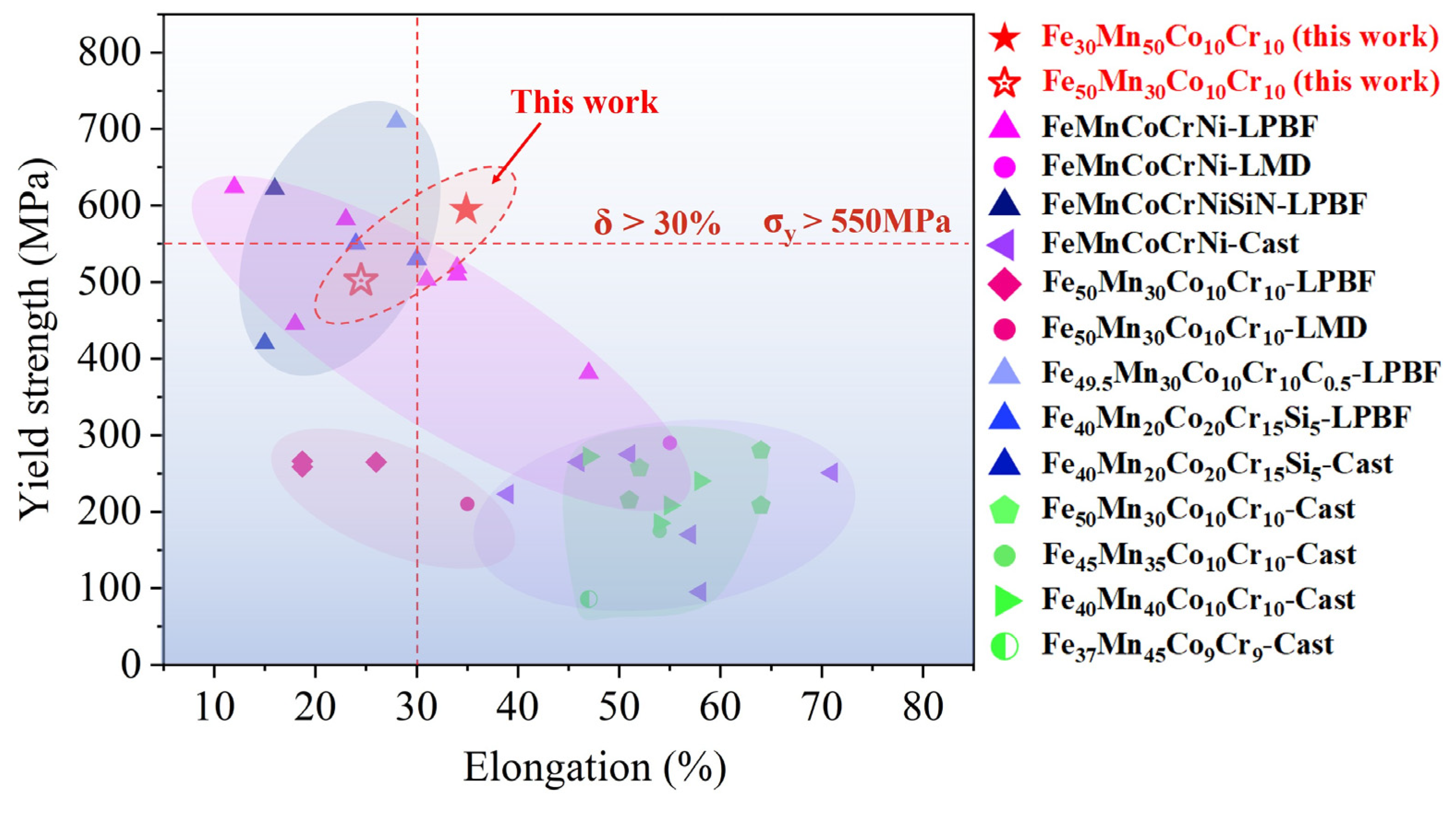
| Fe30Mn50Co10Cr10 | 580.65 ± 13.48 | 687.70 ± 23.25 | 32.5 ± 2.4 |
| Fe50Mn30Co10Cr10 | 487.60 ± 15.23 | 744.90 ± 18.47 | 22.3 ± 2.2 |
Disclaimer/Publisher’s Note: The statements, opinions and data contained in all publications are solely those of the individual author(s) and contributor(s) and not of MDPI and/or the editor(s). MDPI and/or the editor(s) disclaim responsibility for any injury to people or property resulting from any ideas, methods, instructions or products referred to in the content. |
© 2024 by the authors. Licensee MDPI, Basel, Switzerland. This article is an open access article distributed under the terms and conditions of the Creative Commons Attribution (CC BY) license (https://creativecommons.org/licenses/by/4.0/).
Share and Cite
Li, K.; Trofimov, V.; Han, C.; Hu, G.; Dong, Z.; Zou, Y.; Wang, Z.; Yan, F.; Fu, Z.; Yang, Y. The Printability, Microstructure, and Mechanical Properties of Fe80−xMnxCo10Cr10 High-Entropy Alloys Fabricated by Laser Powder Bed Fusion Additive Manufacturing. Micromachines 2024, 15, 123. https://doi.org/10.3390/mi15010123
Li K, Trofimov V, Han C, Hu G, Dong Z, Zou Y, Wang Z, Yan F, Fu Z, Yang Y. The Printability, Microstructure, and Mechanical Properties of Fe80−xMnxCo10Cr10 High-Entropy Alloys Fabricated by Laser Powder Bed Fusion Additive Manufacturing. Micromachines. 2024; 15(1):123. https://doi.org/10.3390/mi15010123
Chicago/Turabian StyleLi, Kai, Vyacheslav Trofimov, Changjun Han, Gaoling Hu, Zhi Dong, Yujin Zou, Zaichi Wang, Fubao Yan, Zhiqiang Fu, and Yongqiang Yang. 2024. "The Printability, Microstructure, and Mechanical Properties of Fe80−xMnxCo10Cr10 High-Entropy Alloys Fabricated by Laser Powder Bed Fusion Additive Manufacturing" Micromachines 15, no. 1: 123. https://doi.org/10.3390/mi15010123
APA StyleLi, K., Trofimov, V., Han, C., Hu, G., Dong, Z., Zou, Y., Wang, Z., Yan, F., Fu, Z., & Yang, Y. (2024). The Printability, Microstructure, and Mechanical Properties of Fe80−xMnxCo10Cr10 High-Entropy Alloys Fabricated by Laser Powder Bed Fusion Additive Manufacturing. Micromachines, 15(1), 123. https://doi.org/10.3390/mi15010123