


Experimental Study on Double-Joint Soft Actuator and Its Dexterous Hand


Abstract
:1. Introduction
2. Structural Design Fabrication
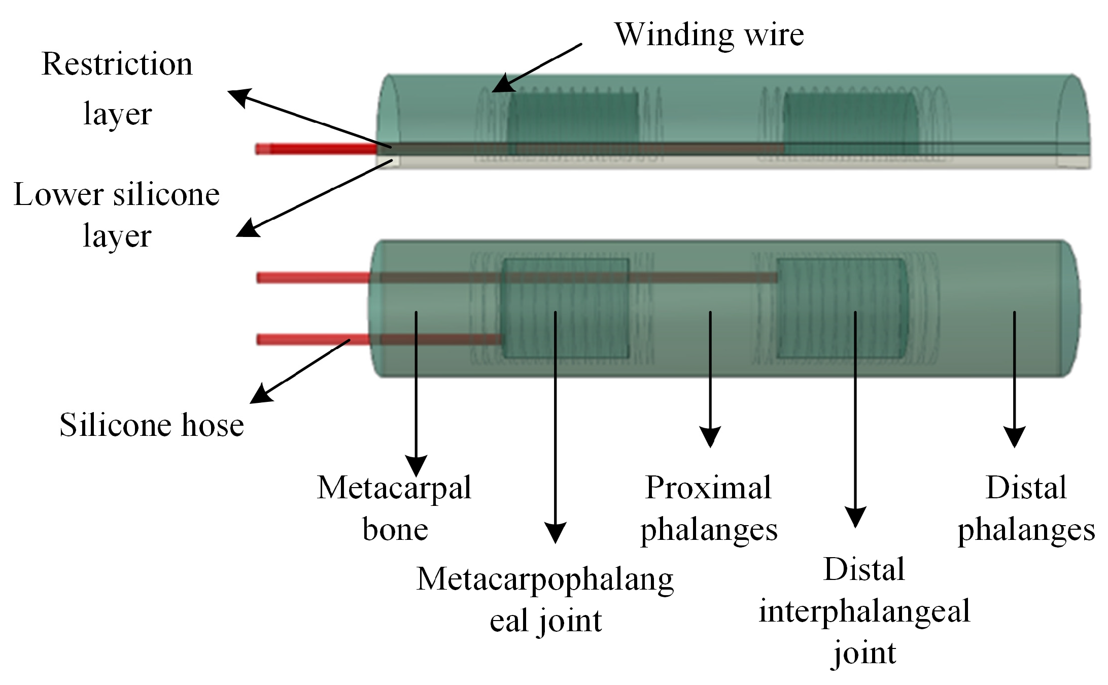
2.1. Soft Actuator Structure Design
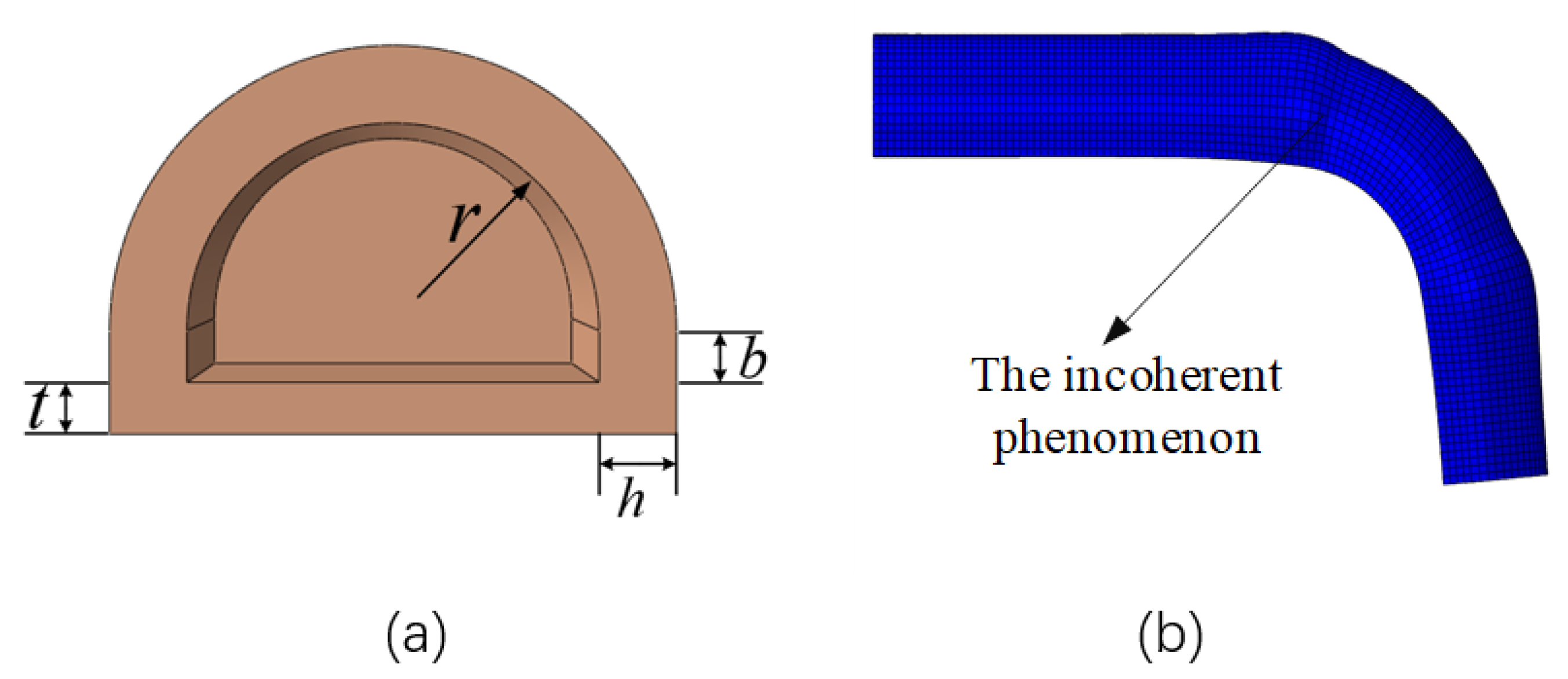
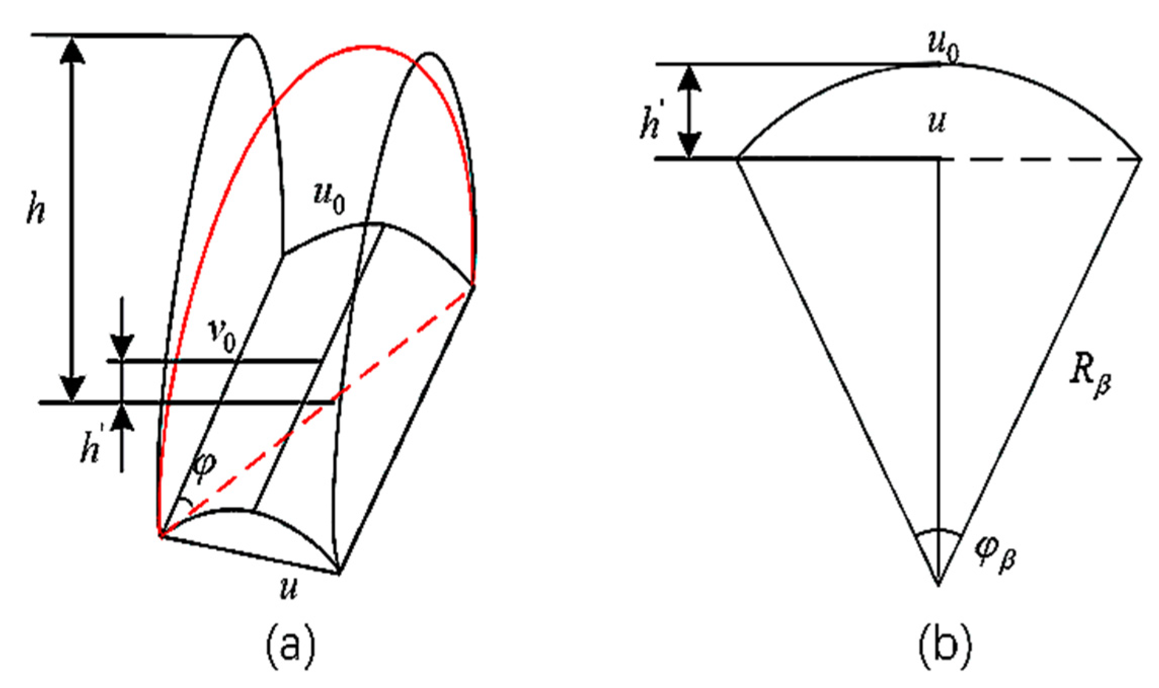
2.2. Soft Actuator Simulation Model and Parameter Determination
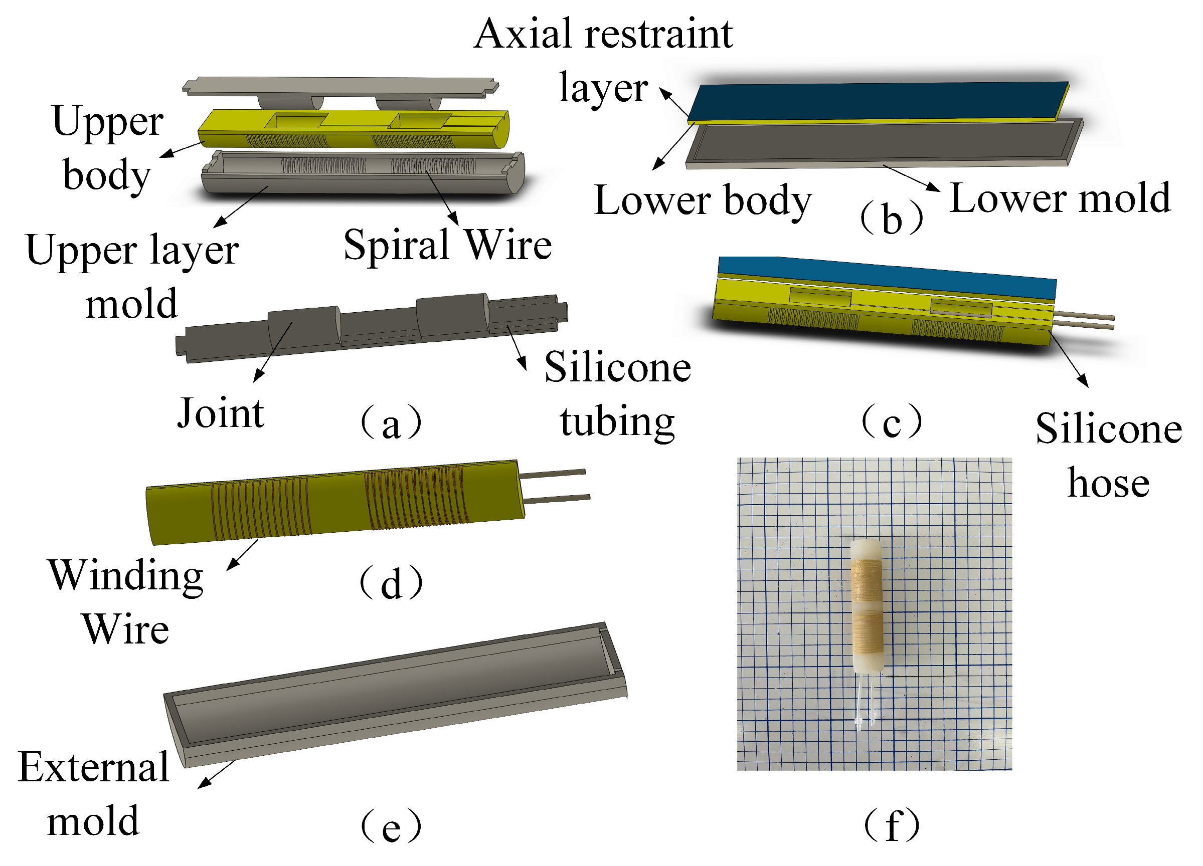
2.3. Preparation of Soft Actuator
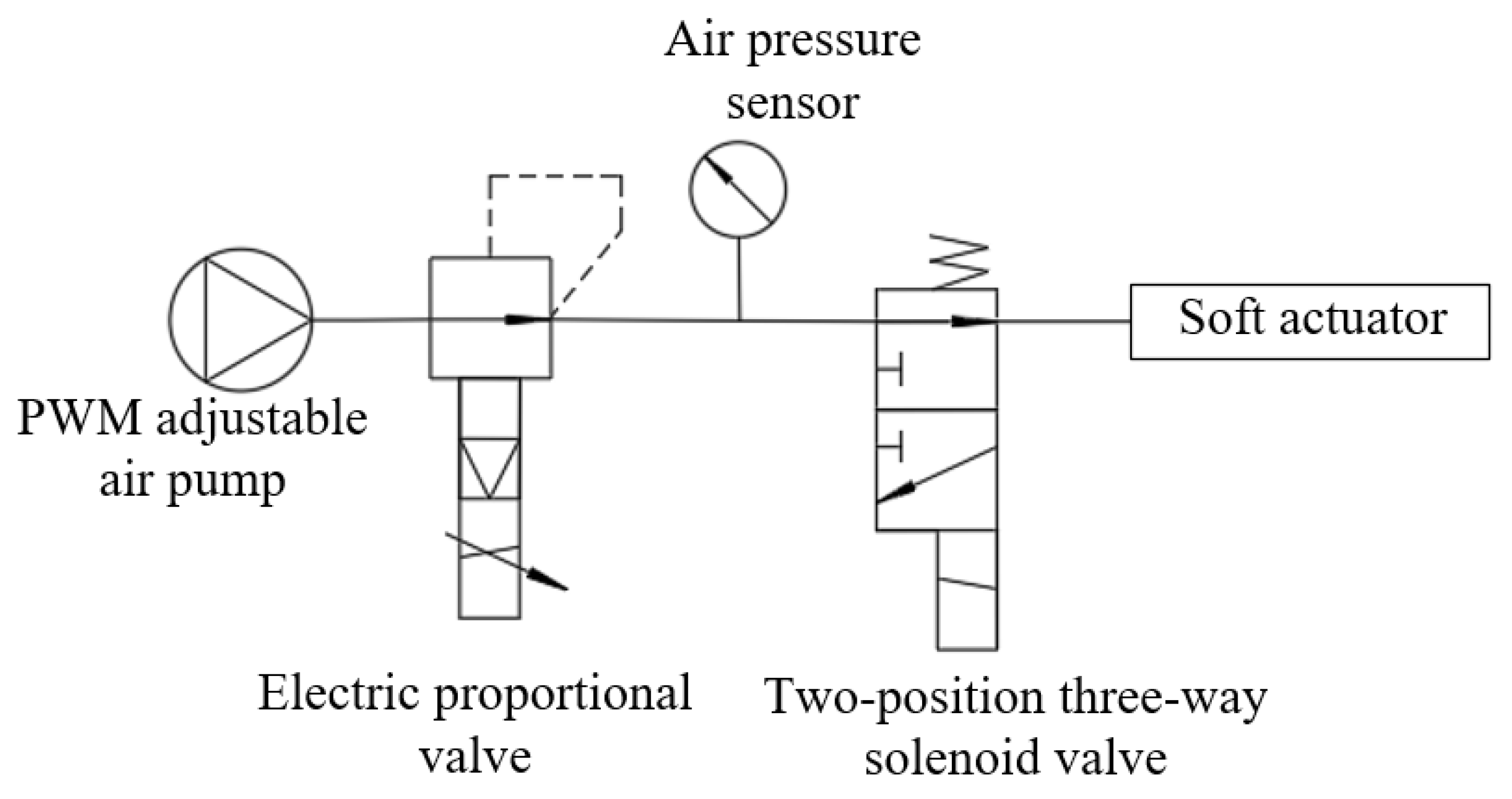
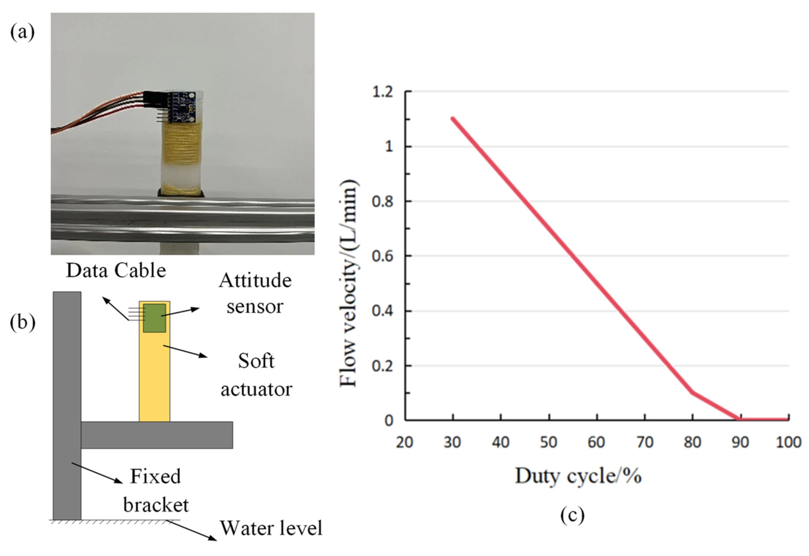
3. Experimental Platform and Performance Analysis
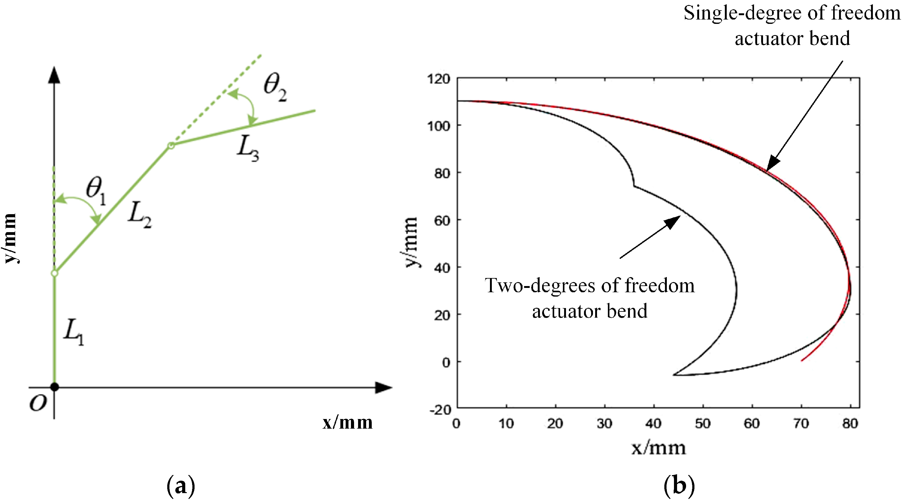
3.1. Soft Actuator Simulation Model and Parameter Determination
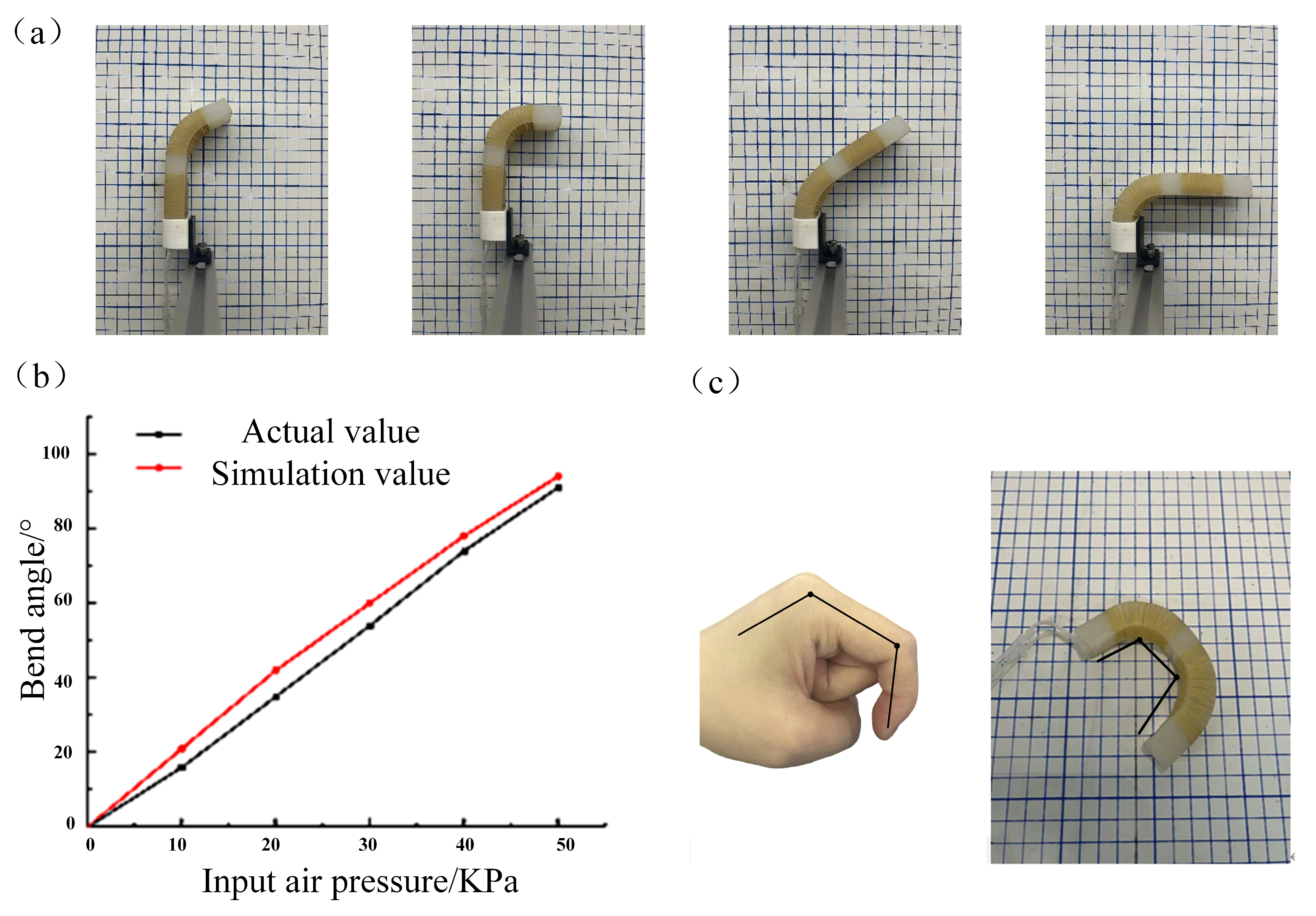
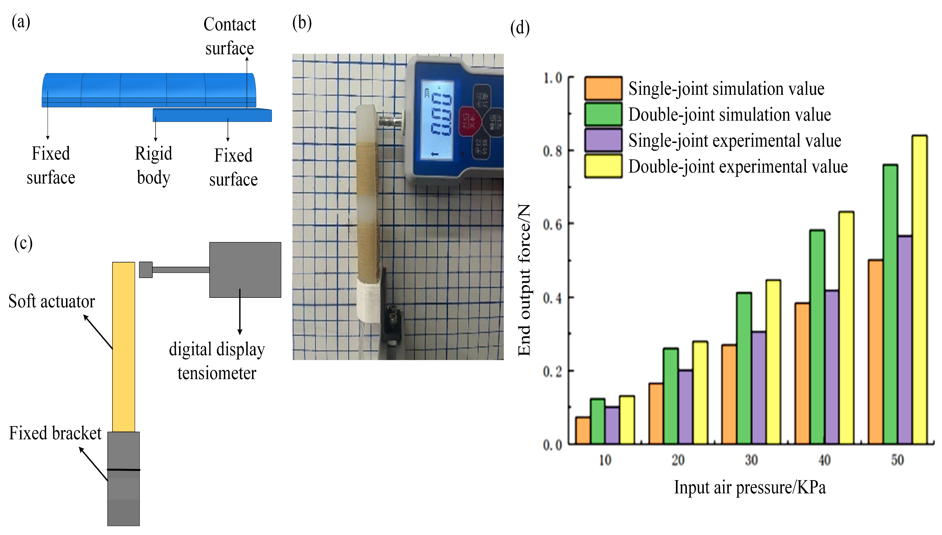
3.2. Soft Actuator Performance Analysis
4. Experimental Study of Dexterous Hand
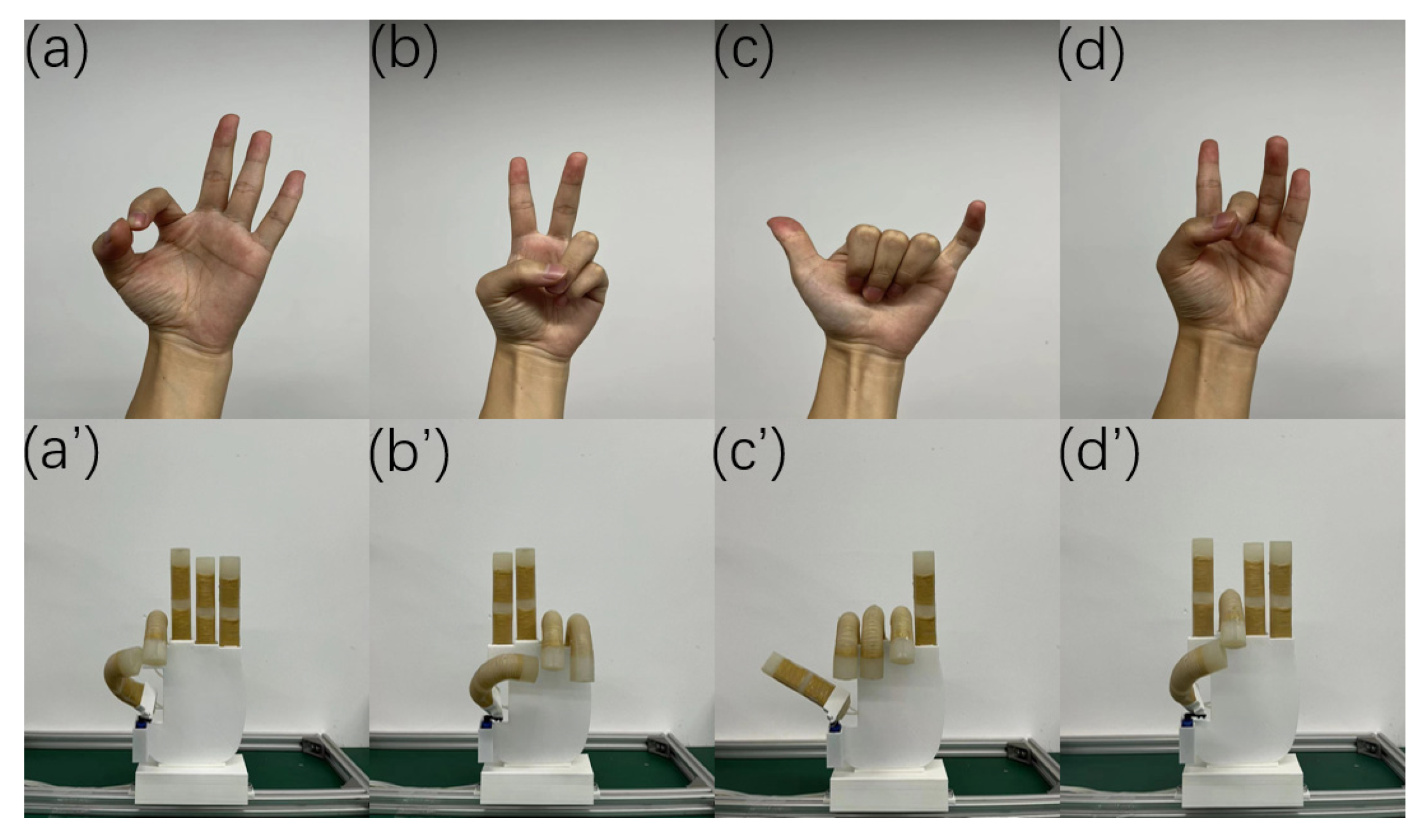
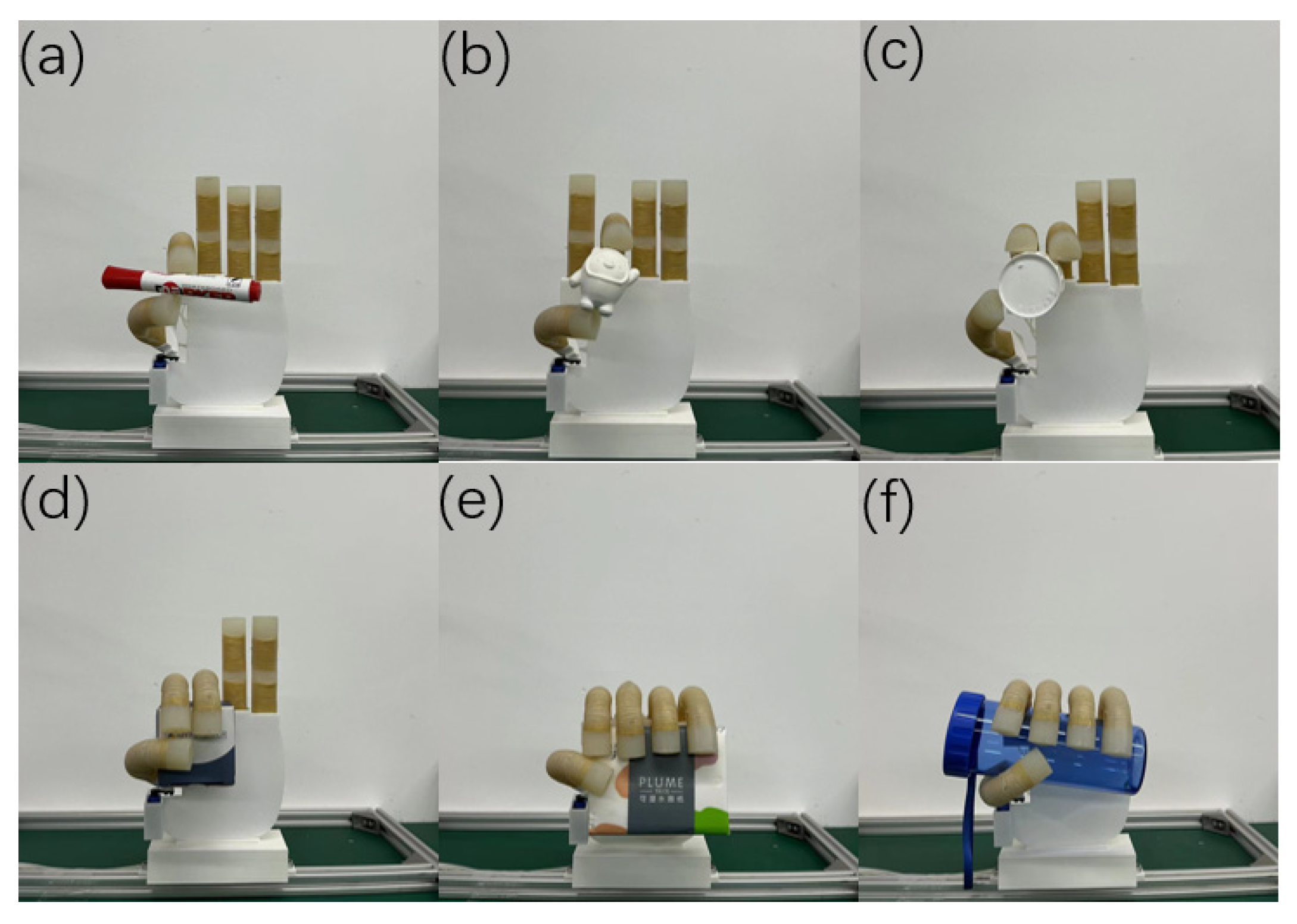
4.1. Dexterous Hand and General Grasping
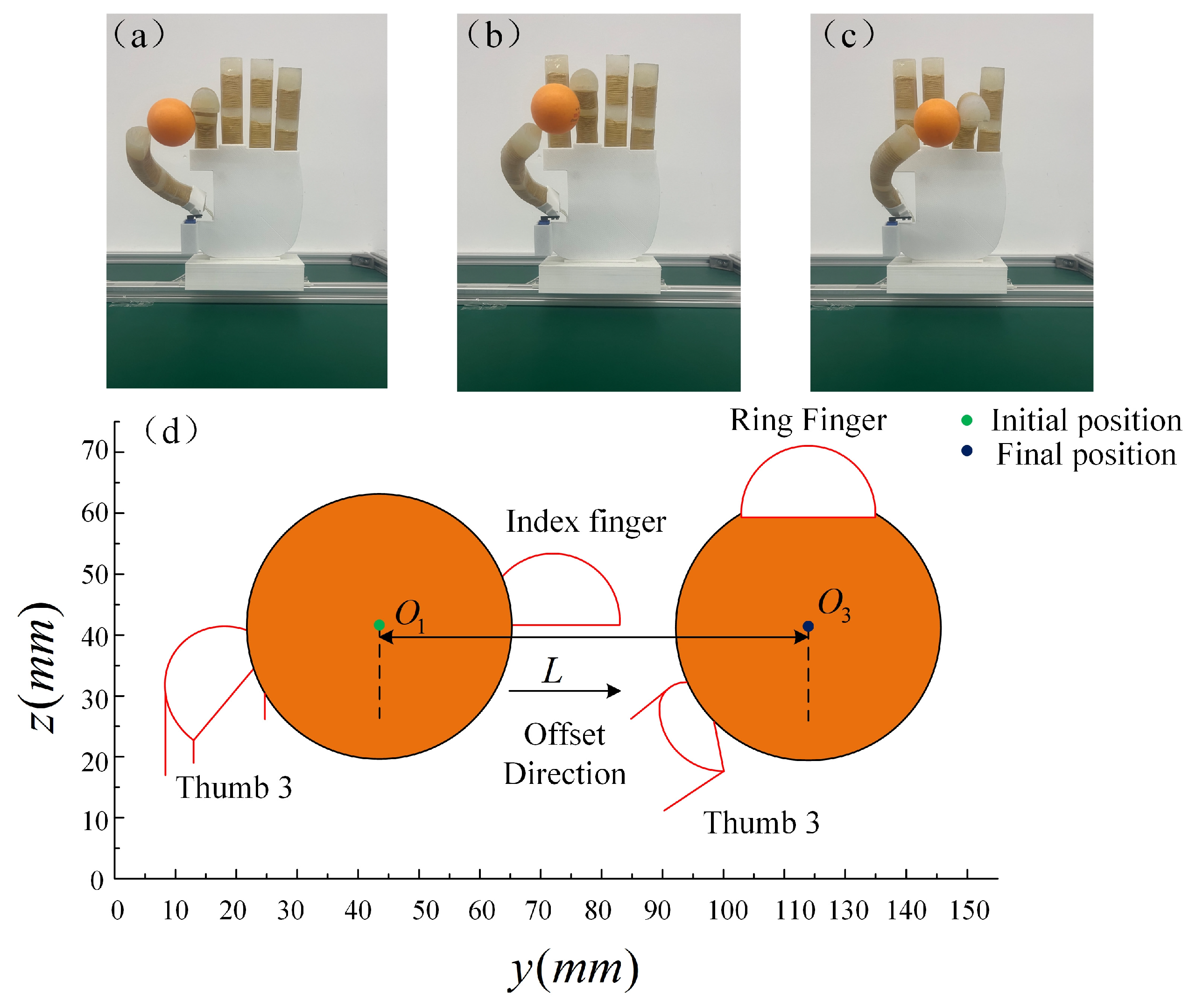
4.2. Length Grip
4.3. High Grip
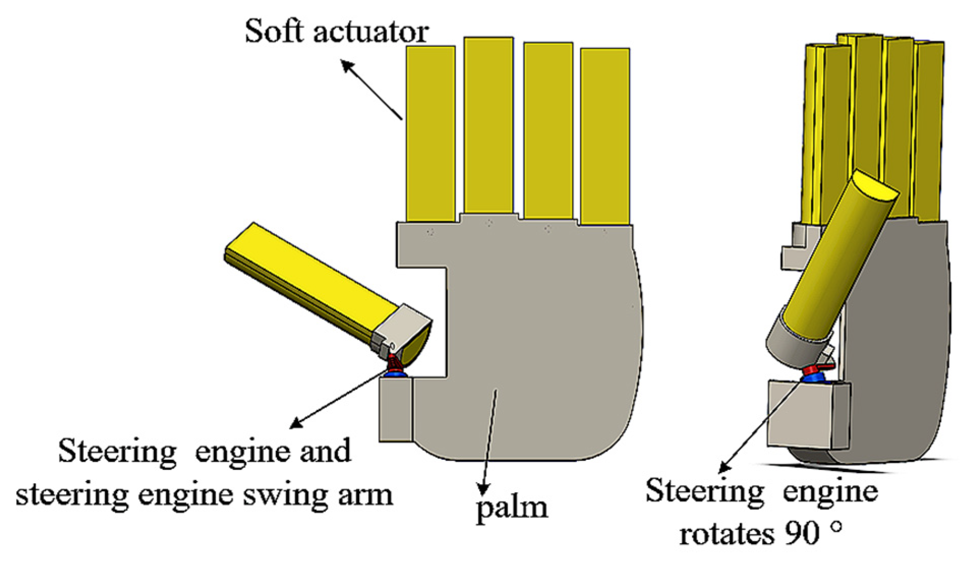
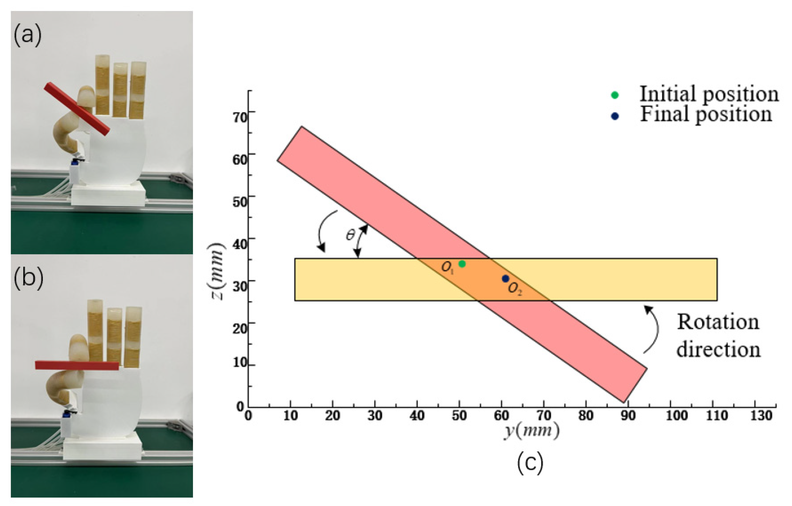
4.4. Angle Grabs
5. Conclusions
Author Contributions
Funding
Data Availability Statement
Conflicts of Interest
References
- Zhang, J.; Wang, T.; Hong, J.; Wang, M.Y. Review of soft-bodied manipulator. Am. J. Mech. Eng. 2017, 53, 19–28. [Google Scholar] [CrossRef]
- Cai, S.B.; Tao, Z.C.; Wan, W.W.; Yu, H.Y.; Bao, G.J. Multi-fingered Dexterous Hands: From Simplicity to Complexity and Simplifying Complex Applications. Chin. J. Mech. Eng. 2021, 57, 1–14. (In Chinese) [Google Scholar] [CrossRef]
- Li, X.; Fang, S.; Chen, S. The development status and its applications of soft manipulators. Manuf. Autom. 2019, 41, 85–92. (In Chinese) [Google Scholar] [CrossRef]
- Wu, S.; Ze, Q.; Dai, J.; Udipi, N.; Paulino, G.H.; Zhao, R. Stretchable origami robotic arm with omnidirectional bending and twisting. Proc. Natl. Acad. Sci. USA 2021, 118, e2110023118. [Google Scholar] [CrossRef] [PubMed]
- Yang, M.; Cooper, L.P.; Liu, N.; Wang, X.; Fok, M.P. Twining plant inspired pneumatic soft robotic spiral gripper with a fiber optic twisting sensor. Opt. Express 2020, 28, 35158–35167. [Google Scholar] [CrossRef] [PubMed]
- Kellaris, N.; Rothemund, P.; Zeng, Y.; Mitchell, S.K.; Smith, G.M.; Jayaram, K.; Keplinger, C. Spider-Inspired Electrohydraulic Actuators for Fast, Soft-Actuated Joints. Adv. Sci. 2021, 8, 2100916. [Google Scholar] [CrossRef]
- Li, T.; Li, G.; Liang, Y.; Cheng, T.; Dai, J.; Yang, X.; Liu, B.; Zeng, Z.; Huang, Z.; Luo, Y.; et al. Fast-moving soft electronic fish. Sci. Adv. 2017, 3, e1602045. [Google Scholar] [CrossRef]
- Zhang, J.; Wang, H.; Tang, J.; Guo, H.; Hong, J. Modeling and design of a soft pneumatic finger for hand rehabilitation. In Proceedings of the 2015 IEEE International Conference on Information and Automation, Lijiang, China, 8–10 August 2015; pp. 2460–2465. [Google Scholar] [CrossRef]
- Polygerinos, P.; Wang, Z.; Galloway, K.C.; Wood, R.J.; Walsh, C.J. Soft robotic glove for combined assistance and at-home rehabilitation. Rob. Auton. Syst. 2015, 73, 135–143. [Google Scholar] [CrossRef]
- Fang, G.; Chow, M.C.; Ho, J.D.; He, Z.; Wang, K.; Ng, T.C.; Tsoi, J.K.; Chan, P.L.; Chang, H.C.; Chan, D.T.; et al. Soft robotic manipulator for intraoperative MRI-guided transoral laser microsurgery. Sci. Robot. 2021, 6, eabg5575. [Google Scholar] [CrossRef]
- Galloway, K.C.; Becker, K.P.; Phillips, B.; Kirby, J.; Licht, S.; Tchernov, D.; Wood, R.J.; Gruber, D.F. Soft robotic grippers for biological sampling on deep reefs. Soft Robot. 2016, 3, 23–33. [Google Scholar] [CrossRef]
- Gong, Z.; Fang, X.; Chen, X.; Cheng, J.; Xie, Z.; Liu, J.; Chen, B.; Yang, H.; Kong, S.; Hao, Y.; et al. A soft manipulator for efficient delicate grasping in shallow water: Modeling, control, and real-world experiments. Int. J. Rob. Res. 2021, 40, 449–469. [Google Scholar] [CrossRef]
- Deimel, R.; Brock, O. A compliant hand based on a novel pneumatic actuator. In Proceedings of the 2013 IEEE International Conference on Robotics and Automation, Karlsruhe, Germany, 6–10 May 2013; pp. 2047–2053. [Google Scholar] [CrossRef]
- Puhlmann, S.; Harris, J.; Brock, O. RBO Hand 3: A platform for soft dexterous manipulation. IEEE Trans. Robot. 2022, 38, 3434–3449. [Google Scholar] [CrossRef]
- Zhou, J.; Chen, S.; Wang, Z. A soft-robotic gripper with enhanced object adaptation and grasping reliability. IEEE Robot. Autom. Lett. 2017, 2, 2287–2293. [Google Scholar] [CrossRef]
- Zhao, H.; O’brien, K.; Li, S.; Shepherd, R.F. Optoelectronically innervated soft prosthetic hand via stretchable optical waveguides. Sci. Robot. 2016, 1, eaai7529. [Google Scholar] [CrossRef]
- Li, Y.; Chen, Y.; Ren, T.; Hu, Y.; Liu, H.; Lin, S.; Yang, Y.; Li, Y.; Zhou, J. A dual-mode actuator for soft robotic hand. IEEE Robot. Autom. Lett. 2021, 6, 1144–1151. [Google Scholar] [CrossRef]
- Shiva, A.; Stilli, A.; Noh, Y.; Faragasso, A.; De Falco, I.; Gerboni, G.; Cianchetti, M.; Menciassi, A.; Althoefer, K.; Wurdemann, H.A. Tendon-based stiffening for a pneumatically actuated soft manipulator. IEEE Robot. Autom. Lett. 2016, 1, 632–637. [Google Scholar] [CrossRef]
- Zhang, B. Design and Analysis of a Robot Hand Based on the Combination of Continuous Flexible Finger and Rigid Tendon Drive Fingers. J. Phys. Conf. Ser. 2021, 1802, 022013. [Google Scholar] [CrossRef]
- Deimel, R.; Brock, O. A novel type of compliant and underactuated robotic hand for dexterous grasping. Int. J. Robot. Res. 2016, 35, 161–185. [Google Scholar] [CrossRef]
- Wei, S.; Wang, T.; Gu, G. Design of a Soft Pneumatic Robotic Gripper Based on Fiber-reinforced Actuator. J. Mech. Eng. 2017, 53, 29–38. (In Chinese) [Google Scholar] [CrossRef]
- Li, Y.; Chen, Y.; Yang, Y.; Wei, Y. Passive particle jamming and its stiffening of soft robotic grippers. IEEE Trans. Robot. 2017, 33, 446–455. [Google Scholar] [CrossRef]
- Tiziani, L.; Hart, A.; Cahoon, T.; Wu, F.; Asada, H.H.; Hammond, F.L. Empirical characterization of modular variable stiffness inflatable structures for supernumerary grasp-assist devices. Int. J. Rob. Res. 2017, 36, 1391–1413. [Google Scholar] [CrossRef]
- Yap, H.K.; Lim, J.H.; Nasrallah, F.; Goh, J.C.; Yeow, R.C. A soft exoskeleton for hand assistive and rehabilitation application using pneumatic actuators with variable stiffness. In Proceedings of the 2015 IEEE International Conference on Robotics and Automation (ICRA), Seattle, WA, USA, 26–30 May 2015; pp. 4967–4972. [Google Scholar] [CrossRef]
- Wang, J.; Fei, Y.; Pang, W. Design, modeling, and testing of a soft pneumatic glove with segmented pneunets bending actuators. IEEE ASME Trans. Mechatron. 2019, 24, 990–1001. [Google Scholar] [CrossRef]
- Zhang, Y.F.; Zhang, N.; Hingorani, H.; Ding, N.; Wang, D.; Yuan, C.; Zhang, B.; Gu, G.; Ge, Q. Fast-response, stiffness-tunable soft actuator by hybrid multimaterial 3D printing. Adv. Funct. Mater. 2019, 29, 1806698. [Google Scholar] [CrossRef]
- Polygerinos, P.; Wang, Z.; Overvelde, J.T.; Galloway, K.C.; Wood, R.J.; Bertoldi, K.; Walsh, C.J. Modeling of soft fiber-reinforced bending actuators. IEEE Trans. Robot. 2015, 31, 778–789. [Google Scholar] [CrossRef]
- Wang, Z.; Polygerinos, P.; Overvelde, J.T.; Galloway, K.C.; Bertoldi, K.; Walsh, C.J. Interaction forces of soft fiber reinforced bending actuators. IEEE ASME Trans. Mechatron. 2016, 22, 717–727. [Google Scholar] [CrossRef]
- Peer, A.; Einenkel, S.; Buss, M. Multi-fingered telemanipulation-mapping of a human hand to a three finger gripper. In Proceedings of the RO-MAN 2008-the 17th IEEE International Symposium on Robot and Human Interactive Communication, Munich, Germany, 1–3 August 2008; pp. 465–470. [Google Scholar] [CrossRef]


| Parameter of Dimension | The Numerical Value (Unit/mm) |
|---|---|
| Air chamber inner diameter, r | 8 |
| Rectangle width, b | 2 |
| Air chamber thickness, h | 3 |
| Bottom layer thickness, t | 3 |
| Joint length, l | 20 |
| Metacarpal | 20 |
| Finger bone 1 | 24 |
| Finger bone 2 | 26 |
| Serial Number | Designation | Quality/g | Size/mm |
|---|---|---|---|
| 1 | Marking pen | 13.9 | 17 × 17 × 135 |
| 2 | Bing Dwen Dwen | 35.2 | 52 × 32 × 50 |
| 3 | Bottle cap | 5.6 | 48 × 48 × 23 |
| 4 | Carton | 18.4 | 67 × 67 × 52 |
| 5 | Tissue | 68.3 | 114 × 88 × 56 |
| 6 | Cup | 123.5 | 64 × 64 × 160 |
Disclaimer/Publisher’s Note: The statements, opinions and data contained in all publications are solely those of the individual author(s) and contributor(s) and not of MDPI and/or the editor(s). MDPI and/or the editor(s) disclaim responsibility for any injury to people or property resulting from any ideas, methods, instructions or products referred to in the content. |
© 2023 by the authors. Licensee MDPI, Basel, Switzerland. This article is an open access article distributed under the terms and conditions of the Creative Commons Attribution (CC BY) license (https://creativecommons.org/licenses/by/4.0/).
Share and Cite
Chen, B.; Meng, Q.; Wang, J.; Lu, Z.; Cai, Y. Experimental Study on Double-Joint Soft Actuator and Its Dexterous Hand. Micromachines 2023, 14, 1966. https://doi.org/10.3390/mi14101966
Chen B, Meng Q, Wang J, Lu Z, Cai Y. Experimental Study on Double-Joint Soft Actuator and Its Dexterous Hand. Micromachines. 2023; 14(10):1966. https://doi.org/10.3390/mi14101966
Chicago/Turabian StyleChen, Bingxing, Qiuxu Meng, Junjie Wang, Zongxing Lu, and Yingjie Cai. 2023. "Experimental Study on Double-Joint Soft Actuator and Its Dexterous Hand" Micromachines 14, no. 10: 1966. https://doi.org/10.3390/mi14101966
APA StyleChen, B., Meng, Q., Wang, J., Lu, Z., & Cai, Y. (2023). Experimental Study on Double-Joint Soft Actuator and Its Dexterous Hand. Micromachines, 14(10), 1966. https://doi.org/10.3390/mi14101966