Article

High-Throughput White Blood Cell (Leukocyte) Enrichment from Whole Blood Using Hydrodynamic and Inertial Forces

1
School of Information and Communication Technology, Mongolian University of Science and Technology, Ulaanbaatar 14191, Mongolia
2
Department of Engineering and System Science, Frontier Research Center on Fundamental and Applied Sciences of Matters, National Tsing Hua University, Hsinchu 30013, Taiwan
3
Department of Life Science, National Tsing Hua University, Hsinchu 30013, Taiwan
4
Department of Biomechatronics Engineering, National Taiwan University, Taipei 10617, Taiwan
5
Department of Mechanical Engineering, Mongolian University of Science and Technology, Ulaanbaatar 14191, Mongolia
6
Department of Physics, Mongolian University of Science and Technology, Ulaanbaatar 14191, Mongolia
7
Research Center for Applied Sciences, Academia Sinica, Taipei 11529, Taiwan
*
Authors to whom correspondence should be addressed.
Micromachines 2020, 11(3), 275; https://doi.org/10.3390/mi11030275
Submission received: 8 January 2020 / Revised: 2 March 2020 / Accepted: 3 March 2020 / Published: 6 March 2020
(This article belongs to the Special Issue 10th Anniversary of Micromachines)

Abstract

:
A microfluidic chip, which can separate and enrich leukocytes from whole blood, is proposed. The chip has 10 switchback curve channels, which are connected by straight channels. The straight channels are designed to permit the inertial migration effect and to concentrate the blood cells, while the curve channels allow the Dean flow to further classify the blood cells based on the cell sizes. Hydrodynamic suction is also utilized to remove smaller blood cells (e.g., red blood cell (RBC)) in the curve channels for higher separation purity. By employing the inertial migration, Dean flow force, and hydrodynamic suction in a continuous flow system, our chip successfully separates large white blood cells (WBCs) from the whole blood with the processing rates as high as 1 × 10⁸ cells/sec at a high recovery rate at 93.2% and very few RBCs (~0.1%).

1. Introduction

Blood is an important compartment of the body; it circulates in the body and helps to keep the functions of life. Since blood may contain disease information, it is collected and stored for medical treatment when needed, with this information widely applied in disease detection and medical treatment [1]. As blood is composed of various types of cells, including erythrocytes (i.e., red blood cells (RBCs)), leukocytes (i.e., white blood cells (WBCs)), and thrombocytes (i.e., platelets (PLTs)), the capability to effectively separate blood cells can provide us with vital information for diagnosis of disease immune deficiency and genetic abnormalities [2,3,4].
In blood cell separation, size-based filtration using porous membranes has been a popular approach, although it may suffer from clogging, high flow stress and cell damage. On the other hand, microfluidics have been demonstrated to separate particles or cells, including pinched flow fractionation (PFF) [5,6,7,8,9], cross-flow filtration [10,11,12,13,14], microfluidic disk [15], laminar vortices [16,17,18], centrifugation/inertial focusing [19,20,21], and Dean flow [22,23,24,25]. Cell separation using microfluidics on a microchip provides advantages over conventional methods by scaling down the instrumentation size, simplifying the operation procedures for automation, as well as enabling the downstream integration for cellular isolation, analysis, and processing.
Recently, particle separation in microfluidics using inertial migration has received much attention because of its possibility in high throughput applications with simple designs [26,27,28,29,30,31]. The particles/cells flow in rectangular channels are focused near the cross-sectional corners of the channels due to the wall-crowding effect, whereby the wall repulsion forces push the particle away from the wall while the shear-gradient force draws the particle towards the wall. Hence, the balance between these two oppositely directed forces induce an equilibrium force at certain equilibrium positions [32].
Although the inertial migration technique permits high-throughput separation, higher separation efficiency is still desirable when it applies to separate biological cells (e.g., blood cells or rare cells) that usually have a large variety of sizes, shapes and rigidities for clinical applications. Herein, we propose to enhance the separation purity and efficiency of the inertial migration by adding (1) curve channels for Dean flow, (2) trench structures to induce additional secondary flows, as well as (3) hydrodynamic suction to improve the separation purity. Our microchip is designed to possess the advantage of the inertial migration with Dean flow and hydrodynamic suction; it has been created and successfully shows the RBC separation from whole blood with the WBC enrichment in a continuous flow system.

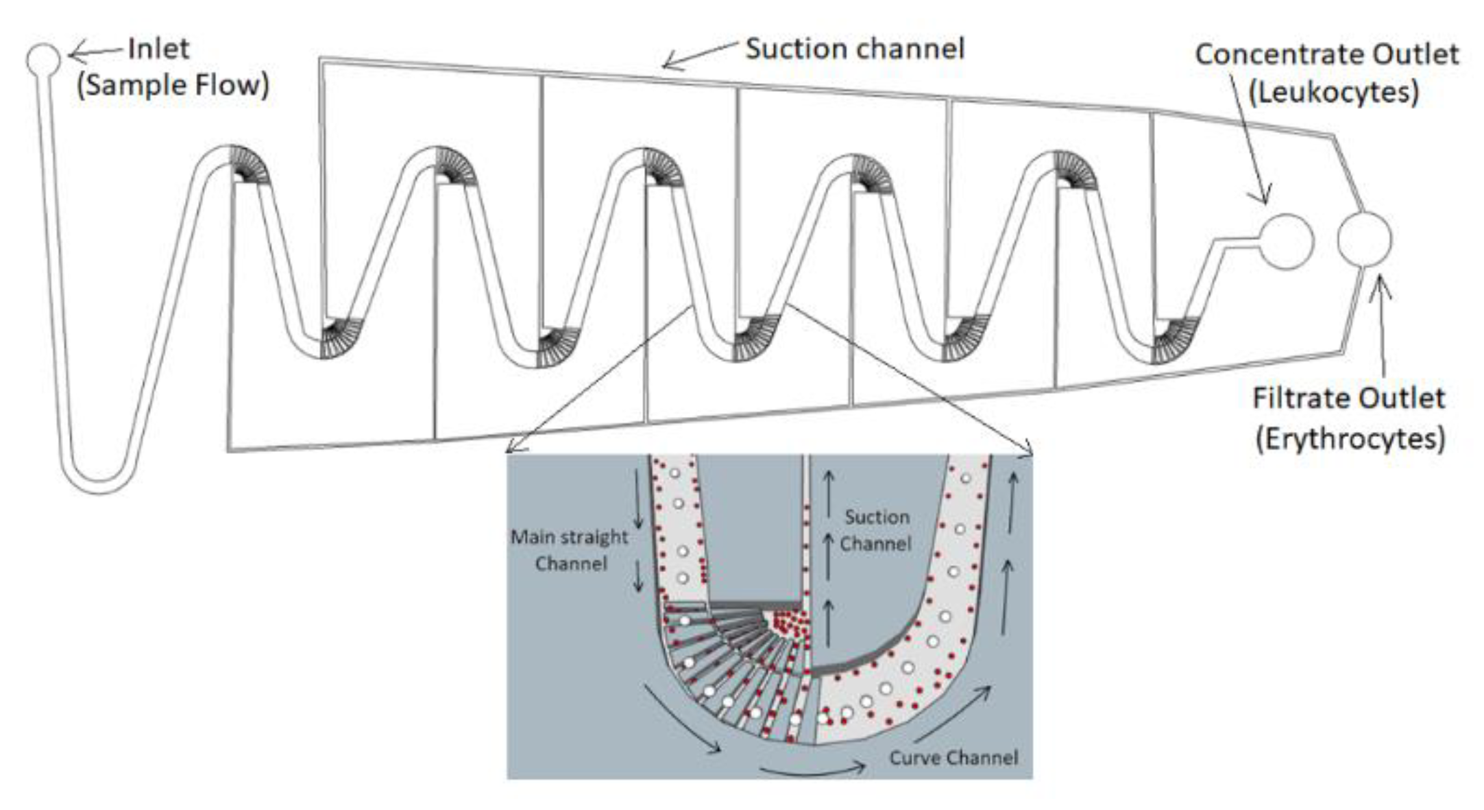
2. Device Design and Working Principle

Figure 1 depicts the design of our separation chip with three types of channel: (i) a main straight channel, (ii) curve channels, and (iii) suction channels. Each type of the channel plays different roles to separate the cells. The whole separation chip consists of ten switchback curve channels connected by the main straight channel. The sample flow is injected from the inlet, passes through the main channel, then through the curve channel, which has the sample flow eventually injecting higher concentrations into the “concentrate outlet”. Meanwhile, each curve channel has one suction channel at the inner curve with all suction channels being connected to draw the smaller blood cells then collected into the filtrate outlet.
(1) Main Straight Channel for Inertial Migration Effect
The main straight channel with rectangular cross sections is located in the entrance, and connects the curve channels. As Poiseuille flow naturally presents in the microchannels, particles/cells usually are acted upon by two fluid dynamic effects—wall-induced lift forces and shear-gradient lift forces—for their discrete equilibrium positions [33,34]. The wall-induced lift forces push the particles/cells away from the walls, while the shear-gradient lift forces push the particles/cells towards the walls [35]. These two effects result the particles/cells with different sizes in equilibrium positions between the channel walls and centerlines, as shown in Figure 2A.
Furthermore, the wall-induced lift force ( F W L ) encountered by the particles/cells can be expressed by Stoke’s law.
F W L = 3 π μ a p U L
where μ is the fluid viscosity, a p is the particle diameter and U L is the minimum fluid velocity to induce the particles moving toward the channel walls.
The shear-gradient lift force ( F S L ) on particles/cells derived from a shear-gradient flow field can be expressed as:
F S L = 2 ρ U f 2 a p 4 D h 2
D h = 4 A P = 2 W H ( W + H )
where ρ is the fluid density, U f is the flow average velocity in a microchannel and D h is the hydraulic diameter for the microchannel.
Based upon the above expressions, the values of these two forces of F W L and F S L depend on the particle/cell sizes ( a p ). By varying the values of these two forces, F W L and F S L differential migration of particles/cells based on their sizes can be utilized for separation. Figure 2B depicts the three possible situations for F W L > F S L , F W L = F S L , and F W L < F S L Moreover, when the cells reach the equilibrium at F W L = F S L , the terminal velocity UL of the cells can be expressed as:
U L = F S L 3 π μ a p = 2 ρ U f 2 a p 3 3 π μ ( 2 W H W + H ) 2
L = U m a x ( 1 2 W ) U L = 3 π W 2 Re ( D h a p ) 3
where U m a x is the maximum velocity in a parabolic flow field, and it is commonly assumed as U m a x ~ 2 U f . L is the channel length required for cells to reach lateral equilibrium position in rectangular channels.
For better separation, a microchannel, whose width is larger than the height (e.g., aspect ratio = (height/width) <1), is devised, leading large lift forces to move cells laterally toward the channel sidewalls for the next stage of the cell separation in the curve channels. The larger lift forces moreover can reduce the channel length required for cell migration and create better cell separation. Thus, our main straight channel is designed by considering a proper Re numbers (e.g., 100 > Re > 1), aspect ratio < 1 and F W L = F S L so the inertial migration can effectively separate RBCs/WBCs within short distances and prepare for the separation in the next curve channels.
A series of the flow rates are tested at 5 μL/sec, 250 μL/sec, and 1.1 mL/sec to evaluate the cell separation performance with the whole blood using the inertial migration effect in the main straight channels. The channel width and height are 200 and 58 μm. Figure 2C demonstrates the results of this preliminary study. It is found that the blood cells distribute quite uniformly at 5 μL/sec (or Re < 1) for Figure 2C(C-1). The blood cells begin to concentrate around the top and bottom walls when the flow rate increases (e.g., 250 μL/sec or 100 > Re > 1 for Figure 2C(C-2). Once the flow rate further increases, the blood cells move and concentrate around the corners of the microchannel (e.g., 1.1 mL/sec or Re > 100) for Figure 2C(C-3). The inertial migration effect is confirmed for our initial RBC/WBC separation.
(2) Curve Channel for Dean Flow
Since the inertial migration could provide a RBCs/WBCs separation efficiency at ~89.8% [36,37] in the straight rectangular channel, a secondary flow by using Dean flow is introduced to further enhance the separation efficiency. A series of curve channels are added to provide Dean flow, which can aid lateral particle/cell migration. Depending on particle/cell size, these secondary Dean flows tend to entrain particles in one of the two vortices formed and force them to follow fluid movement within the vortices. A dimensionless parameter, Dean number (De), is usually defined as:
De = Re D h R
where R is the curvature radius of the curve channel. When De is large enough, the secondary flow forms Dean vortices, vertical to the flow inside the channel. Due to these Dean flows, the drag force exerted on a particle. Larger cells (e.g., WBC) experience larger forces and move toward the outer part of the curve channels; the smaller cells (e.g., RBC) have smaller forces and remain in the inner part.
(3) Suction Channel for Hydrodynamic Suction
When the blood cells move along the curve channels, some of the smaller cells are sucked into the suction channels. To enhance the separation performance in the suction channels, an array of obstacle structures, or trench structures, are induced in the curve channel to create additional secondary flows so better separation can be obtained before the suction. To compare their effects in the cell separation efficiency, two designs—(A) without obstacle and (B) with an array of obstacles—in the curve channels, as illustrated in Figure 3, are tested. In Design (A), although the Dean flow moves the RBCs toward the inner part of the channels, these RBCs mostly keep moving along the curve channel, together with WBCs. Contrarily, in Design (B), some of the RBCs falls inside the trenches (with the height at 15 μm) and are guided into the suction channels, while the WBCs roll over the obstacles and keep moving along the main channel. As a result, some of the RBCs are removed from the sample flow, while the rest of the blood cells stay downstream for further separation. The RBCs can be collected from the suction channels and the recovery rate can be enhanced.
Finally, our device has Dean number (De) approximately set at 11.33, as the radius of the curvature is 200 μm. This Dean number is in the range for Dean flow effect in the curve channel with the geometric parameters of the straight and the curve channels, as well as the flow rate.

3. Material and Methods

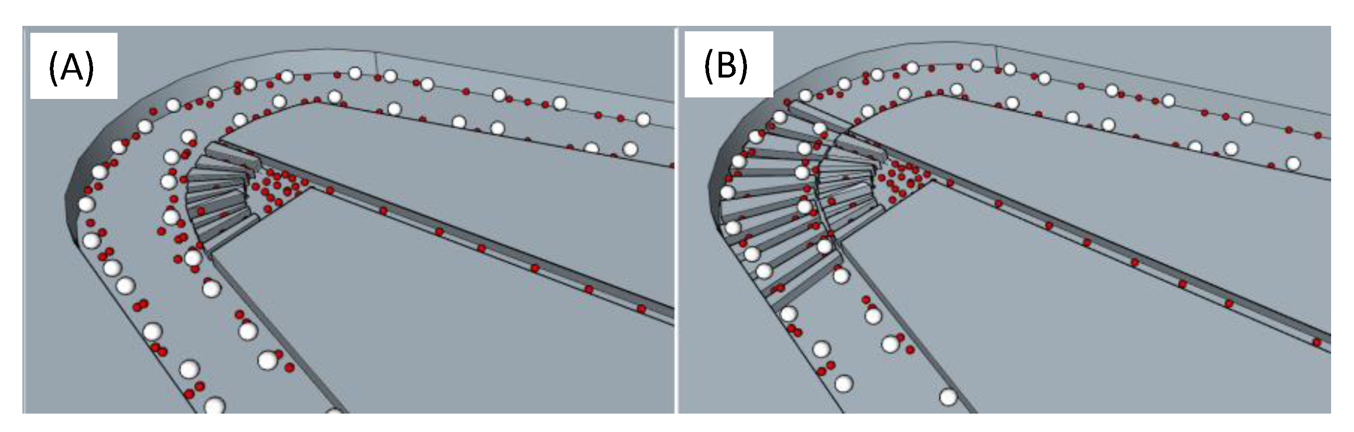
3.1. Fabrication of Our Separation Microchip

To create the main straight channels and curve channels, the molds were first fabricated by patterning two layers of SU-8 3050 (Nippon Kayaku, Tokyo, Japan) negative photoresists on silicon wafers. Polydimethylsiloxane (PDMS, Sylgard 184, Dow Corning, Midland, MI, USA) prepolymer was mixed in 10:1 (w/w) ratio then poured onto the molds for curing for 2 h at 85 °C. The PDMS structures were released at room temperature to reduce thermal stresses. Finally, the holes for inlets and outlets were punched with the PDMS molds irreversibly bonded to microscopic glass slides by briefly exposing them to an oxygen plasma. The devices were left at room temperature for eight hours before usage to avoid any further deformation. The whole process flow was illustrated in Figure 4.

3.2. Sample Preparation

Human whole blood, drawn from donors, was mixed with EDTA (Trtriplex®, Merck, Kennersburg, NJ, USA) as anticoagulant; the ratio of EDTA to blood is 10:1. The cell concentration was measured at 4.3 × 10⁸ cells/mL using cell counter plates.

3.3. Experimental Setup

The sample flow of the whole blood was introduced into our separation chip. A syringe connected to a device with 1/16″ peek tubing and fittings (Upchurch Scientific, Oak Harbor, WA, USA) provided input flow using a syringe pump (KD Scientific, Holliston, MA, USA). Prior to the experiment, 95% alcohol was injected into the microchannel for pre-treatment with the sample solution injected. The flow behavior was first visualized using an inverted epi-fluorescence microscope (IX71, Olympus Inc., Tokyo, Japan) equipped with a 12-bit high-speed charge-coupled device (CCD) camera. To image cross-sectional flow, confocal microscopy was performed using Zeiss LSM710 LIVE Duo Confocal Microscope with the aforementioned experimental set-up. Cross-sectional images were taken at each micro channel main and section. The images were acquired at resolution of 1024 × 768 pixels.

3.4. Recovery Rate

Recovery rate is one of the most common parameters to quantify the separation efficiency. The recovery rate is defined as the ratio of the number of the cells retrieved from the target outlet to the number of the cells introduced into the inlet.
Recovery   rate =   ( N target ) Outlet ( N target ) Inlet × 100 %
where N target was the number of the target cells (e.g., cells of the interests, or WBC in this work).

4. Results and Discussion

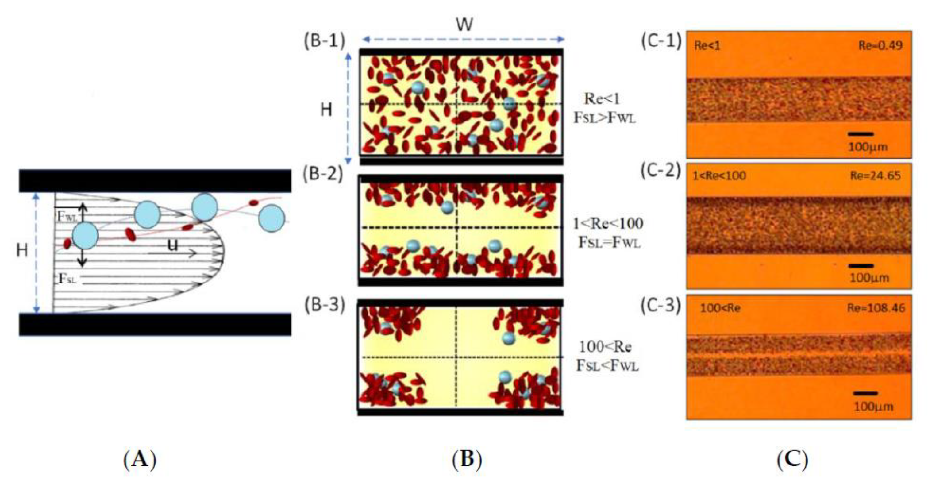
4.1. Inertial Migration Effect

To investigate the relationship between flow velocity and channel length required for cells totally migrating toward the side of the wall, Reynolds number should be greater than one (1) to ensure the occurrence of this hydrodynamic phenomenon.
Experimental evidence from Figure 5A(A-1–A-3) show the blood separation results when the sample solution is injected at 5 μL/sec, 250 μL/sec and 1.1 mL/sec flow rates (Qi). Lateral movements of the cells become obvious, as the flow rates increase. In other words, the lift forces are larger than the drag forces (FL > FD) to push the cells moving laterally toward the channel walls at high flow rate, or Re > 100, as shown in Figure 5A(A-3). On the other hand, the lift forces are smaller (FL < FD) at low flow rate, or Re < 1
Meanwhile, to identify the effect of the cell concentration, various concentrations at 109 cells/mL, 108 cells/mL and 103 cells/mL are tested, with the results shown in Figure 5B. At cell concentration of 108 cells/mL and flow rate 250 μL/sec, the device provides a separation condition with most of the cells accumulated close to the upper and lower channel walls. It is noted that channel irregularities from the fabrication and unexpected changes in boundary conditions that sometimes create flow deformations or uneven cell distribution, as seen in Figure 5A(A-2,A-3),B(B-2).

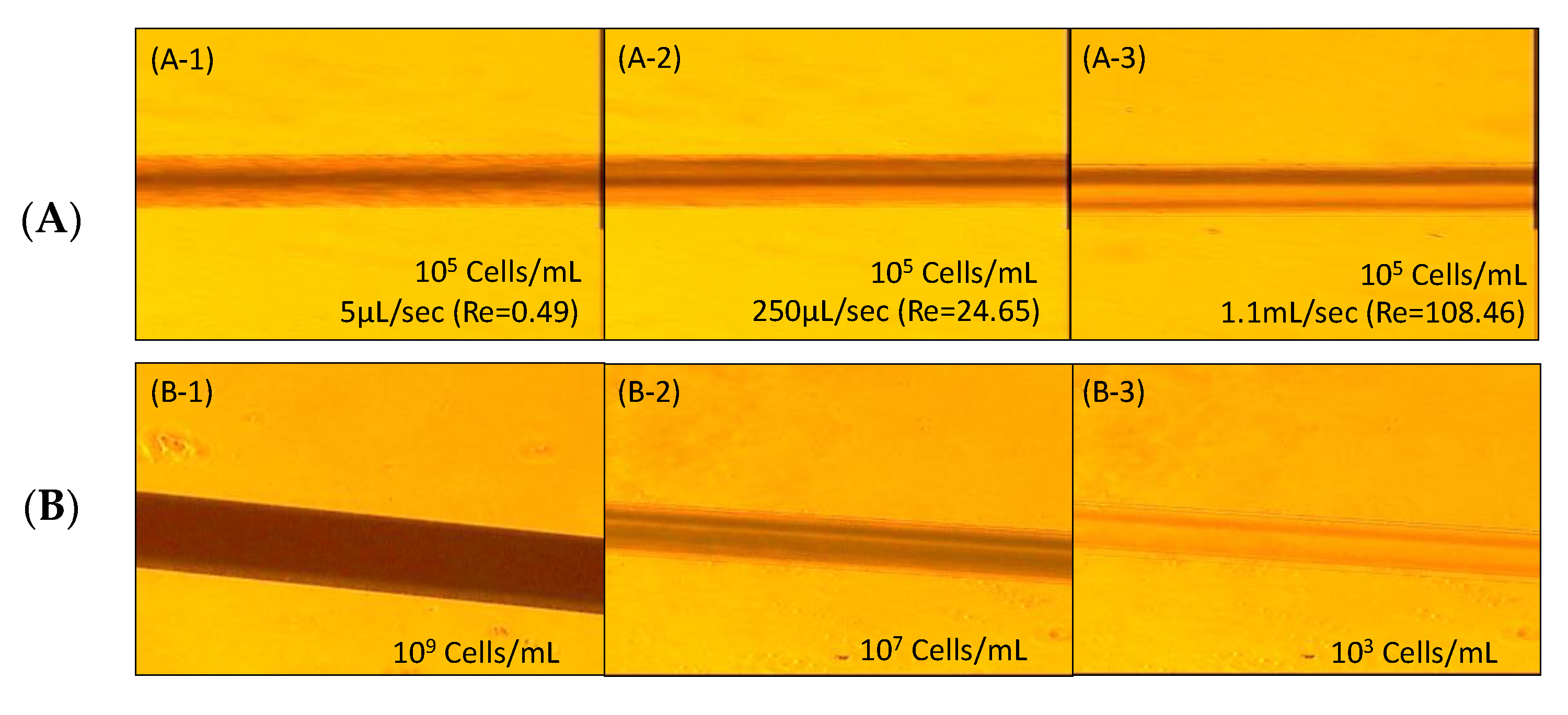
4.2. Separation Efficiency with Hydrodynamic Suction

To realize the hydrodynamic suction effects and the separation efficiencies, two different chip designs (e.g., Chip 1 and Chip 2) with a total of 48 chips were tested. Their critical dimensions, including channel width, height, and length were listed in Table 1. Both chip designs were utilized in different flow rate conditions (5 µL/sec, 20 µL/sec, 250 µL/sec and 1.1 mL/sec for Chip 1; 5 µL/sec, 20 µL/sec, 100 µL/sec and 1.1 mL/sec for Chip 2). The optimal flow rates (based on their separation distribution in the main straight channels by visual examinations) were found at 250 µL/sec for Chip 1 and 100 µL/sec for Chip 2.
The blood cell separation in the curve channel was examined under an optical microscope. Figure 6 showed the image taken during a test where RBCs and WBCs flow into a curve channel using Chip 1. When Re > 100, the blood cells in the main straight channel would be moving and focused near the corners in the microchannels due to the inertial migration effect. This inertial migration effect increases the number of red blood cells that enter the suction channel, and enhances the cell separation. The larger cells (e.g., WBC and others) move long the curve channels (as shown in the yellow arrows), while a portion of the smaller cells (e.g., RBC) move into the suction channels (as shown by the green arrows).
Furthermore, different suction flow rates (Qs) were tested to evaluate the separation efficiencies, as depicted in Figure 7. Three experiments were conducted. The ratio of RBCs/WBCs was used as the indicator for separation efficiency, since a low value of RBCs/WBCs represented fewer RBCs and more WBCs in the outlet. A local optimal separation efficiency was found at Qi/Qs = 5.4 for Chip 1, and Qi/Qs = 1.7 for Chip 2 (the 1st test), and Qi/Qs = 3.7 for Chip 2 (the 2nd tests). In other words, when the suction flow rates were too high or too low, the separation efficiencies may not be better than the one with the optimal suction flow rates. This could be because only a few RBCs were removed from the curve channels into the suction channels when Qs was low. Contrarily, although more RBCs were moved into the suction channels, some of the WBCs in the sample flows also were removed into the suction channels when Qs was high, leading the decrease of the separation efficiencies. As the result, the optimal suction flow was found at 37 µL/sec for Chip 1, and at 58 or 27 µL/sec for Chip 2. The separation efficiencies (or RBCs/WBCs) were about 64 for Chip 1, and 40 or 18 for Chip 2.

4.3. Overall Separation Efficiency

The separation performance of the chip was then examined. Figure 8 showed the recovery rates of RBCs and WBCs when the sample flow passed through each curve channel—from the first curve channel to the tenth curve channel, using Chip 2. Passing through the first curve channel, the sample flow had 99.7% of RBCs. It decreased to 85.8% of RBCs when it passed through the second curve channels, or 14.2% of RBCs were removed through the suction channel. It further decreased to 75.4%, or 24.6% of RBCs were removed after the third curve channel. It continued to decrease to 10.2% after the ninth curve channel, and to 0.1% after the tenth curve channel. Therefore, almost all the RBCs in the sample flow were removed through the suction channels after they passed through 10 curve channels.
On the other hand, the sample flow had 96.2% of WBCs remaining after the first curve channel. The percentage decreased a little bit after every curve channel, and it decreased to 93.2% of WBCs still remaining after the tenth curve channel. The results show a very high recovery rate for WBCs, while very few RBCs were found after the separation chip.
To compare the separation performance, Table 2 exemplifies some of existing inertial and other cell/particle separation techniques in microfluidics. In particular for the separation of biological cells, Y.-Y. Chiu et al. demonstrate hydrodynamic-focusing cross-flow filters in a microfluidic chip to separate PC3 cells from the sample flow (PC3 cells mixed in whole bloods) with a ~94% recovery rate, but at 40 μL/min (or cell processing rate at 4 × 10⁶ cells/sec) [14]. Another research works for cell separation present with a high throughput with processing rates at 7.5 × 10⁶ cells/sec for larger cancer cells spiked in blood from the smaller blood cells [16]. S.Y. Choi and J.K Park report a hydrophoretic filtration device using slanted obstacles to separate WBCs and RBCs from the whole blood with a purity of 76.8% [19]. The flow rate is 1 μL/sec (or cell processing rate at approximate 1 × 10⁸ cells/sec), with over one hour of operation with a recovery rate at 30%. Comparatively, our chip shows great improvement in purity and recovery rate at a high processing rate, or higher throughput in biological cell separation.
As inertial microfluidics (i.e., inertial migration and Dean flow) is a fast-growing field, many related non-linear fluid physics and basic directions are still uncharted. For instance, some analytical models have been presented for straight and curve microchannels for particle/cell separation, but our devices must be re-designed and fabricated for the separations whenever the threshold sizes of the particles/cells change. The flow conditions of the injection and suction flow rates must be experimentally optimized. This is an inherent limitation of our passive inertial microfluidic devices. Also, the physics of how the secondary flow and cell trapping in an obstacle array are created and affected by obstacle arrangement and geometrical parameters is complicated and yet to be understood. Further optimization can be also experimentally conducted for even higher throughput or separation efficiency on these related design variables. Additionally, the interaction of Dean drag and lift forces within the microchannel and related flow condition and channel geometry require diligent experiments. Channel irregularities from the fabrication and unexpected changes in boundary conditions that create flow deformations or uneven cell distribution offer a vast number of other aspects to be studied.

5. Conclusions

We have demonstrated a microfluidic device, which can remove most of the RBCs from whole blood by employing the inertial migration effect, Dean flow, and hydrodynamic suction. An array of obstacles was created in the curve channels, which redirected the RBCs to move into the suction channels. A 93.2% recovery rate of WBCs and very few RBCs in the sample flow were obtained in a high operation flow rate (e.g., 250 μL/sec). Our separation technique, therefore, was advantageous for continuous processing, while reducing the clogging problem—a problem commonly seen in particle separation using a microchannel. Additionally, it provided advantages over conventional methods by scaling down the instrumentation size, simplifying the operation procedures for automation, as well as enabling the downstream integration for cellular isolation, analysis, and processing. It is expected that the results from this work will benefit a wide range of analytical, environmental, biological, and manufacturing applications that require rapid, low-cost, continuous filtration, and/or separation of microscale objects.

Author Contributions

Conceptualization, B.G.; Data curation, B.L., H.-Y.C., C.-W.L. and R.-G.W.; Formal analysis, H.C.T. and C.-W.L.; Methodology, N.T.; Project administration, F.-G.T.; Writing – review & editing, Y.-W.L. All authors have read and agreed to the published version of the manuscript.

Acknowledgments

This research was funded by Ministry of Science and Technology MOST 106-2923-E-007 -004 -MY3). The IRB number is 10607HM063, which was permitted by Research Ethics Committee in National Tsing Hua University. The project was conducted from September 2017 to September 2019. The authors also thank Theresa Kirk for manuscript editing.

Conflicts of Interest

The authors declare no conflict of interest.

References

  1. Anker, P.; Mulcahy, H.; Chen, X.Q.; Stroun, M. Detection of circulating tumour DNA in the blood (plasma/serum) of cancer patients. Cancer Metastasis Rev. 1999, 18, 65–73. [Google Scholar] [CrossRef]
  2. Bhagat, A.A.; Kuntaegowdanahalli, S.S.; Papautsky, I. Continuous particle separation in spiral microchannels using Dean flows and differential migration. Lab Chip 2008, 8, 1906–1914. [Google Scholar] [CrossRef]
  3. Hou, H.W.; Bhagat, A.A.S.; Lee, W.C.; Huang, S.; Han, J.; Lim, C.T. Microfluidic Devices for Blood Fractionation. Micromachines 2011, 2, 319–343. [Google Scholar] [CrossRef] [Green Version]
  4. Catarino, S.O.; Rodrigues, R.O.; Pinho, D.; Miranda, J.M.; Minas, G.; Lima, R. Blood cells separation and sorting techniques of passive microfluidic devices: From fabrication to applications. Micromachines 2019, 10, 593. [Google Scholar] [CrossRef] [Green Version]
  5. Lin, C.-H.; Lee, C.-Y.; Tsai, C.-H.; Fu, L.-M. Novel continuous particle sorting in microfluidic chip utilizing cascaded squeeze effect. Microfluid. Nanofluidics 2009, 7, 499–508. [Google Scholar] [CrossRef]
  6. Yamada, M.; Seki, M. Hydrodynamic filtration for on-chip particle concentration and classification utilizing microfluidics. Lab Chip 2005, 5, 1233–1239. [Google Scholar] [CrossRef]
  7. Morijiri, T.; Sunahiro, S.; Senaha, M.; Yamada, M.; Seki, M. Sedimentation pinched-flow fractionation for size- and density-based particle sorting in microchannels. Microfluid. Nanofluidics 2011, 11, 105–110. [Google Scholar] [CrossRef]
  8. Lin, B.K.; McFaul, S.M.; Jin, C.; Black, P.C.; Ma, H.S. Highly selective biomechanical separation of cancer cells from leukocytes using microfluidic ratchets and hydrodynamic concentrator. Biomicrofluidics 2013, 7, 034114. [Google Scholar] [CrossRef] [Green Version]
  9. Takagi, J.; Yamada, M.; Yasuda, M.; Seki, M. Continuous particle separation in a microchannel having asymmetrically arranged multiple branches. Lab Chip 2005, 5, 778–784. [Google Scholar] [CrossRef]
  10. Chen, X.; Cui, D.; Liu, C.; Li, H. Microfluidic chip for blood cell separation and collection based on crossflow filtration. Sens. Actuators B Chem. 2008, 130, 216–221. [Google Scholar] [CrossRef]
  11. Sollier, E.; Rostaing, H.; Pouteau, P.; Fouillet, Y.; Achard, J.-L. Passive microfluidic devices for plasma extraction from whole human blood. Sens. Actuators B Chem. 2009, 141, 617–624. [Google Scholar] [CrossRef]
  12. Alvankarian, J.; Bahadorimehr, A.; Majlis, B.Y. A pillar-based microfilter for isolation of white blood cells on elastomeric substrate. Biomicrofluidics 2013, 7, 14102. [Google Scholar] [CrossRef] [Green Version]
  13. Li, X.; Chen, W.; Liu, G.; Lu, W.; Fu, J. Continuous-flow microfluidic blood cell sorting for unprocessed whole blood using surface-micromachined microfiltration membranes. Lab Chip 2014, 14, 2565–2575. [Google Scholar] [CrossRef] [Green Version]
  14. Chiu, Y.-Y.; Huang, C.-K.; Lu, Y.-W. Enhancement of microfluidic particle separation using cross-flow filters with hydrodynamic focusing. Biomicrofluidics 2016, 10, 011906. [Google Scholar] [CrossRef]
  15. Chen, C.L.; Chen, K.C.; Pan, Y.C.; Lee, T.P.; Hsiung, L.C.; Lin, C.M.; Wo, A.M. Separation and detection of rare cells in a microfluidic disk via negative selection. Lab Chip 2011, 11, 474–483. [Google Scholar] [CrossRef]
  16. Hur, S.C.; Mach, A.J.; di Carlo, D. High-throughput size-based rare cell enrichment using microscale vortices. Biomicrofluidics 2011, 5, 022206. [Google Scholar] [CrossRef] [Green Version]
  17. Zhou, J.; Kasper, S.; Papautsky, I. Enhanced size-dependent trapping of particles using microvortices. Microfluid. Nanofluidics 2013, 15, 611–623. [Google Scholar] [CrossRef] [Green Version]
  18. Hahn, Y.; Hong, D.; Kang, J.; Choi, S. A reconfigurable microfluidics platform for microparticle separation and fluid mixing. Micromachines 2016, 7, 139. [Google Scholar] [CrossRef] [Green Version]
  19. Choi, S.; Park, J.-K. Continuous hydrophoretic separation and sizing of microparticles using slanted obstacles in a microchannel. Lab Chip 2007, 7, 890–897. [Google Scholar] [CrossRef]
  20. Di Carlo, D.; Edd, J.F.; Irimia, D.; Tompkins, R.G.; Toner, M. Equilibrium separation and filtration of particles using differential inertial focusing. Anal. Chem. 2008, 80, 2204–2211. [Google Scholar] [CrossRef]
  21. Ramachandraiah, H.; Ardabili, S.; Faridi, A.M.; Gantelius, J.; Kowalewski, J.M.; Mårtensson, G.; Russom, A. Dean flow-coupled inertial focusing in curved channels. Biomicrofluidics 2014, 8, 034117. [Google Scholar] [CrossRef] [Green Version]
  22. Sun, J.; Li, M.; Liu, C.; Zhang, Y.; Liu, D.; Liu, W.; Jiang, X. Double spiral microchannel for label-free tumor cell separation and enrichment. Lab Chip 2012, 12, 3952–3960. [Google Scholar] [CrossRef] [Green Version]
  23. Warkiani, M.E.; Guan, G.; Luan, K.B.; Lee, W.C.; Bhagat, A.A.S.; Chaudhuri, P.K.; Lim, C.T. Slanted spiral microfluidics for the ultra-fast, label-free isolation of circulating tumor cells. Lab Chip 2014, 14, 128–137. [Google Scholar] [CrossRef] [Green Version]
  24. Kim, T.H.; Yoon, H.J.; Stella, P.; Nagrath, S. Cascaded spiral microfluidic device for deterministic and high purity continuous separation of circulating tumor cells. Biomicrofluidics 2014, 8, 064117. [Google Scholar] [CrossRef] [Green Version]
  25. Burke, J.M.; Zubajlo, R.E.; Smela, E.; White, I.M. High-throughput particle separation and concentration using spiral inertial filtration. Biomicrofluidics 2014, 8, 024105. [Google Scholar] [CrossRef] [Green Version]
  26. Vasseur, P.; Cox, R.G. The lateral migration of spherical particles sedimenting in a stagnant bounded fluid. J. Fluid Mech. 2006, 80, 561–591. [Google Scholar] [CrossRef]
  27. Yang, S.; Lee, S.S.; Ahn, S.W.; Kang, K.; Shim, W.; Lee, G.; Kim, J.M. Deformability-selective particle entrainment and separation in a rectangular microchannel using medium viscoelasticity. Soft Matter 2012, 8, 5011–5019. [Google Scholar] [CrossRef]
  28. Chung, A.J. A Minireview on inertial microfluidics fundamentals: Inertial particle focusing and secondary flow. BioChip J. 2019, 13, 53–63. [Google Scholar] [CrossRef]
  29. Zhou, J.; Papautsky, I. Fundamentals of inertial focusing in microchannels. Lab Chip 2013, 13, 1121–1132. [Google Scholar] [CrossRef]
  30. Chen, Y.-L. Inertia- and deformation-driven migration of a soft particle in confined shear and Poiseuille flow. RSC Adv. 2014, 4, 17908–17916. [Google Scholar] [CrossRef]
  31. Zhang, J.; Yan, S.; Sluyter, R.; Li, W.; Alici, G.; Nguyen, N.T. Inertial particle separation by differential equilibrium positions in a symmetrical serpentine micro-channel. Sci. Rep. 2014, 4, 4527. [Google Scholar] [CrossRef] [PubMed] [Green Version]
  32. Yoon, D.H.; Ha, J.B.; Bahk, Y.K.; Arakawa, T.; Shoji, S.; Go, J.S. Size-selective separation of micro beads by utilizing secondary flow in a curved rectangular microchannel. Lab Chip 2009, 9, 87–90. [Google Scholar] [CrossRef] [PubMed]
  33. Cruz, J.; Graells, T.; Walldén, M.; Hjort, K. Inertial focusing with sub-micron resolution for separation of bacteria. Lab Chip 2019, 19, 1257–1266. [Google Scholar] [CrossRef] [PubMed] [Green Version]
  34. Amini, H.; Sollier, E.; Weaver, W.M.; di Carlo, D. Intrinsic particle-induced lateral transport in microchannels. Proc. Natl. Acad. Sci. USA 2012, 109, 11593–11598. [Google Scholar] [CrossRef] [PubMed] [Green Version]
  35. Liu, C.; Hu, G. High-throughput particle manipulation based on hydrodynamic effects in microchannels. Micromachines 2017, 8, 73. [Google Scholar] [CrossRef] [Green Version]
  36. Zhang, J.; Li, W.; Alici, G. Inertial microfluidics: Mechanisms and applications. In Advanced Mechatronics and MEMS Devices II; Springer: Berlin/Heidelberg, Germany, 2017; pp. 563–593. [Google Scholar]
  37. Lee, D.J.; Brenner, H.; Youn, J.R.; Song, Y.S. Multiplex particle focusing via hydrodynamic force in viscoelastic fluids. Sci. Rep. 2013, 3, 3258. [Google Scholar] [CrossRef] [PubMed] [Green Version]
Figure 1. Our separation chip has three types of channel: (i) a main straight channel, (ii) curve channels, and (iii) suction channels. The main straight channel has the inertial migration to move the cells into different equilibrium regions. The curve channels (with the close-up view in the inset) push the white blood cells (WBCs) toward the outer part while the red blood cells (RBCs) move toward the inner part. The suction channel allows the RBCs to be sucked away. Note: the main dimensions of the microchannels used in this work are: W = 200 μm, H = 58 or 85 μm, radius of curvature = 100 μm, and W (suction) = 7 μm.
Micromachines 11 00275 g001
Figure 2. (A) A particle/cell experiences the wall-induced lift force (FWL) and shear-gradient lift force (FSL) inside a microchannel with a WxH cross section. The small particles/cells (e.g., RBC) tend to move toward the corners of the microchannel as the lift forces are larger than the drag forces. The large particles/cells (e.g., WBC) tend to move toward the outer region of the microchannels. (B) Due to the inertial migration effect, the cells with different sizes move into different cross-sectional regions in the microchannel. Based on the relationship between FD and FL, the cells are: (B-1) uniformly distributed, when FSL > FWL, or Re < 1; (B-2) close to the top and bottom walls of the microchannels, when FSL = FWL, or 100 > Re > 1; and (B-3) around the corners of the microchannels when FSL < FWL, Re > 100. (C) The microscopy views of the whole bloods flowing in the microchannel with (C-1) blood cells distribute uniformly at 5 μL/sec or Re < 1; (C-2) blood cells concentrate close to the top, bottom and sidewall surfaces at 250 μL/sec, or 100 > Re > 1; (C-3) blood cells concentrate around the corner of the microchannel at 1.1 mL/sec, or Re > 100.
Micromachines 11 00275 g002
Figure 3. When the blood cells move along the curve channels, some of the smaller cells are sucked into the suction channels. Two designs—(A) without obstacle and (B) with an array of obstacles—are tested to compare the suction efficiency in the curve channels.
Micromachines 11 00275 g003
Figure 4. Fabrication process of the blood cells separation device. I-III are the steps for standard lithography with the negative photoresist SU8. IV–V are the steps for soft lithography with polydimethylsiloxane (PDMS) and then bonding the device on a glass substrate after plasma treatment. Note: (I–III), the SU8 process follows the standard procedure, provided from official data sheet. A two layers of SU8 are made: a first SU8 layer with a 20–50 μm thickness is spun-coated at 1500 rpm, exposed and baked; a second SU8 layer is then coated upon, exposed and baked with similar processing parameters.
Micromachines 11 00275 g004
Figure 5. Inertial migration effect in whole blood separation (A) with different flow rate, and (B) with different blood cells concentration.
Micromachines 11 00275 g005
Figure 6. Blood cell separation in the curve channel. Once the sample flow moves along the curve channel, small cells (e.g., RBC) move along the suction channels (green arrow), while larger cells (e.g., WBC and others) move long the curve channels (yellow arrow). Qi = 100 µL/sec; Qs = 20 µL/sec. Chip 1 is used here as an example.
Micromachines 11 00275 g006
Figure 7. Separation efficiencies to the ratio of injection (Qi) and suction (Qs) flow rates for Chip 1 and Chip 2. (Note: Chip 1 has no obstacle in the curve channels; Chip 2 has obstacles in the curve channels). (Note: Chip 2 (1st and 2nd) has two optimum, as the conditions of the blood samples vary between the 1st and 2nd tests.).
Micromachines 11 00275 g007
Figure 8. The recovery rate of the RBCs and WBCs in the sample flow after the curve/suction channels—from the first to the tenth curve channels.
Micromachines 11 00275 g008
Table 1. Parameters used for blood cell separation using Chip 1 and Chip 2.
Microchannel
Dimension (µm)
Obstacle
in Curve Channel
Sample Solution
(Whole Blood)
Flow Rate
(µL/sec)
Chip 1W × H = 200 × 58
R = 200
NO
(shown in Figure 3A)
4.3 × 10⁸ cells/mL5, 20, 250, 1100
Chip 2W × H = 200 × 85
R = 100
YES
(shown in Figure 3B)
4.3 × 10⁹ cells/mL5, 20, 100, 1100
Table 2. Comparison of some existing microfluidic techniques for particle/cell separation.
Channel TypeMechanismParticles/Cell Size (D = diameter in μm)Channel
Dimension (μm)
Width (W) ×
Height (H)
Flow Rate
(or Throughput)
Recovery Rate, or Capture Efficiency (η)Ref
Channel with filtersHydrodynamic focusing, filtrationPC3 cells in whole bloods.W = 100,
H = 30
Wgap = 4 (filter)
10 μL/min94.5%
(PC3 cells)
[14]
Trapping reservoirInertial/
Trapping by vortices
MCF7 cells; HeLa cells W = 50
H = 70 m
7.5 × 10⁶
cells/sec
η = 10% (HeLa)
η = 23% (MCF7)
[16]
Asymmetric serpentineDifferential inertial focusingPolystyrene beads
(D = 3.1, 9.0)
W = 100~650
H = 50
~1.0 mL/min~56% (3.1 μm particle, two tiers)[20]
Double spiralDean flowMCF-7, Hela
in whole blood
W = 300
H = 50
3.33 × 10⁷ cells/min88.5% [22]
Slanted spiral Dean flowT24, MCF-7, MDA-MB-231 in bloodW = 600;
H = 80 /130
(inner/outer)
1700 μL/min.η = 80% (T24)
85% (MCF-7)
87% (MDA-MB-231).
[23]
Symmetrical serpentine Inertialpolystyrene beads
(D = 3, 10; 5, 13)
W = 200
H = 42
600 μL/min>97% (large particles);
>92% (small particles)
[31]
Serpentine with Suction channel Inertial,
Dean flow and suction
RBC, WBC
(D = 8, 15).
W = 200
H = 58
1 × 10⁸ cells/sec, or 250 μL/sec93.2%Our Work

