Fabrication and Characterization of Flexible Thermoelectric Generators Using Micromachining and Electroplating Techniques

1
Department of Mechanical Engineering, National Chung Hsing University, Taichung 402, Taiwan
2
Department of Biomedical Engineering, National Taiwan University, Taipei 106, Taiwan
3
Department of Electro-Optical Engineering, National United University, Miaoli 360, Taiwan
*
Author to whom correspondence should be addressed.
Micromachines 2019, 10(10), 660; https://doi.org/10.3390/mi10100660
Submission received: 20 August 2019
/
Revised: 27 September 2019
/
Accepted: 29 September 2019
/
Published: 30 September 2019
(This article belongs to the Special Issue 10th Anniversary of Micromachines)
Abstract
:This study involves the fabrication and measurement of a flexible thermoelectric generator (FTG) using micromachining and electroplating processes. The area of the FTG is 46 × 17 mm2, and it is composed of 39 thermocouples in series. The thermoelectric materials that are used for the FTG are copper and nickel. The fabrication process involves patterning a silver seed layer on the polymethyl methacrylate (PMMA) substrate using a computer numerical control (CNC) micro-milling machine. Thermoelectric materials, copper and nickel, are deposited on the PMMA substrate using an electroplating process. An epoxy polymer is then coated onto the PMMA substrate. Acetone solution is then used to etch the PMMA substrate and to transfer the thermocouples to the flexible epoxy film. The FTG generates an output voltage (OV) as the thermocouples have a temperature difference (ΔT) between the cold and hot parts. The experiments show that the OV of the FTG is 4.2 mV at ΔT of 5.3 K and the output power is 429 nW at ΔT of 5.3 K. The FTG has a voltage factor of 1 μV/mm2K and a power factor of 19.5 pW/mm2K2. The FTG reaches a curvature of 20 m−1.
1. Introduction
Many recent studies have focused on the development of thermoelectric generators [1,2,3,4,5,6,7,8]. Thermoelectric generators are used to convert waste heat into electrical power, which is a green energy. It is difficult to use a non-flexible thermoelectric generator for a heat source with a curved surface because it does not fit the curved surface. However, a flexible thermoelectric generator can be used for a heat source with a curved surface and has more applications than a non-flexible thermoelectric generator. Flexible thermoelectric generators can be used as a wearable device to fit the curves of human skin.
Various fabrication methods were used for thermoelectric generators. For instance, Lee [9] used a screen printing method to produce a thermoelectric generator using the thermoelectric materials, ZnSb and CoSb3, on an alumina substrate. The output voltage (OV) for the thermoelectric generator was 10 mV at ΔT of 50 K, and its output power per unit area was 1.7 μW/mm2 at temperature difference (ΔT) of 50 K. The power factor of the thermoelectric generator was 0.68 pW/mm2K2. Phaga [10] developed a thermoelectric generator that had 31 thermocouples in series. The thermocouple materials were p-Ca3Co4O9 and n-CaMnO3 that were deposited by the solid state reaction method. The area of the thermoelectric generator was 6.45 cm2. The OV for the thermoelectric generator was 121.7 mV at ΔT of 140 K and the output power was 1.47 μW at ΔT of 140 K. The voltage factor for the thermoelectric generator was 1.35 μV/mm2K and the power factor was 0.16 pW/mm2K2. Big-Alabo [11] produced a thermoelectric generator using low pressure chemical vapor deposition and a micro-fabrication process [12]. Ge and SiGe were the thermoelectric materials. The thermoelectric generator had an estimated power density of 111 nW/cm2 and a power factor of 0.0035 μW/cm2K2. Itoigawa [13] proposed a flexible thermoelectric generator that was fabricated on a polyimide substrate using a micro-fabrication process. The thermoelectric materials for the generator were copper and nickel. The generator contained 380 thermocouples in series, and its area was about 50 × 50 mm2. The generator had a bending radius of curvature of 9 mm. The OV and output power were 16 μV/K per thermocouple and 4.1 pW/K2 per thermocouple, respectively. Therefore, the thermoelectric generator had a voltage factor of 2.43 μV/mm2K and a power factor of 0.64 pW/mm2K2. A flexible thermoelectric generator, developed by Lu [14], was fabricated using physical mixing and drop casting processes. The thermoelectric materials for the generator were Te/poly(3,4-ethylenedioxythiophene) and poly(styrenesulfonate) /Cu7Te4 ternary composite films. The flexible thermoelectric generator (FTG) consisted of eight thermopiles with Ag paste and the area was about 25 × 40 mm2. The OV for the generator was 31.2 mV at ΔT of 39 K and the maximum output power was 94.7 nW at ΔT of 39 K. The FTG had a power factor of 112.3 μW/mK2. Ding [15] manufactured a flexible thermoelectric generator on a nylon membrane. The thermoelectric material of the generator was n-type Ag2Se. The FTG contained four legs of the Ag2Se film that were connected with Ag paste on a nylon substrate and the area of the FTG was about 20 × 20 mm2. The OV and the maximum output power for the FTG were 18 mV and 460 nW, respectively, at ΔT of 30 K. The voltage factor, the FTG was 1.5 μV/mm2K and the power factor was 1.2 pW/mm2K2. Selvan [16] manufactured a thermoelectric generator on a polyimide substrate using a microfabrication process. Cobalt and copper were used as negative and positive thermoelectric materials for the thermoelectric generator. The generator was a flexible sandwiched planar structure. The power factor for the thermoelectric generator was 6.6 × 10⁻³ μW/cm2K2 at ΔT of 44.2 K. A flexible thermoelectric generator, presented by Jo [17], was made on a polydimethylsiloxane substrate to harvest heat energy from a human body. The materials for the thermocouples in the generator were n-type and p-type Bi2Te3, which were manufactured using dispenser printing. The area of the thermoelectric generator was 50 × 50 mm2. The OV for the generator was 7 mV at ΔT of 19 K and the output power was 2.1 μW at ΔT of 19 K. The thermoelectric generator had a voltage factor of 0.15 μV/mm2K and an output power of 2.33 pW/mm2K2. Oh [18] proposed a flexible thermoelectric generator for self-powered wearable electronics. The materials for the FTG were p-type NbSe2 and n-type WS2 nanosheet films. The flexible thermoelectric generator produced an output power of 38 nW at the ΔT of 60 K and the performance was stable after 100 bending cycles and 100 stretching cycles at a 50% strain. Kim [19] used an optimized composite film with tungsten disulfide nanosheets and single wall carbon nanotubes to fabricate a flexible thermoelectric generator on a rubber substrate with pre-strain. The FTG kept its performance after 10,000 stretching cycles at a 30% strain. These thermoelectric generators [13,14,15,16,17] are flexible and have more applications than non-flexible thermoelectric generators [9,10,11]. This study uses a low cost electroplating process that allows easy fabrication to manufacture a flexible thermoelectric generator on an epoxy substrate. The power factor for the FTG exceeds that for the FTG’s that were developed by Itoigawa [13], Lu [14], Ding [15], and Jo [17].
2. Design for the Thermoelectric Generator
Figure 1 shows the schematic structure of the flexible thermoelectric generator. The FTG is composed of 39 thermocouples in series. Each of the thermocouple is made of copper and nickel. The thermocouples have a hot part and a cold part. Each thermocouple is 7 mm long, 0.5 mm wide, and 0.1 mm thick. The area of the FTG is 46 × 17 mm2. The FTG uses the Seebeck effect to generate an output voltage if the hot and cold parts of the thermocouples have different temperatures. The output voltage for the FTG is given by [20],
where U0 represents the OV for the FTG, m is the number of thermocouples in the FTG, αc is the Seebeck coefficient for copper, αn is the Seebeck coefficient for nickel and ΔT is temperature difference between the hot part and cold parts of the thermocouples. Equation (1) shows that that the OV for the FTG is proportional to the number of thermocouples (m), the difference in the Seebeck coefficients (αc − αn) for the thermocouple materials, and ΔT for the thermocouples [21]. If there is an increase in the three parameters, m, αc − αn and ΔT, the OV for the FTG increases. To increase the temperature difference between the hot and cold parts of thermocouples, the length of the thermocouples is extended to 7 mm. In the design, thermocouple materials are copper and nickel. The Seebeck coefficient of copper is 1.83 μV/K, and the Seebeck coefficient of nickel is −19.5 μV/K [22]. The thermocouple number of the FTG is 39. The values m = 39 and αc − αn = 21.33 μV/K are substituted into Equation (1), the relation between the OV and ΔT of the FTG is obtained. Figure 2 shows the simulated OV of the FTG. In this computation, the temperature difference of thermocouples changes from zero to 5.5 K. As shown in Figure 2, the change between the OV and ΔT was linear relation. The simulated OV of the FTG was 4.6 mV at ΔT of 5.5 K.
The output power of the FTG depends on the internal resistance and the external load. When the internal resistance of the FTG equals its external load, the FTG has a maximum output power. The maximum output power of the FTG is given by [23],
where Pmax is the maximum output power for the FTG, U0 is the OV for the FTG, and Rg is the internal resistance of the FTG. Equation (2) shows that the maximum output power of the FTG is proportional to the square of the OV and is inversely proportional to the internal resistance [24]. If the OV for the FTG is increased and the internal resistance is decreased, the maximum output power increases. The maximum output power for the FTG is calculated. The internal resistance of the FTG is assumed to be 10.3 Ω. The value Rg = 10.3 Ω and the simulated OV in Figure 2 are substituted into Equation (2). The maximum output power for the FTG is calculated and the simulated results are shown in Figure 3. The temperature difference for the thermocouples changes from zero to 5.5 K. Figure 3 shows that the relationship between the output power and temperature difference is nonlinear. The simulated output power for the FTG is 508 nW at ΔT of 5.5 K.
3. Fabrication of the Thermoelectric Generator
The flexible thermoelectric generators were fabricated on an epoxy substrate using an electroplating technique. The structure of the FTG consisted of thermocouples in series. The materials for the thermocouples were copper and nickel. Figure 4 illustrates the process flow for the FTG.
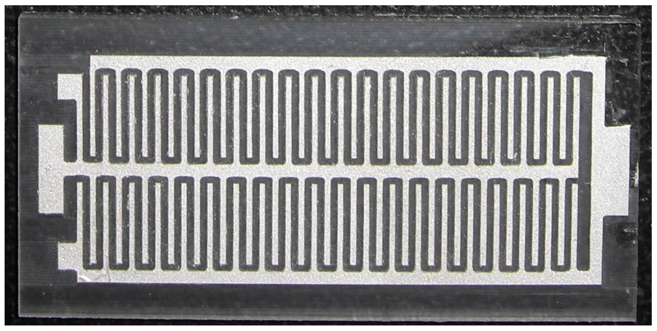
Figure 4a shows a seed layer of silver on the PMMA substrate. The silver seed layer was coated onto the PMMA substrate, and the silver layer was patterned using a computer numerical control (CNC) micro-milling machine. Figure 5 shows an image of the silver layer pattern that is defined by the CNC micro-milling machine. Figure 4b shows that a copper layer is deposited onto the silver layer. An electroplating process with CuSO4 solution and a current density of 4 A/dm2 for 45 min was utilized to deposit the copper layer onto the silver layer. The thickness of the copper layer was 100 μm. Figure 4c shows that a nickel layer is electroplated onto the silver layer. An electroplating process with NiSO4 solution and a current density of 4 A/dm2 for 45 min was employed to deposit the nickel layer onto the silver layer. The thickness of the nickel layer was 100 μm. Figure 4d shows that an epoxy is coated onto the PMMA substrate. Epoxy is used because the PMMA substrate is not flexible so epoxy is used to replace the PMMA substrate. Figure 4e shows etching the PMMA substrate. The FTG was immersed in an acetone solution for 30 min to etch the PMMA substrate and structure of the thermocouples was transferred to the epoxy substrate. Figure 4f shows that silver paint connects the nickel and the copper to form the thermocouples in series. Figure 4g shows that a thin epoxy layer is coated onto the FTG to protect the thermocouples. This layer prevents damage from dust and steam. Figure 6 shows an image of the flexible thermoelectric generator. Figure 7 shows that the FTG is flexible.
4. Results and Discussion
A heater, a cooler, a power supply, an infrared thermometer and a digital multimeter were used to test the OV for the FTG. The heater was placed at the hot part of the thermocouples and the cooler was placed at the cold part of the thermocouples. The power supply provided power to the heater and cooler. The heater acted as a heat source for the hot part of the thermocouples and the cooler acted as a heat sink for the cold part of the thermocouples. An infrared thermometer was used to measure the temperature difference between the hot and cold parts of the thermocouples. A digital multimeter recorded the OV for the FTG.
Figure 8 shows the measured OV for the flexible thermoelectric generator. The temperature difference of the thermocouples in the FTG was varied between zero and 5.3 K. The results show that the OV for the FTG is 2.6 mV at ΔT of 5.3 K. The internal resistance was measured using a digital multimeter. The value was 10.3 Ω. Equation (2) is used to calculate the maximum output power for the FTG. The internal resistance Rg = 10.3 Ω and the measured results for the FTG OV in Figure 8 are substituted into Equation (2) to calculate the maximum output power. Figure 9 shows the measured maximum output power for the flexible thermoelectric generator. The measured maximum output power for the FTG was 165 nW at ΔT of 5.3 K.
As shown in Figure 2 and Figure 8, the simulated OV for the FTG is 4.3 mV at ΔT of 5.3 K and the measured OV is 2.6 mV at ΔT of 5.3 K. A comparison of the simulated and measured results shows that the OV for the FTG has an error percentage of 40%. As shown in Figure 3 and Figure 9, this error results in a large difference between the simulated and the measured maximum output power. The thermoelectric properties of the copper and nickel in the thermocouples depend on the current density during the electroplating process. To reduce the error and improve the thermoelectric properties of the thermocouples, this study uses different values of current density to electroplate the copper and nickel for the FTG and measures the OV. Figure 10 shows the measured OV for the flexible thermoelectric generator for different electroplating current densities. Four current densities are used to electroplate the copper and nickel onto the FTG: 0.5 A/dm2, 1 A/dm2, 2 A/dm2 and 4 A/dm2. The results show that the OV for the FTG increases as the current density that is used for electroplating is decreased. As shown in Figure 10, the FTG produces the greatest OV at a current density of 0.5 A/dm2. The results (0.5 A/dm2) are in agreement with the simulation results. At a current density of 0.5 A/dm2, the FTG produces an OV of 4.2 mV for a value of ΔT of 5.3 K. The voltage factor for the FTG was 1 μV/mm2K. The values U0 = 4.2 mV, ΔT = 5.3 K and m = 39 are substituted into Equation (1) to evaluate the difference in the Seebeck coefficient for the thermocouple materials. The result shows that the difference in the Seebeck coefficients (αc − αn) for the thermocouple materials is 20.3 μV/K.
The results in Figure 10 are substituted into Equation (2) to calculate the maximum output power for the FTG. Figure 11 shows the maximum output power for the flexible thermoelectric generator for various values of current density for electroplating. The results show that the maximum output power for the FTG increases as the current density of electroplating is decreased. As shown in Figure 11, the FTG produces the greatest output power at a current density of 0.5 A/dm2. The results (0.5 A/dm2) are in agreement with the simulation results. At a current density of 0.5 A/dm2, the FTG produces an output power of 429 nW for a value of ΔT of 5.3 K. The power factor for the FTG was 19.5 pW/mm2K2.
The relationship between the curvature and resistance of the FTG is used to characterize the flexibility of the FTG. A digital multimeter was used to record the change in the resistance of the FTG when a force is applied to change its curvature. Figure 12 shows the relationship between the curvature and the resistance of the FTG. For a curvature of less than 10 m−1, the resistance of the FTG remains constant at 10.3 Ω. The resistance of the FTG increases from 10.3 to 330 Ω as the curvature of the FTG increase from 10 to 20 m−1. The limit of curvature for the FTG is 20 m−1, which corresponds to a radius of curvature that is 50 mm.
Table 1 lists the performance for various thermoelectric generators. These thermoelectric generators, which were fabricated by Itoigawa [13], Lu [14], Ding [15], Selvan [16], and Jo [17], were flexible. As shown in Table 1, the power factor for the FTG that was produced by Selvan [16] is 66 pW/mm2K2 which is the greatest power factor. The power factor for the FTG that was produced by Lu [14] is 0.064 pW/mm2K2, which is the lowest power factor. The power factor for the FTG that is produced by this study is 19.5 pW/mm2K2, which is a higher figure than that for the FTG’s that were produced by Itoigawa [13], Lu [14], Ding [15], and Jo [17].
The internal resistance of the thermoelectric generator that was fabricated by Peng [21] was 8 kΩ, and the internal resistance of the thermoelectric generator that was produced by Yang [23] was 8 kΩ. The thermoelectric generator that was produced by Kao [24] had an internal resistance of 2.45 kΩ. The internal resistance of the FTG that is produced by this study is 10.3 kΩ, which is a lower figure than those for the thermoelectric generators that were produced by Peng [21], Yang [23], and Kao [24].
5. Conclusions
A flexible thermoelectric generator was fabricated on an epoxy substrate using an electroplating process. The FTG contained 39 thermocouples in series. These thermocouples were composed of the thermoelectric materials, copper, and nickel. The electroplating process, which is low cost and allows easy processing, was used to deposit the copper and the nickel. The FTG is quite flexible, with a maximum curvature of 20 m−1. The experiments showed that the OV and maximum output power for the FTG were 4.2 mV and 429 nW, respectively, for a value of ΔT of 5.3 K. The FTG had a voltage factor of 1 μV/mm2K and a power factor of 19.5 pW/mm2K2.
Author Contributions
Conceptualization, W.-L.L. and C.-L.D.; Methodology, W.-L.L. and P.-J.S.; Validation, P.-J.S., C.-C.H. and C.L.; Formal Analysis, P.-J.S. and C.-C.H.; Investigation, W.-L.L.; Data Curation, W.-L.L.; P.-J.S. and C.-C.H.; Writing-Original Draft Preparation, W.-L.L. and C.-L.D.; Writing-Review & Editing, C.-L.D.; Supervision, C.-L.D.; Project Administration, C.-L.D.; Funding Acquisition, C.-L.D.
Acknowledgments
The authors would like to thank National Center for High-performance Computing (NCHC) for simulation; Taiwan Semiconductor Research Institute (TSRI) for fabrication and the Ministry of Science and Technology (MOST) of the Republic of China for financially supporting this research under Contract Nos. MOST 108-2221-E-005 -065 -MY2.
Conflicts of Interest
The authors declare no conflict of interest.
References
- Mirhosseini, M.; Rezania, A.; Rosendahl, L. Effect of heat loss on performance of thin film thermoelectric; a mathematical model. Mat. Res. Exp. 2019, 6, 096450. [Google Scholar] [CrossRef]
- Piggott, A. Detailed transient multiphysics model for fast and accurate design, simulation and optimization of a thermoelectric generator (TEG) or thermal energy harvesting device. J. Electron. Mat. 2019, 48, 5442–5452. [Google Scholar] [CrossRef]
- Ahn, D.; Choi, K. Performance evaluation of thermoelectric energy harvesting system on operating rolling stock. Micromachines 2018, 9, 359. [Google Scholar] [CrossRef]
- Burton, M.R.; Mehraban, S.; Beynon, D.; McGettrick, J.; Watson, T.; Lavery, N.P.; Carnie, M.J. 3D printed SnSe thermoelectric generators with high figure of merit. Adv. Eng. Mat. 2019, 9, 1900201. [Google Scholar] [CrossRef]
- Jang, W.; Cho, H.A.; Choi, K.; Park, Y.T. Manipulation of p-/n-Type thermoelectric thin films through a layer-by-layer assembled carbonaceous multilayer structure. Micromachines 2018, 9, 628. [Google Scholar] [CrossRef] [PubMed]
- Zeng, W.; Tao, X.M.; Lin, S.P.; Lee, C.; Shi, D.L.; Lam, K.H.; Huang, B.L.; Wang, Q.M.; Zhao, Y. Defect-engineered reduced graphene oxide sheets with high electric conductivity and controlled thermal conductivity for soft and flexible wearable thermoelectric generators. Nano Eng. 2018, 54, 163–174. [Google Scholar] [CrossRef]
- Liu, H.C.; Zhang, J.K.; Shi, Q.F.; He, T.Y.Y.; Chen, T.; Sun, L.N.; Dziuban, J.A.; Lee, C. Development of a thermoelectric and electromagnetic hybrid energy harvester from water flow in an irrigation system. Micromachines 2018, 9, 395. [Google Scholar] [CrossRef]
- Fukuie, K.; Iwata, Y.; Iwase, E. Design of substrate stretchability using origami-like folding deformation for flexible thermoelectric generator. Micromachines 2018, 9, 315. [Google Scholar] [CrossRef] [PubMed]
- Lee, H.B.; Yang, H.J.; We, J.H.; Kim, K.; Choi, K.C.; Cho, B.J. Thin-film thermoelectric module for power generator applications using a screen-printing method. J. Electron. Mat. 2011, 40, 615–619. [Google Scholar] [CrossRef]
- Phaga, P.; Vora-Ud, A.; Seetawan, T. Invention of low cost thermoelectric generators. Proced. Eng. 2012, 32, 1050–1053. [Google Scholar] [CrossRef]
- Big-Alabo, A. Performance evaluation of Ge/SiGe-based thermoelectric generator. Phys. E Low-Dimens. Syst. Nanostruct. 2019, 108, 202–205. [Google Scholar] [CrossRef]
- Dai, C.L.; Chiou, J.H.; Lu, M.S.C. A maskless post-CMOS bulk micromachining process and its application. J. Micromech. Microeng. 2005, 15, 2366–2371. [Google Scholar] [CrossRef]
- Itoigawa, K.; Ueno, H.; Shiozaki, M.; Toriyama, T.; Sugiyama, S. Fabrication of fexible thermopile generator. J. Micromech. Microeng. 2005, 15, 233–238. [Google Scholar] [CrossRef]
- Lu, Y.; Qiu, Y.; Jiang, Q.L.; Cai, K.F.; Du, Y.; Song, H.J.; Gao, M.Y.; Huang, C.J.; He, J.Q.; Hu, D.H. Preparation and characterization of Te/Poly(3,4-ethylenedioxythiophene): poly(styrenesulfonate)/Cu7Te4 ternary composite films for flexible thermoelectric power generator. ACS Appl. Mater. Interfac. 2018, 10, 42310–42319. [Google Scholar] [CrossRef] [PubMed]
- Ding, Y.F.; Qiu, Y.; Cai, K.F.; Yao, Q.; Chen, S.; Chen, L.D.; He, J.Q. High performance n-type Ag2Se film on nylon membrane for flexible thermoelectric power generator. Nat. Commun. 2019, 10, 841. [Google Scholar] [CrossRef] [PubMed]
- Selvan, K.V.; Rehman, T.; Saleh, T.; Ali, M.S.M. Copper-cobalt thermoelectric generators: Power improvement through optimized thickness and sandwiched planar structure. IEEE Trans. Electron Dev. 2019, 66, 3459–3465. [Google Scholar] [CrossRef]
- Jo, S.E.; Kim, M.K.; Kim, M.S.; Kim, Y.J. Flexible thermoelectric generator for uuman body heat energy harvesting. Electron. Lett. 2012, 48, 1015–1016. [Google Scholar] [CrossRef]
- Oh, J.Y.; Lee, J.H.; Han, S.W.; Chae, S.S.; Bae, E.J.; Kang, Y.H.; Choi, W.J.; Cho, S.Y.; Lee, J.O.; Baik, H.K.; et al. Chemically exfoliated transition metal dichalcogenide nanosheet-based wearable thermoelectric generators. Energ. Environ. Sci. 2016, 9, 1696–1705. [Google Scholar] [CrossRef]
- Kim, J.Y.; Oh, J.Y.; Lee, T.I. Multi-dimensional nanocomposites for stretchable thermoelectric applications. Appl. Phys. Lett. 2019, 114, 043902. [Google Scholar] [CrossRef]
- Chen, Y.W.; Wu, C.C.; Hsu, C.C.; Dai, C.L. Fabrication and testing of thermoelectric CMOS-MEMS microgenerators with CNCs film. Appl. Sci. 2018, 8, 1047. [Google Scholar] [CrossRef]
- Peng, S.W.; Shih, P.J.; Dai, C.L. Manufacturing and characterization of a thermoelectric energy harvester using the CMOS-MEMS technology. Micromachines 2015, 6, 1560–1568. [Google Scholar] [CrossRef]
- Haynes, W.M. CRC Handbook of Chemistry and Physics, 95th ed.; CRC Press: Boca Raton, FL, USA, 2014. [Google Scholar]
- Yang, M.Z.; Wu, C.C.; Dai, C.L.; Tsai, W.J. Energy harvesting thermoelectric generators manufactured using the complementary metal oxide semiconductor process. Sensors 2013, 13, 2359–2367. [Google Scholar] [CrossRef] [PubMed]
- Kao, P.H.; Shih, P.J.; Dai, C.L.; Liu, M.C. Fabrication and characterization of CMOS-MEMS thermoelectric micro generators. Sensors 2010, 10, 1315–1325. [Google Scholar] [CrossRef] [PubMed]
Figure 1.
Schematic structure of the flexible thermoelectric generator.
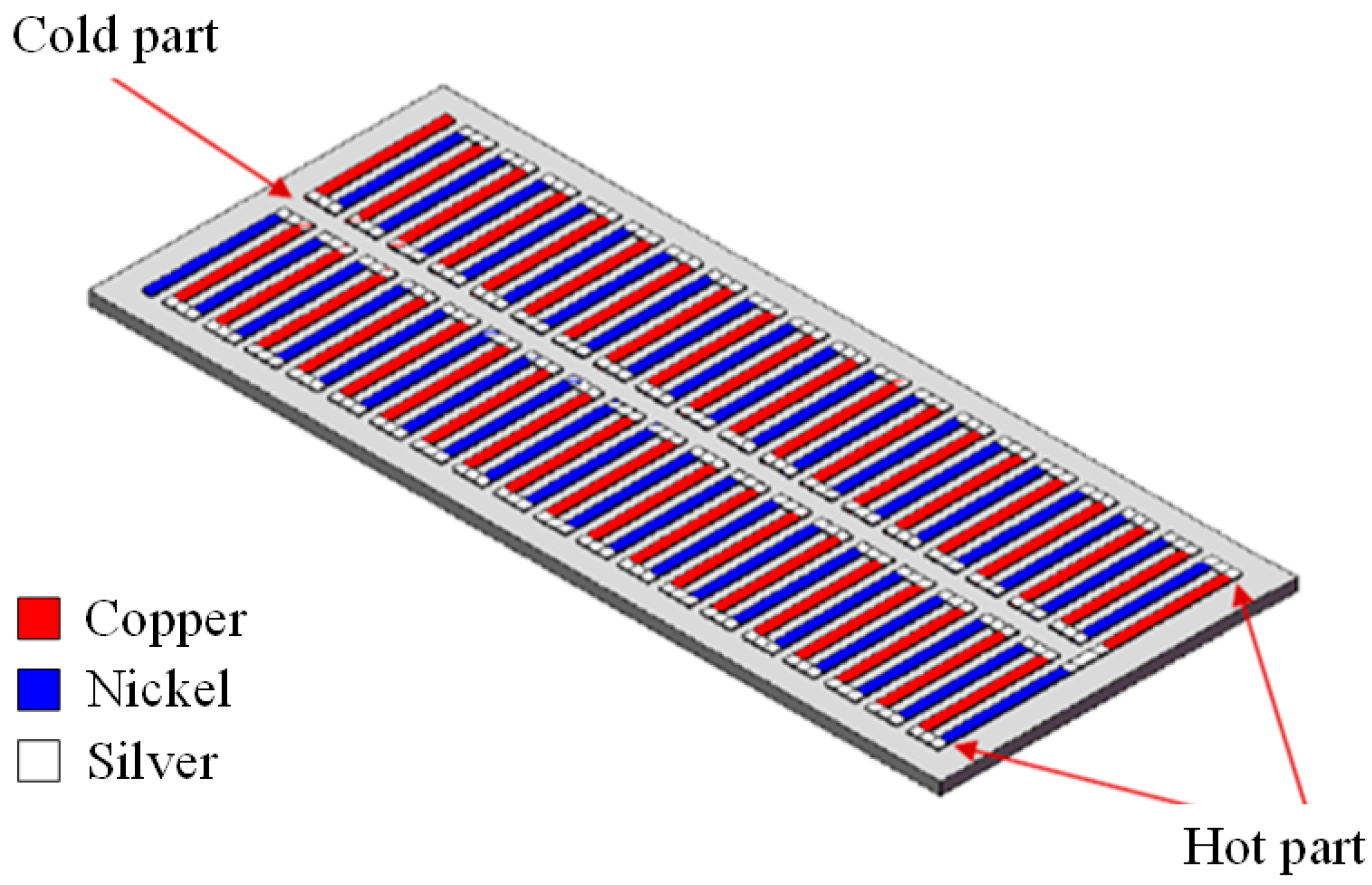
Figure 2.
Simulated output voltage for the flexible thermoelectric generator.
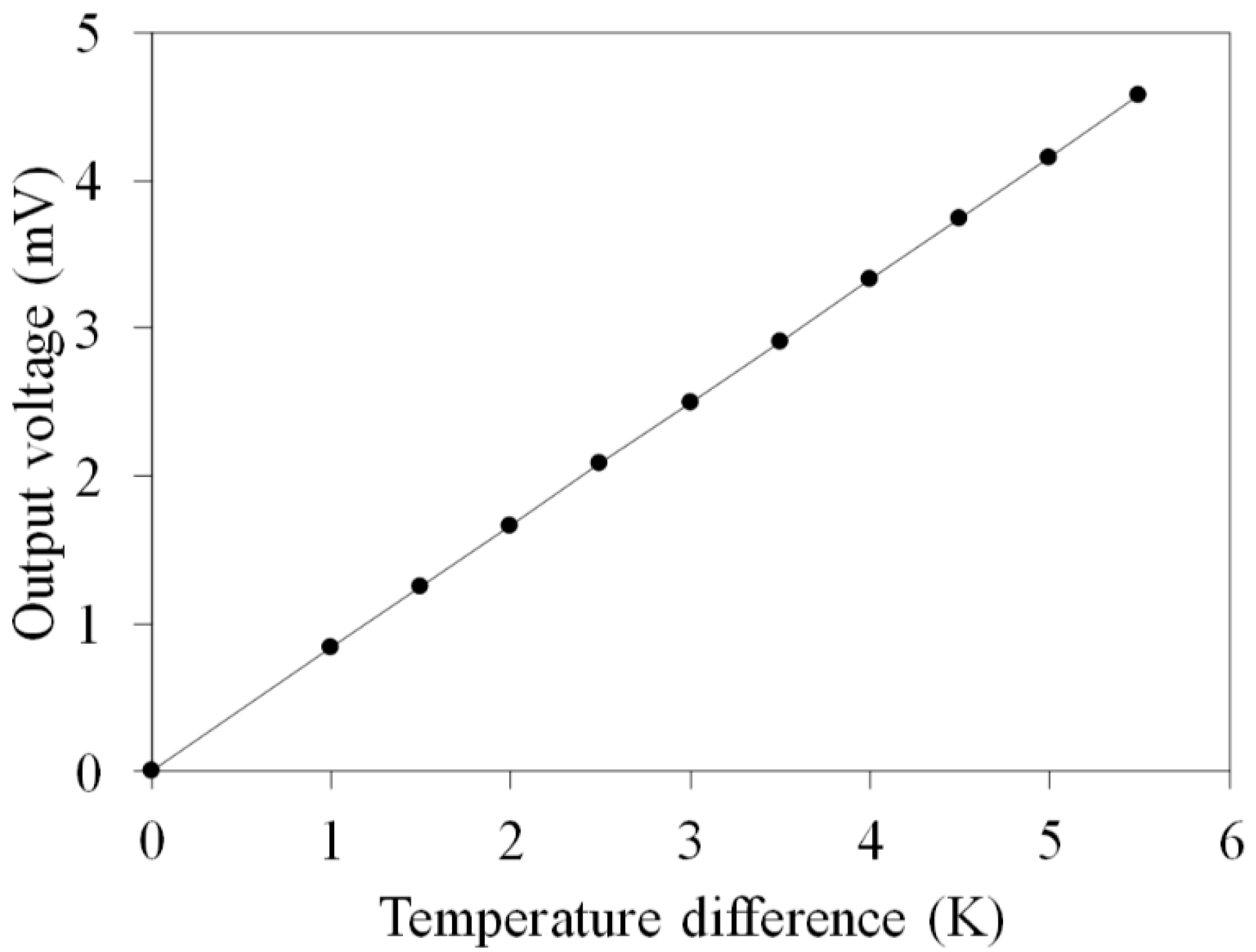
Figure 3.
Simulated output power for a flexible thermoelectric generator.

Figure 4.
Process flow for a flexible thermoelectric generator: (a) Defining a silver seed layer; (b) electroplating copper; (c) electroplating nickel; (d) coating epoxy polymer; (e) etching polymethyl methacrylate substrate; (f) painting silver; (g) packaging.
Figure 4.
Process flow for a flexible thermoelectric generator: (a) Defining a silver seed layer; (b) electroplating copper; (c) electroplating nickel; (d) coating epoxy polymer; (e) etching polymethyl methacrylate substrate; (f) painting silver; (g) packaging.
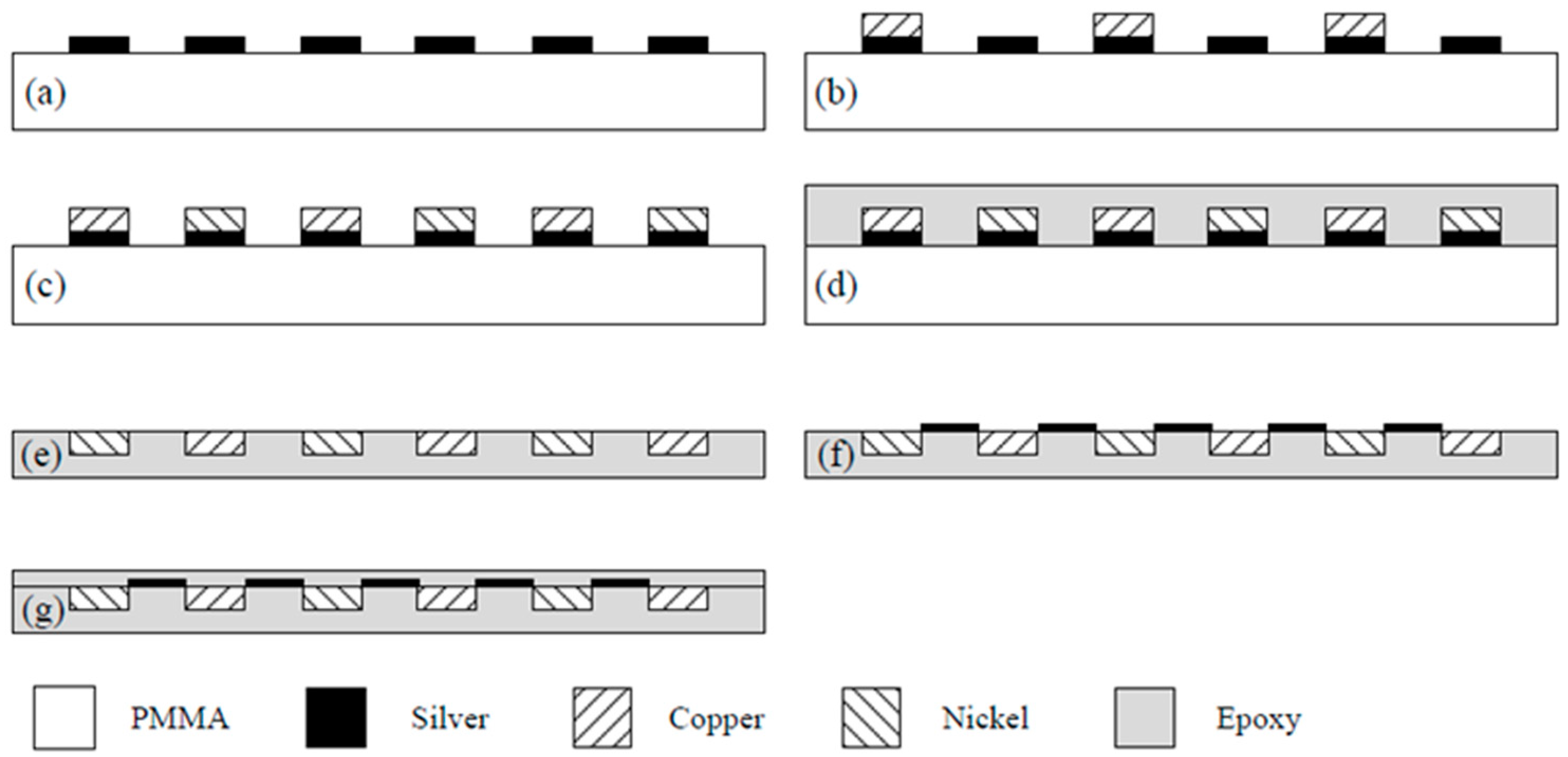
Figure 5.
The pattern of the silver seed layer.

Figure 6.
An image of the flexible thermoelectric generator.
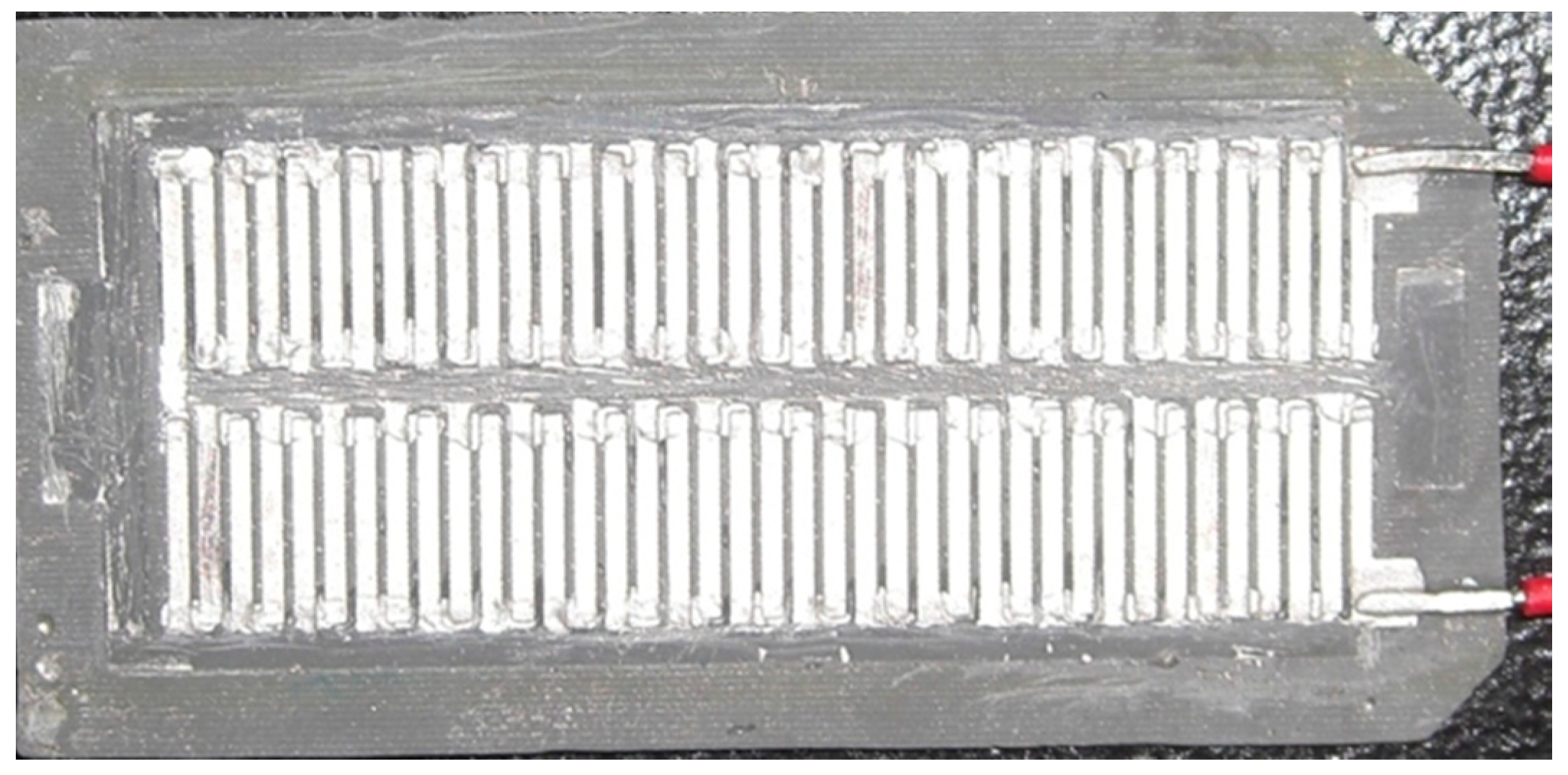
Figure 7.
Demonstration of the flexibility of the flexible thermoelectric generator.
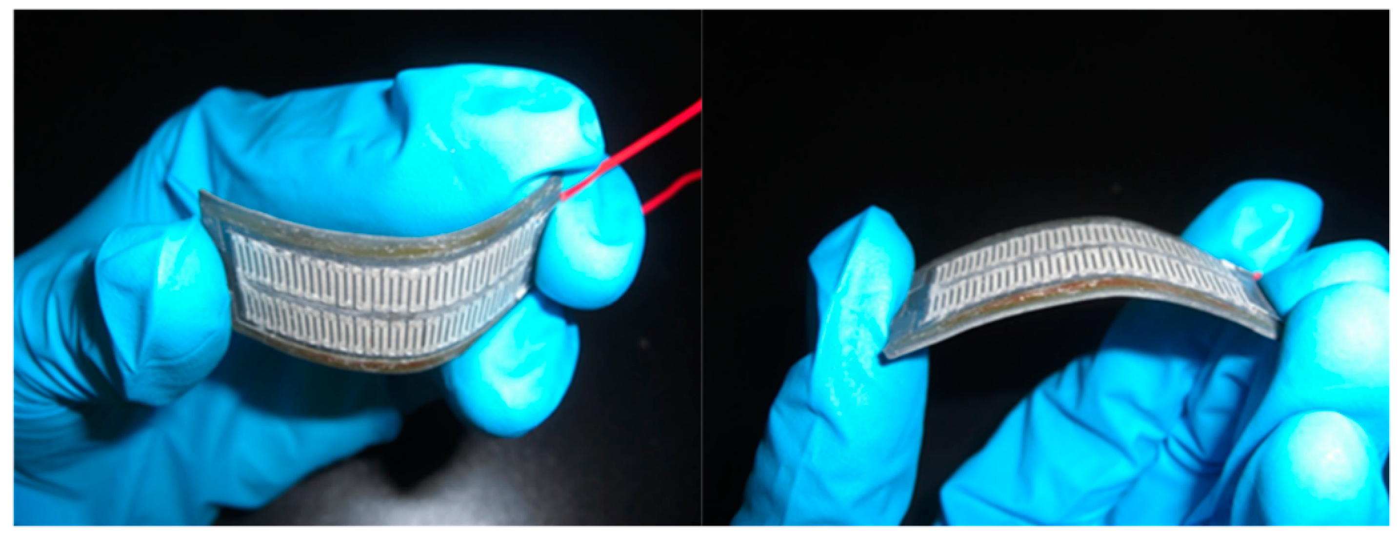
Figure 8.
Measurements for the output voltage of the flexible thermoelectric generator.

Figure 9.
Measurements for the output power of the flexible thermoelectric generator.
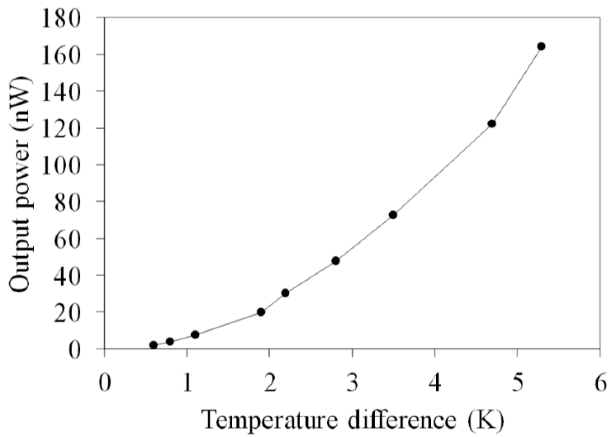
Figure 10.
Output voltage of the flexible thermoelectric generator at different current density.
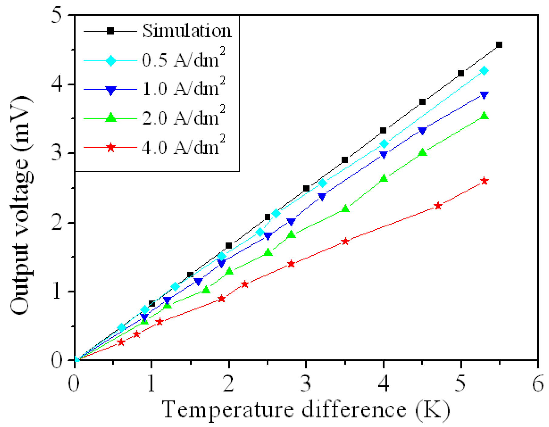
Figure 11.
Output power of the flexible thermoelectric generator at different current density.
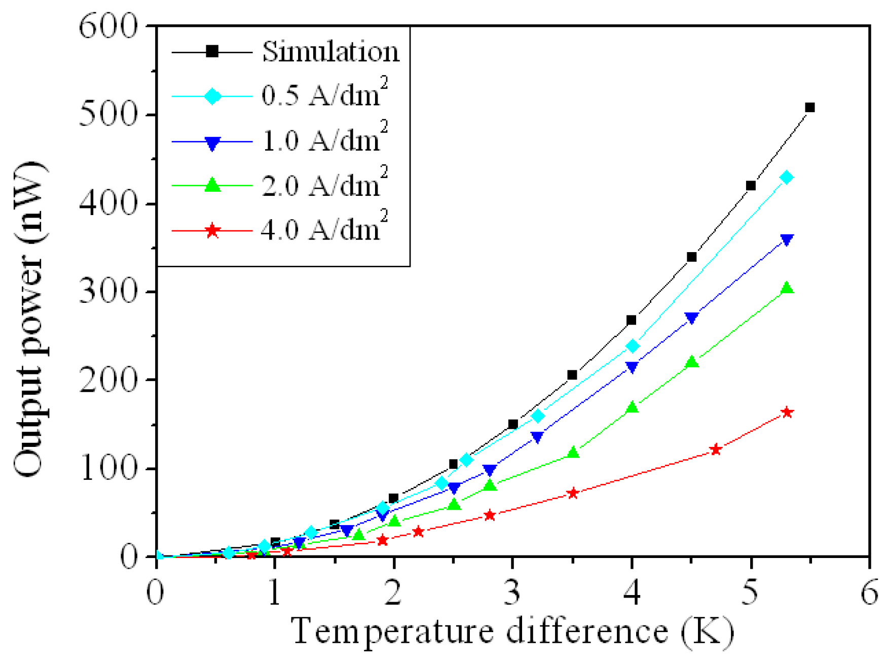
Figure 12.
Relationship between resistance and curvature for the FTG.


© 2019 by the authors. Licensee MDPI, Basel, Switzerland. This article is an open access article distributed under the terms and conditions of the Creative Commons Attribution (CC BY) license (http://creativecommons.org/licenses/by/4.0/).
Share and Cite
MDPI and ACS Style
Lee, W.-L.; Shih, P.-J.; Hsu, C.-C.; Dai, C.-L. Fabrication and Characterization of Flexible Thermoelectric Generators Using Micromachining and Electroplating Techniques. Micromachines 2019, 10, 660. https://doi.org/10.3390/mi10100660
AMA Style
Lee W-L, Shih P-J, Hsu C-C, Dai C-L. Fabrication and Characterization of Flexible Thermoelectric Generators Using Micromachining and Electroplating Techniques. Micromachines. 2019; 10(10):660. https://doi.org/10.3390/mi10100660
Chicago/Turabian StyleLee, Wnag-Lin, Po-Jen Shih, Cheng-Chih Hsu, and Ching-Liang Dai. 2019. "Fabrication and Characterization of Flexible Thermoelectric Generators Using Micromachining and Electroplating Techniques" Micromachines 10, no. 10: 660. https://doi.org/10.3390/mi10100660
Note that from the first issue of 2016, this journal uses article numbers instead of page numbers. See further details here.