1. Introduction
As has been happening in other countries for several years [
1,
2,
3,
4,
5,
6,
7,
8,
9,
10], in Italy too, there is now a renewed interest in raw-earth constructions (see for example: the Italian bill dated 14/02/2002 titled “Normative to support raw-earth buildings and raw-earth as a building material”). Raw-earth constructions are, in fact, environmentally-friendly and highly bio-sustainable. Their very low environmental impact is thanks to the little energy needed during the building stage and the thorough recyclability of almost all of their building materials, which are often completely natural and compatible [
5]. In addition, raw-earth constructions perform well thermally [
11,
12,
13,
14,
15,
16,
17]; allowing the buildings good thermal insulation capacities and thermo-hygrometric comfort of the indoor environments, including sound insulation [
18]. In this way, raw-earth constructions have been encouraged during recent years, especially in those countries where they could be an easily accessible and economically attractive resource due to the climatic and economic conditions, , joining well to the local traditional architecture.
Moreover, thanks to the diffusion of a new receptivity, the old historical earthen architectures begin to be no longer seen as poor constructions inherited from the past or as obstacles and menaces to new settlements and productive investments, but this cultural heritage is perceived as being the face of a local identity and as a possible way of development. This new sensibility—embraced also by designers and Cultural Heritage offices—is spreading towards a working philosophy that considers architectural assets not only for historic-artistic value but also a testimony of an antique art of building that must be understood and not refused, so the concept of conservation should also be extended to building techniques. Nevertheless, at least in Italy, the prejudice with which these buildings were often regarded has resulted in a completely negative attitude to their restoration and reuse up until now. Thus, today only a small amount of these buildings are left, because of the gradual abandonment of the remains and the consequent reuse of their recyclable parts. As a result, the remaining examples must be urgently safeguarded and compatible uses must be sought to promote their regular maintenance. Raw-earth architectures are, in fact, particularly subject to natural degradation (especially by weathering, since there are frequently no protective elements such as gutters, and in some cases whole roof sections have collapsed due to neglect) and they have been estimated to have a life of some 60 years without maintenance [
19]. In response to the initial stimulus of regional funds and laws (see for example: Marche Regional Law no. 6 of 24/03/1998), some Italian regions, like the Marche region, have started to develop a policy for restoring earth buildings (see for example: Marche Rural Development Plan 2000/06), promoting their protection and conservation, and their organization into buildings suitable for new use.
However, one must face the problem that it is usually unknown how to make repairs and reuse the building technique at an affordable cost. To a certain extent, this is caused by the lack of skilled masons and because engineers and architects are used to ignore earth as a building material. Thus, designers are not able to understand how an earthen building works, and such difficulties can often lead to wrong planning decisions. It is easy to find incorrect repairs, such as the typical cement-rich renders covering raw-earth walls [
5]. These renders are too stiff to adapt to natural wall movements, so they easily crack, allowing rain water to enter and to become trapped inside the wall due to the low porosity of the rendering. The use of earth- or lime-based renders would be more appropriate. Moreover, there is a strong need to assess earthen building mechanical properties in order to guarantee an adequate structural safety, especially for some local earthen building techniques such as cob, that has been studied less than, for example, adobe.
To this end, the following paragraphs report the first results of a research that has dealt with an Italian traditional cob technique used for the construction of historical earthen buildings present in Macerata (Italy), just to regain possession of the material and constructional aspects, namely the so-called workmanlike [
20], and their initial structural resources, in order to give guidelines to improve the technology for its reuse in new earthen constructions or to accurately work on these historical earthen buildings for their compatible and sustainable conservation.
The Case Study: Historical Cob Constructions in Macerata
The historical cob earthen buildings in Macerata are the starting point of this research. A full quarter, called “Villa Ficana”, near the northern neighborhood of Macerata, was built during the 19th century not far away from the city center and had earthen walls in many of its houses. This is one of few examples of a whole intact raw earth workers’ village which has remained with us up until now.
The Ministry for the Cultural Heritage recently declared this earthen quarter deserving of protection pursuant to the Legislative Decree no. 490/99, considering the absolutely exceptional nature of the area. This guarantees the full conservation of every element of it, recognizing the compound, composed by various buildings, roads, open spaces, gardens, to be of particular historical and documentary importance, insofar as it is material evidence of:
a pre-urban peasant culture typical of the 19th century;
an ancient construction technique, capable of creating buildings with natural materials not derived from production processes outside the building site itself, that has by now completely disappeared;
an urban layout that is unique in its type and as a whole.
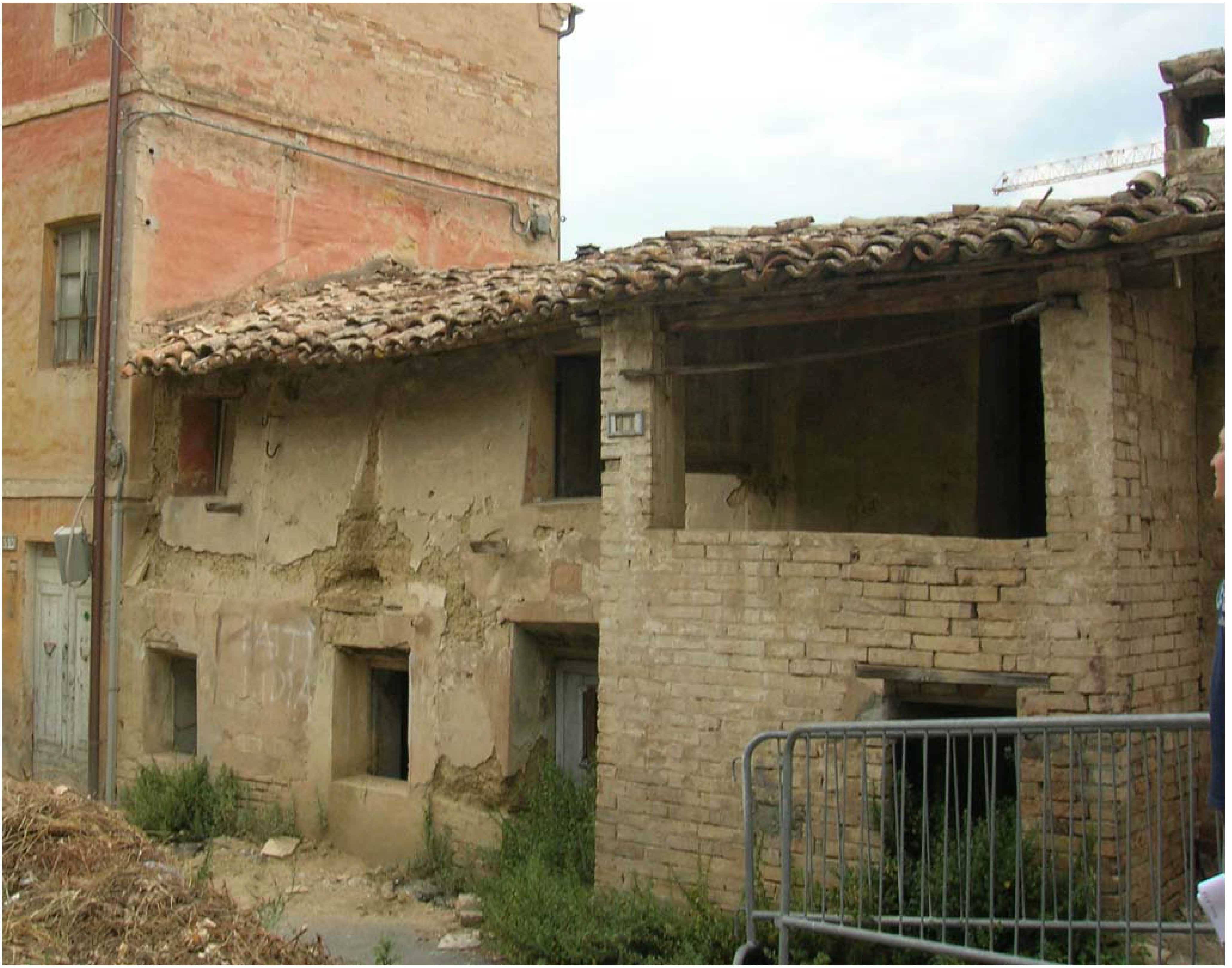
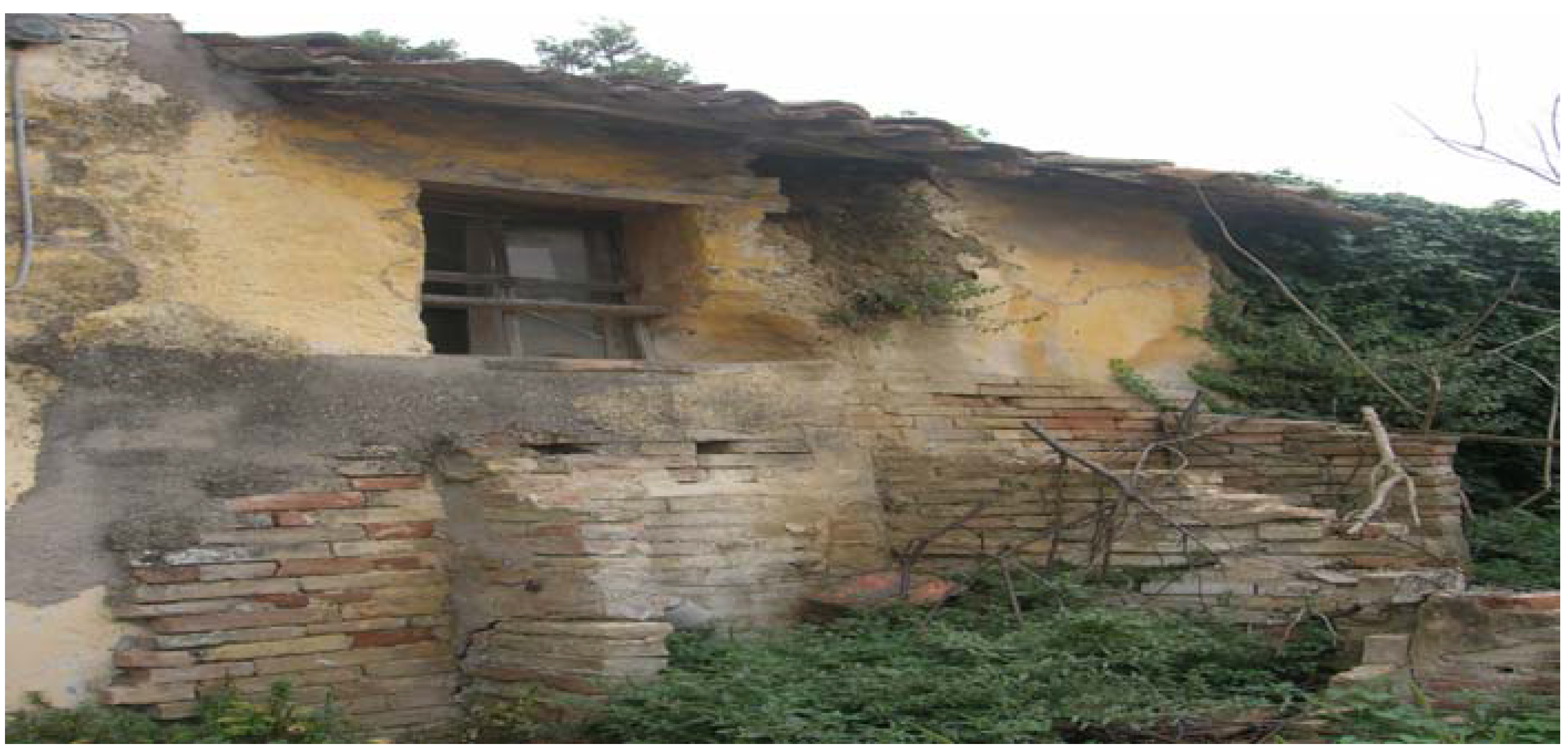
In any case, almost all the houses have been abandoned by their owners and have been particularly subjected to weathering since there are often no protective elements such as guttering left (
Figure 1). There are many reasons why these houses were abandoned, but most commonly this is because the idea of poverty and marginalization has always been associated with this type of housing in this geographical area.
The common typology of these houses is two floors with a generally external masonry stair (
Figure 2). The floor system is composed of a series of timber beams and joists covered with a layer of tile elements. The roof, covered by tile elements, is sloped, usually with the presence of a primary and secondary timber beams. The eaves have a length up to 0.40–0.50 m to protect the walls from rain.
Figure 1.
An example of a neglected raw-earth cob building in Macerata (Italy). The erosion by weathering due to the lack of the roof protection can be seen.
Figure 1.
An example of a neglected raw-earth cob building in Macerata (Italy). The erosion by weathering due to the lack of the roof protection can be seen.
Figure 2.
Typical raw-earth cob architecture at “Villa Ficana” in Macerata (Italy). An external masonry staircase is often present to connect the two levels of the house. A masonry support is also visible low on the left.
Figure 2.
Typical raw-earth cob architecture at “Villa Ficana” in Macerata (Italy). An external masonry staircase is often present to connect the two levels of the house. A masonry support is also visible low on the left.
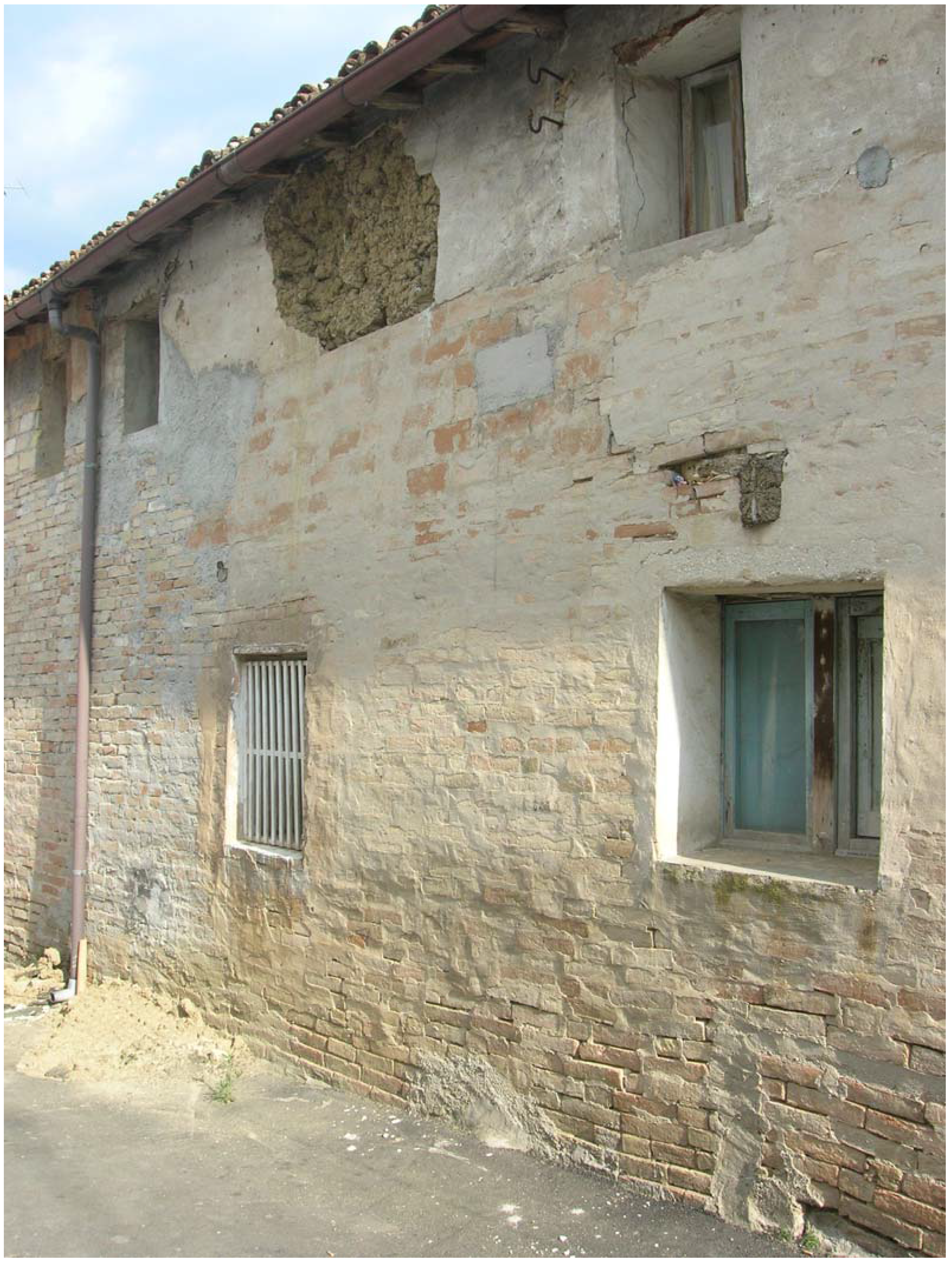
The thickness of the earthen walls is about 1–1.10 m on the ground floor and from 0.60 to 1.10 m on the first floor, and the windows are small in order to reduce heat dispersion and water infiltration. In some houses there are also walls made by fired bricks. Several earthen walls were built above a masonry base which has a height of about 0.40–0.50 m. This allowed the wall to resist excessive vulnerability with respect to ground surface erosion and water absorption. Earthen wall external surfaces are sometimes safeguarded by a 0.05–0.10 m earthen plaster or a common vertical brick layer (
Figure 3).
Figure 3.
Raw-earth cob walls are often safeguarded by a thick earthen plaster or by a layer of fired bricks.
Figure 3.
Raw-earth cob walls are often safeguarded by a thick earthen plaster or by a layer of fired bricks.
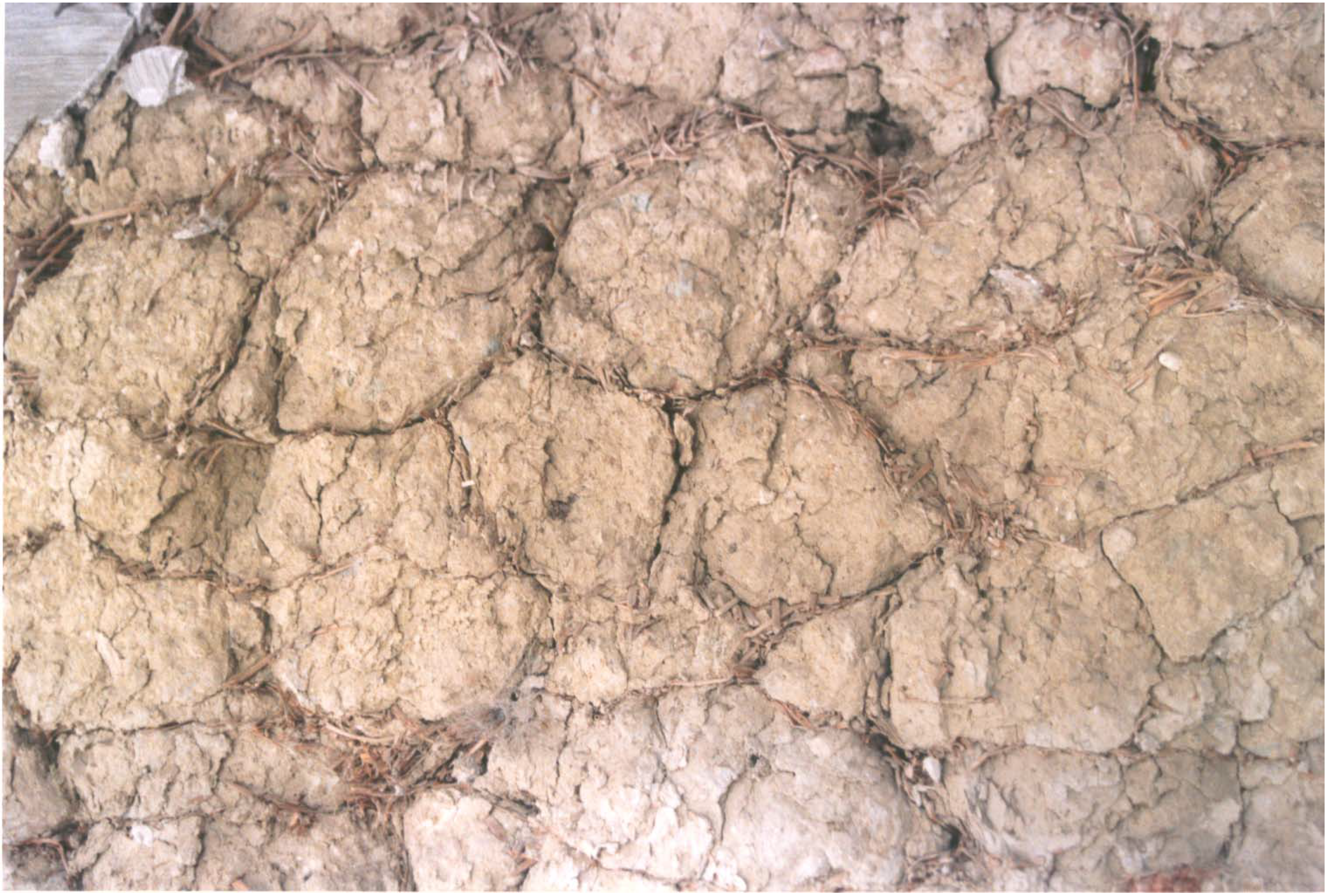
Processing the acquired data during accurate surveys and subsequently by laboratory analysis carried out on these earth buildings, it was possible to identify—as first results—the technique used to construct the earthen walls. The technique is similar to the one commonly called “bauge” in France or “cob” in the United Kingdom. Large cylinder-shaped “bricks” (cob bricks) can be in fact easily recognized (
Figure 4). They are more or less compressed due to the construction of the wall which bears its own weight. Each base element, or cob brick, is called “massone” in jargon by local inhabitants.
Figure 4.
An external wall reveals the presence of cob bricks covered by straw.
Figure 4.
An external wall reveals the presence of cob bricks covered by straw.
Comparing results from soil composition and limits of consistency (Atterberg’s limits) of earth samples taken from the buildings, the soil used as a construction material directly came from the construction site, as expected. It is clearly not topsoil, which is unsuitable due mainly to the significant amount of organic matter present that biodegrades, absorbs water, and is highly compressible. It has the texture [
21], and the limits of consistency [
22] reported in
Table 1. As a building material, its water content ranged from 6 to 10%, with a dry specific density equal to 1,860 kg/m
3. No straw was found in the core of the taken samples, but was only on the external surface, probably to limit the considerable shrinkage of the material [
4]. Straw, in fact, can reduce hygrometric shrinkage because of both its tensile strength and, above all, its slow water release capability [
3].
The onsite soil was probably moistened and trod on by human feet in shallow pits. Subsequently, it was shaped into large cylinders (cob bricks) of 0.08 to 0.15 m in diameter to a depth of 0.30–0.40 m, which were rolled and covered by straw. These were then thrown up to a bricklayer who stood on a finished part of the wall under construction and formed the new layer of cob by throwing the still moist cylinders forcefully and rhythmically onto the wall up to a height of about 0.50–0.70 m. The wall under construction was then left to dry for some days, then the successive level could be constructed. In this way, very thick walls (0.60 to 1.10 m) consisting of several layers of monolithic appearance could be built.
2. Materials and Methods
Experimental tests were performed. They were firstly aimed at the possibility of reproducing the old technique, using first the onsite soil and then an earth of analogous composition, in order to regain possession of the constructional aspects, namely the so-called workmanship, to characterize a suitable soil for possible restoring intervention, and to improve, if possible, the same technique in the light of our modern technology.
Then, seven cob walls were built to test by compression. Compressive strength is, in fact, the most important parameter for earthen materials, just like for any unreinforced masonry. It enables not only the quality control of a material, but especially represents a means to assess and compare the material’s performance [
1]. In this case, the aim was to evaluate the
initial compressive strength; that is the compressive strength when the first elevation of a cob earthen wall is completed, when cob bricks are still moist and the seasoning not finished. This can allow one to assess how re-using this building technique—both for new constructions, and possibly for restoring intervention or new additions—optimizes time and costs.
Five samples were also tested by shear. The shear strength is, in fact, an important parameter when two materials are coupled and their relative movements are driven by friction and/or cohesion. Even in this case, we aimed at assessing the initial shear strength, which is the shear strength that could exist along the interface between the dried existing earthen cob walls and the newly added, moist cob bricks. This can allow evaluation of possible restoring intervention such as for repairing a crack or super-elevating an existing cob earthen wall.
2.1. Manufacturing Process for Hand-Made Cob Bricks
Initially, the onsite soil was used to produce each earthen base element (cob brick or “massone” in Italian jargon). This enabled the authors to reproduce and to regain possession of the ancient building technique.
Starting from a water content of the onsite soil of about 6%, it was decided to add molding water so to exceed the plastic limit of about 5–10% in order to have a workable mixture, but not to add too much water such that it would be a negative parameter for compressive strength [
4]. Thus, an average mass of 3 kg of soil and of 0.6 kg of water mixed together were needed to produce a single cob brick of 0.08–0.10 m in diameter and a length of about 0.35 m. Straw was added by rolling and pushing each sample on a straw-bed. It was cut in fibers with a length of about 50–100 mm and it was wetted before being used, so that it would not absorb water from the earthen samples. An average weight of 0.2 N of straw usually remained on the external surface of each sample.
It took about 4–5 minutes to hand-make a single cob brick.
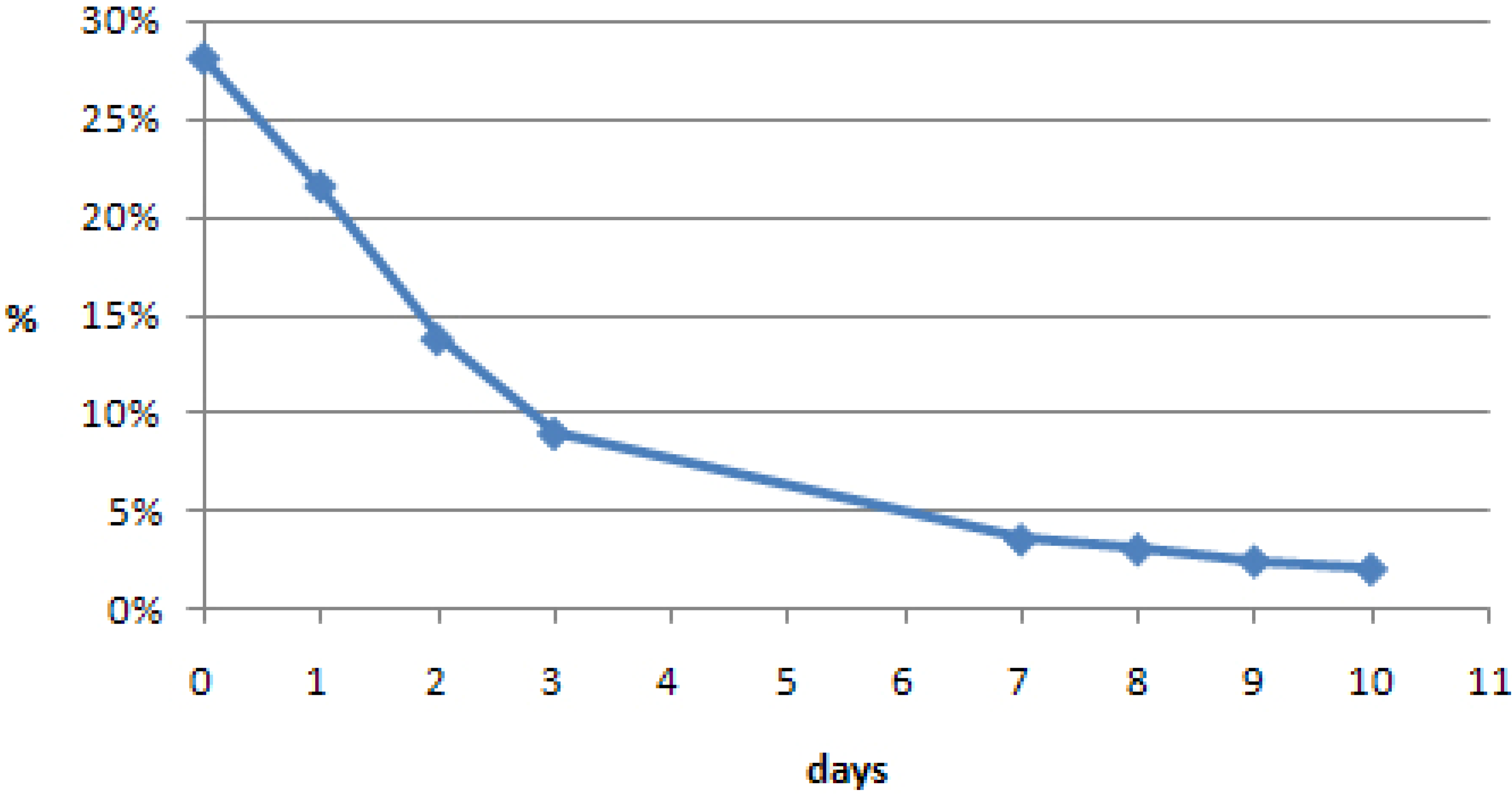
An average water content of about 28% was found for each cob brick at the end. This is in total agreement with other previous studies [
1].
Figure 5 reports a typical drying curve for a cob brick at a constant temperature (T) of 30 ºC and a maximum relative humidity (RH) of 30%. It is worth noting that after about a day, each cob brick reached, on average, a water content lower than its plastic limit, and after about a week its water content was similar to those found on the earthen walls
in situ. No samples cracked during the drying process.
Figure 5.
Typical drying curve for a cob brick at a temperature (T) = 30 ºC and maximum relative humidity (RH) ≈ 30%. % water content is shown over time.
Figure 5.
Typical drying curve for a cob brick at a temperature (T) = 30 ºC and maximum relative humidity (RH) ≈ 30%. % water content is shown over time.
Due to its urbanization, it was impossible to use soil coming from Villa Ficana to make a large number of cob bricks. Thus, it was decided to find a compatible soil near Villa Ficana, both for the experimental characterization of the building technique and for possible future restoring works and new constructions. Places close to Macerata were considered in order to more easily detect a soil similar to the in situ one and to reduce transportation costs if used for future restoration interventions.
A soil used to produce fired bricks about 8 km from Villa Ficana was chosen. It came from a local quarry and it was very similar to that used for the Villa Ficana earthen walls. It was called “yellow soil” because of its color, in order to distinguish it from the original one.
Table 1 compares their composition and Atterberg’s limits.
The same procedure as described above was performed to hand-make some cob bricks in order to assess the workability of the yellow soil. The only difference was in the initial soil water content, which was about 4.75% for the yellow soil, thus it was necessary to add more molding water (8 N).
No differences were found during the manufacturing process.
Table 1.
Average composition of the two soil analyzed and their liquid limits and plastic indices.
Table 1.
Average composition of the two soil analyzed and their liquid limits and plastic indices.
| | Clay (%) | Sand (%) | Silt (%) | Liquid limit (%) | Plastic index (%) |
|---|
| Original soil | 34 | 17 | 49 | 38 | 19 |
| Yellow soil | 36 | 13.5 | 50.5 | 42 | 21 |
2.2. Mechanical Manufacturing Procedures and Assembly of Cob Walls
To accelerate the production of the base elements and to reduce costs for future possible restoring interventions and new constructions, it was decided to change the soil-water mixture manufacturing procedure to instead use a mechanical mixing machine, commonly used in the manufacturing of fired clay bricks. The mechanical mixing machine blended the selected yellow soil with molding water until reaching an average water content of 35%, in good agreement with previous studies [
1]. Each cob brick, instead, continued to be shaped by hand, thanks to a skilled mason, into large cylinders 0.08 to 0.15 m in diameter and 0.30–0.40 m in depth, which were subsequently covered by straw, as before.
No significant differences were found when comparing the completely hand-made cob bricks and the partially mechanically-made cob bricks. It took significantly less time to manufacture each partially mechanically-made cob brick (about 2 minutes).
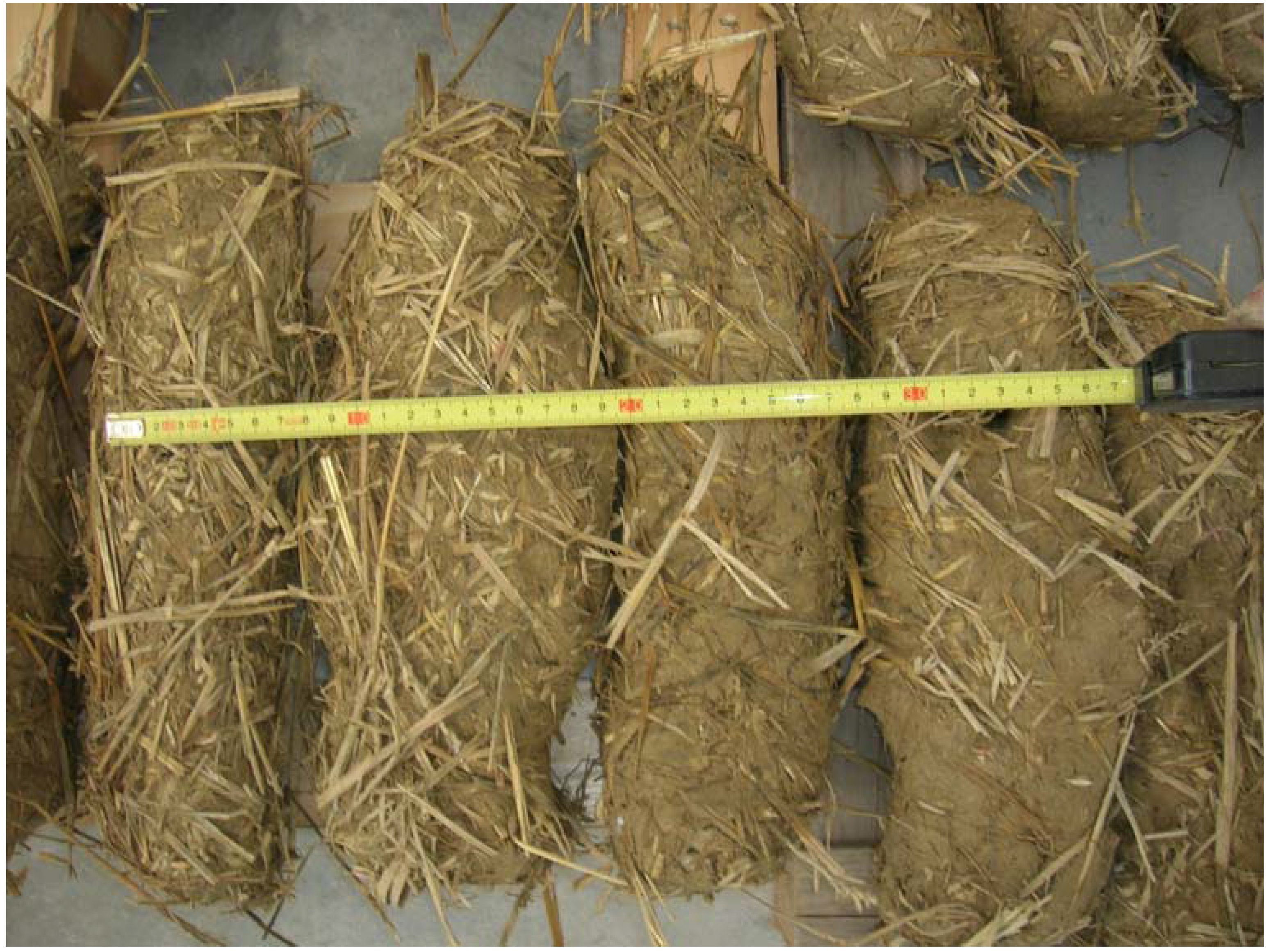
In this way, about 210 cob bricks were manufactured (
Figure 6) and seven earthen walls were made.
Each earthen wall was made by throwing each moistened cob brick forcefully layer upon layer, up to five layers. Each layer was manufactured by six cob bricks, for a total of 30 cob bricks for each earthen wall. Each cob brick was placed immediately adjacent to another with the longest side (about 0.35 m) along the wall thickness, creating staggered joints between each layer (as in the original case). No layer of mortar was included. The nominal dimensions of each wall were 0.60 × 0.35 × 0.30 m
3 (
Figure 7). Each wall was then left to dry for about a month and a half, which is about the time spent to build a single-storey cob earthen wall, at an average T = 24–26 ºC and an average RH = 63–66% for approximately the first half, and an average RH = 47% for the rest, in order to abruptly simulate a spring or an early autumn season when earthen cob houses were usually built.
Figure 6.
Some cob bricks made by yellow soil.
Figure 6.
Some cob bricks made by yellow soil.
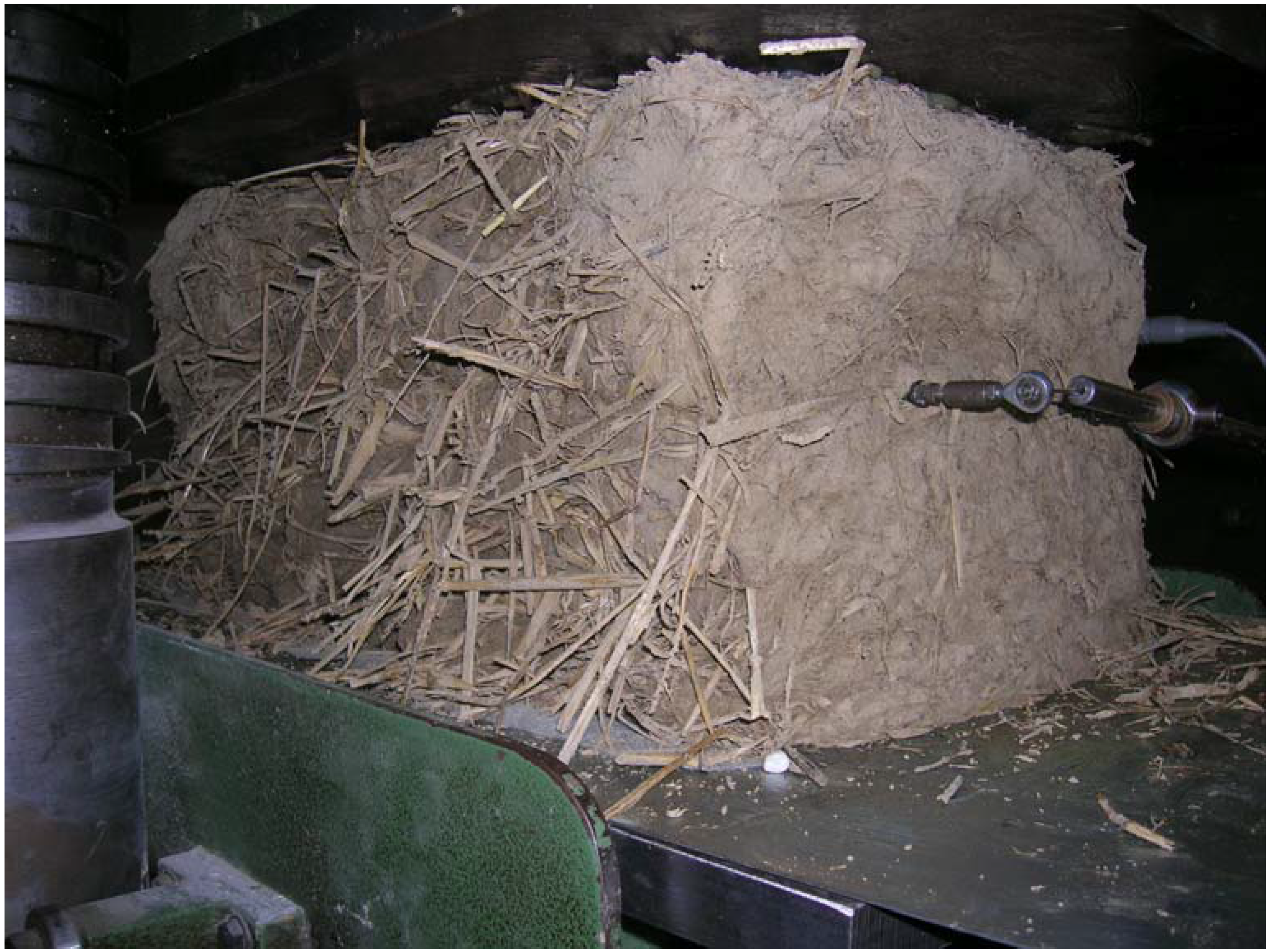
Figure 7.
A raw-earth cob sample tested by uniaxial compression.
Figure 7.
A raw-earth cob sample tested by uniaxial compression.
2.3. Compression Testing Procedure
Compression tests were set to allow uniform distribution of stresses on specimens. For this purpose, each specimen was inserted between a lower and an upper steel plate sprinkled by fat in order to reduce friction. All the samples were tested along the direction they generally withstood loads. The apparatus used for the compression tests was a first class “Metrocom MI 300” with a 1% error and with an end scale of 3,000 kN. It had two transducers: one for pressure and one for vertical displacement.
The results of the first cob wall tested (specimen 1) was only considered to check the trial, thus they are not reported in the following. In any case, they suggested that a pre-load of 5–10 kN (≈ 3−5.5 × 10
−2 MPa) should be applied to each wall to assess the intrinsic behavior of the material and to minimize the measure of the contact adjustment phase related to the fact that the surface sample is not perfectly plane, due to the asperities of the wall surfaces always present and due also to the shrinkage that occurs during the drying process, which is not perfectly uniform [
1].
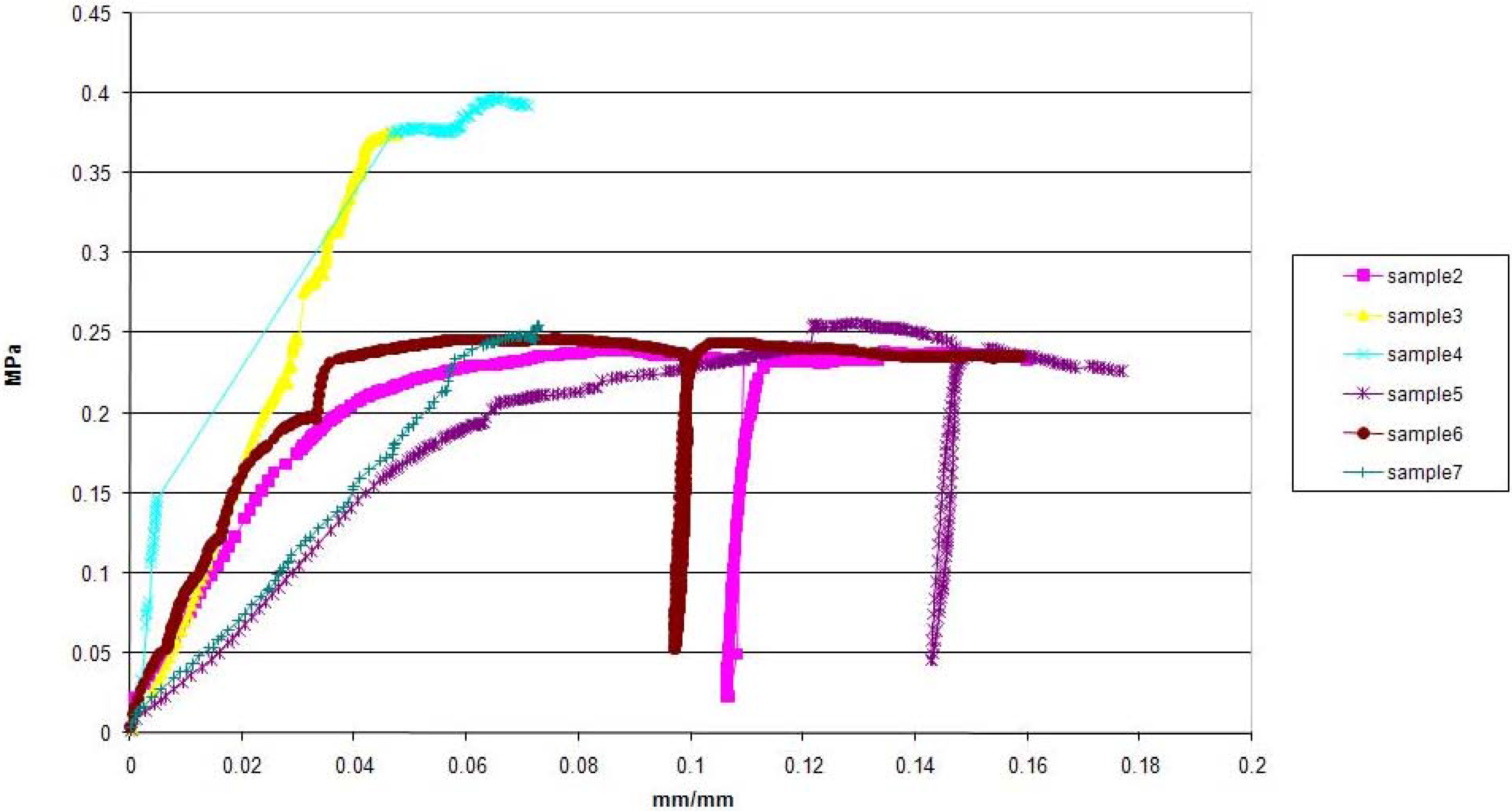
Three samples were also unloaded and then reloaded, when they reached a strain εunld with 1.10εσmax ≤ εunld ≤ 1.15εσmax (wall 5) and 1.25εσmax ≤ εunld ≤ 1.30εσmax (wall 2 and 6), where εσmax is the strain related to the maximum compression stress.
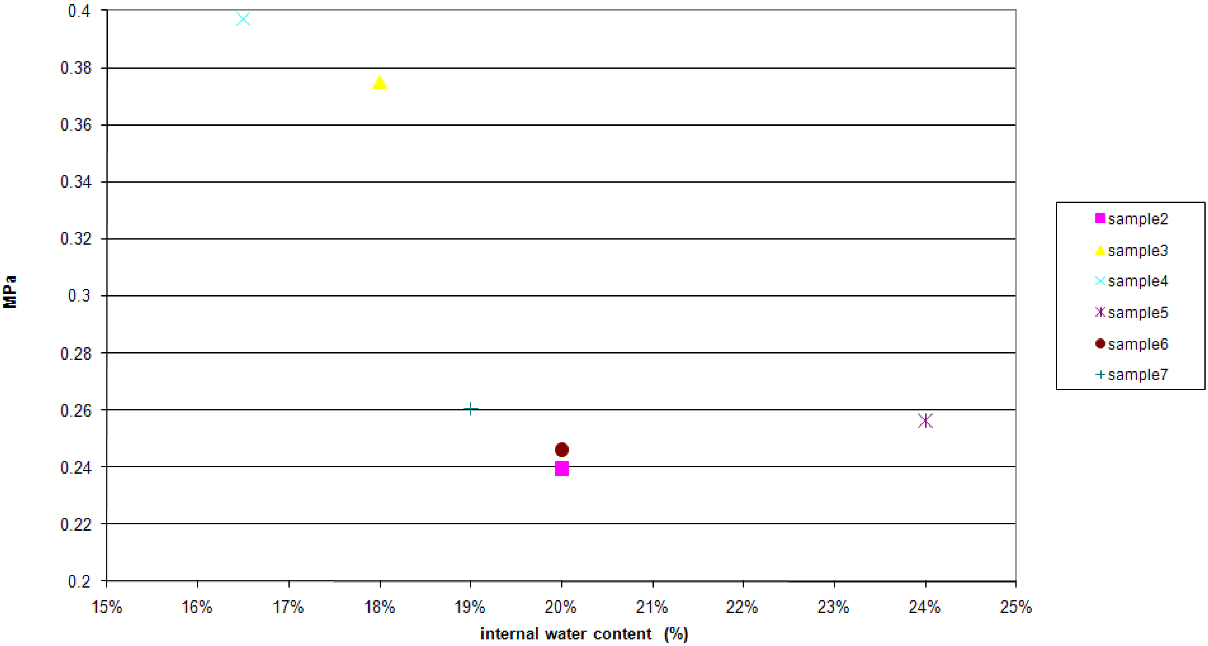
Compression stresses were obtained by dividing the net force by the area of the specimen (i.e., by considering the average or nominal stress), while the initial compressive strength was calculated as the average of the first cycle maximum compression stress of each specimen.
At the end of each compression test, two specimens were sampled: one on the external surface of the wall and another one in the core. These specimens were used for the determination of the external and internal water content of each wall, respectively.
2.4. Shear Testing Procedure
Five specimens were tested under shear. A classical Casagrande apparatus was used [
23], thus each specimen was made by yellow soil with an initial water content similar to that of the previous cob bricks and had the following dimensions: 0.06 × 0.06 × 0.22 m
3.
No straw was added because of the small specimen dimensions.
Three specimens were tested by shear after seasoning with a water content of about 4−6%, as for the onsite earthen walls, at three different constant compression stresses. They were called DD-samples.
Two of these three samples were tested by shear again at different constant compression stresses, by substituting the “yellow soil” enclosed into the upper part of the Casagrande box with yellow soil at a greater water content (≈33%). In this way, these two samples were both made by two different portions of the same soil but at different water contents. They were called WD-samples.
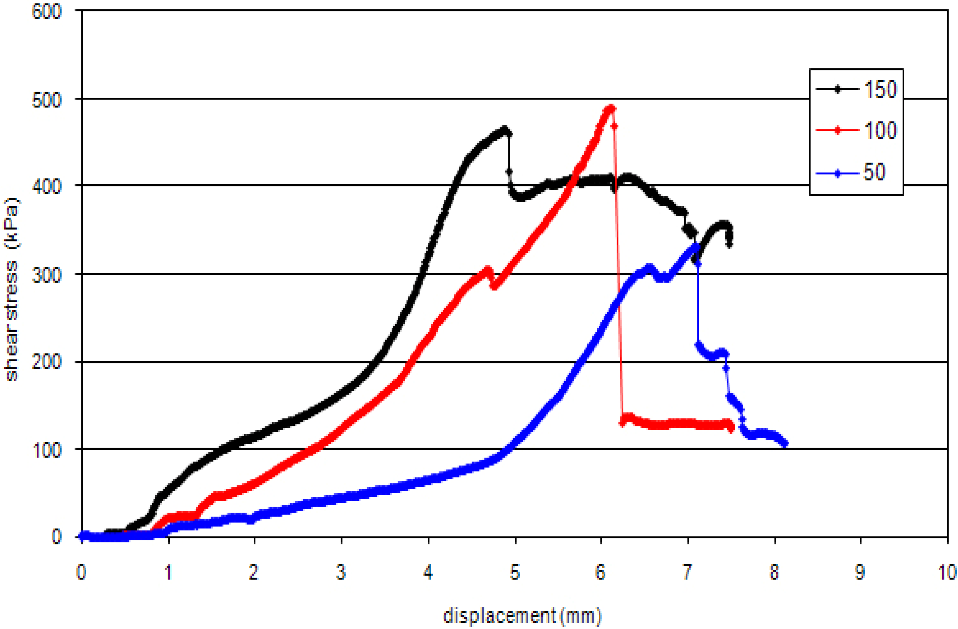
Table 2 reports the test conditions for each sample. The applied horizontal displacement rate was set to 1.46 × 10
−3 mm/min. The shear phase started after 24 hours since the constant compression value had been applied.
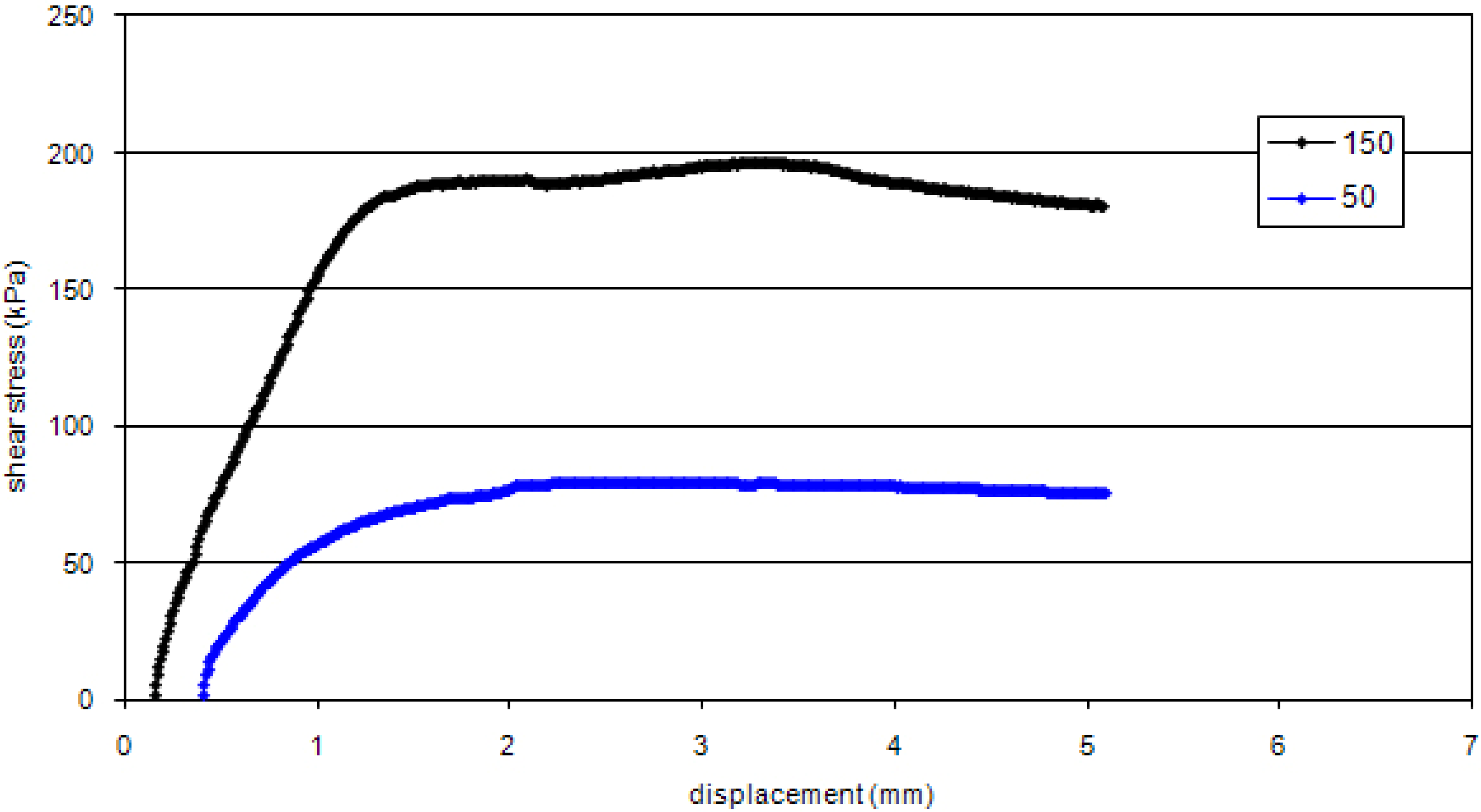
The tangential tensions τ were obtained by dividing the net force by the area of the specimen (i.e., by considering the average or nominal stress), while the initial shear strength was assumed as the maximum shear stress of each sample.
Table 2.
The vertical compression stresses applied on each sample during the shear test.
Table 2.
The vertical compression stresses applied on each sample during the shear test.
| | Vertical compression stress [kPa] |
|---|
| DD-sample 1 | 50 |
| DD-sample 2 | 100 |
| DD-sample 3 | 150 |
| WD-sample 1 | 50 |
| WD-sample 2 | 150 |
2.5. The Assessment of the Building Cost
In order to estimate the cob masonry unitary price per m
3 we considered the unitary cost of various production factors and their quantity. In general, we defined the unitary price of a phase as the sum of the following terms:
cost of materials (earth, coarse sand, straw fibers);
cost of upload, transport and download of materials;
cost of the manpower;
cost of eventual technical equipment;
general costs for the initial preparation of the building area, which was considered equal to 10% of the sum of materials and manpower costs;
establishment profit, which was considered equal to 15% of the sum of the costs of materials, manpower and of the general costs.
To estimate the quantity of materials used to realize a single cob brick, the time of the manufacturing process and the others production factors employed in the construction of the cob masonries, we used what was inferred by the experimental campaign (partially mechanically-made cob bricks), and the list of unitary prices with reference to our local market for the building production factors.
4. Conclusions
Raw-earthen buildings can be considered sustainable buildings, because of their very small environmental impact, their good thermal and hygrometric performances, their sound insulation, and their potential cheapness. They also represent a cultural architectural heritage that shows the face of a local identity and that is also a testimony of an antique art of building that must be preserved.
In this way, the present research tries to regain possession of the constructional aspects of an Italian traditional cob technique and to provide some mechanical resources for its potential reuse, improving its technology, both for building new earthen masonries and making compatible restoration works on surviving architectures at affordable costs.
In this way, the following general conclusions emerge from this study on historic earth cob architectures in Macerata (Italy):
The traditional cob manufacturing process can be improved by using a mechanical mixing machine as is commonly used for fired bricks. This could reduce times and costs.
Cob bricks can be immediately used after their manufacturing process to build a single-storey wall even if they are still wet. This is true both for intervening on old cob architectures and for new constructions. However, some traditional rules of art of the old earthen masons should be respected. In particular:
the wall construction should proceed layer by layer, each of no more than 0.50–0.70 m, and then it should be left to dry for some days, after that the successive level can be added;
each cob brick should be forcefully pre-compressed between others, layer after layer, so as to have no aligned joints and to reduce deformations;
The continuity between a dried existing earthen cob wall and the newly added moistened cob bricks, that is for example when a crack is repaired or an existing part of a cob earthen wall is super-elevated, is guaranteed by the high friction coefficient between the two different surfaces. This is generally very important when a horizontal thrust (e.g., during an earthquake) is present and has to be withstood. Even in this case, when, for example, a crack is repaired, the old rule of art saying that it is important that each new wet cob brick is forcefully pre-compressed, layer after layer, is still helpful so as to increase own weight along the discontinuity.
Besides these general rules, the results of this study have also found a suitable soil for future possible compatible restoring intervention on the investigated case study at Macerata, re-using the same ancient building technique, which is the most compatible intervention.


