Abstract
Sustainable transportation is crucial in addressing global road safety and environmental challenges. This study introduces a novel photonic radar system, leveraging Linear Frequency-Modulated Continuous Wave (LFMCW) technology for high-speed data transmission. Operating in a homodyne configuration, this system uses a single oscillator to generate both signal and reference waveforms. It incorporates mode division multiplexing (MDM) to enable the detection and ranging of multiple targets, even under adverse atmospheric conditions. To counter atmospheric attenuation, the system is equipped with a 2 × 2 MIMO technique and an Infinite Impulse Response (IIR) filter. Numerical simulations demonstrate the system’s superior performance in range resolution and target detection, achieving significant power improvements. The IIR filter further enhances detection, achieving a power improvement of 200% for target 1 and 276% for target 2. With low power requirements and enhancement through IIR filter equalization, this system presents a viable option for battery-operated vehicles. This innovative approach offers a low-power high-efficiency solution suitable for battery-operated vehicles, promoting safer and more reliable sustainable transportation.
1. Introduction
Sustainable transportation is a pivotal aspect of modern urban planning, addressing both environmental concerns and road safety. Approximately 1.2 million lives are lost each year globally due to road accidents, placing them among the top causes of mortality []. The rise in accidents has created a substantial demand for advanced technologies in transportation systems. Intelligent Transport Systems (ITSs) are estimated to potentially reduce up to 90% of road fatalities, highlighting the need for their implementation []. By the end of 2027, the ITS market is expected to grow at a rate of 5.8% from its value of 26.68 billion USD in 2019. The goal of ITSs goes beyond enhancing travel convenience and aims to minimize traffic fatalities. Autonomous vehicles are a crucial element of this evolving system as they have the potential to significantly reduce transport-related deaths []. Intelligent vehicles offer numerous benefits by incorporating advanced features such as parking assistance, blind spot monitoring, lane detection, and the ability to detect multiple targets using sensors like radars and cameras. These technologies enhance safety, improve driver assistance, and contribute to a more efficient and reliable transportation experience [,,]. Photonic radar technology stands out as an exceptional method for gathering critical information about the traffic environment. This includes data on speed, altitude, and distance and the capture of images of multiple targets, thereby providing a comprehensive understanding of the surrounding vehicular conditions []. Photonic radar technology uses an optical carrier to transmit modulated radio frequency signals towards a target, and by processing the reflected echoes, the necessary information can be obtained [,,]. It is a promising application for autonomous vehicles as it provides high-speed resolution and precision, making it superior to traditional microwave-based radars.
Nevertheless, atmospheric conditions can adversely affect the performance of photonic radars. Factors such as scattering and absorption by various atmospheric gases and elements can lead to a diminished range resolution, impacting the radar’s effectiveness in accurately gauging distances and detecting objects. Several studies have been conducted to improve the performance of photonic radars in adverse weather conditions, and industries operate in the X-band (8–12 GHz) or S-band, which offers narrow beams for tracking targets and robust immunity against atmospheric turbulences, respectively.
2. Related Work
Photonic radar technology has emerged as a promising solution for high-resolution target detection in various environmental conditions. Previous research has demonstrated the potential of photonic radar systems to achieve superior performance compared to traditional microwave radars. In 2020 [], researchers showcased a photonic radar system capable of detecting drone movement within a range of 2.7 km. Moreover, this technology has the capability to capture real-time images of drones from a considerable distance, specifically up to 1.1 km away. In 2021 [], researchers introduced the innovative concept of microwave photonic radar, a technology designed for accurately detecting the distance and velocity of various targets. This proposed technology achieved a maximum relative error of 2.6% for distance measurements and 0.21% for velocity measurements []. Another work in 2021 [] proposed a photonic-based approach to generate multiple linearly frequency-modulated (LFM) signals using a dual-parallel Mach–Zehnder modulator. The approach generates two single-tone optical sidebands and the 1st and 2nd order optical sidebands of a dual-band LFM signal. In an experiment, eight LFM signals up to 27 GHz in different frequency bands were simultaneously generated, and their performance was verified. Likewise in 2021 [], researchers proposed a photonics system that simultaneously measures the angle of arrival (AOA) and frequency, suppressing undesired frequency mixing and using the Van Cittert–Zernike theorem to estimate AOA from different RF sources. A proof-of-concept experiment successfully measured multiple targets with different frequencies and distinguished incoherent microwave sources.
Atmospheric in-homogeneities such as fog, rain, snow, and dust can significantly impact the performance of photonic radars []. Equalization is a critical signal processing technique used in photonic radars and optical communication systems to improve system performance by compensating for these in-homogeneities []. This process involves adjusting the amplitude and phase of the received signal to mitigate the effects of linear and non-linear distortions caused by various factors. Linear equalization uses a linear filter to correct for linear distortions, while non-linear equalization uses a non-linear filter to correct for non-linear distortions. IIR filters, which have a feedback structure, are commonly used for equalization and noise-filtering tasks in optical communication systems [,]. These filters can compensate for various distortions and filter out noise components while preserving the signal of interest, improving the overall system performance. The IIR filter offers several key benefits over Finite Impulse Response (FIR) filters, including its superior efficiency, the straightforwardness of its optical architecture, and its ability to tolerate loss. To the best of the author’s knowledge, the use of IIR filters in photonic radars has not been reported. In 2021 [], researchers demonstrated the development of an optoelectronic oscillator (OEO) that achieved high side-mode suppression. This was accomplished by integrating a phase modulator-based single pass band tunable microwave photonic filter with an IIR (Infinite Impulse Response) MWP (Microwave Photonic) filter. The OEO was capable of providing RF (Radio Frequency) oscillation within a tunable frequency range of 6.5 GHz to 17.8 GHz, along with a phase noise lower than −103 dBc/Hz. Notably, the IIR filter contributed to a reduction in phase noise by 20 dB and enhanced side-mode suppression by 10 dB. This OEO was utilized to generate a Terahertz (THz) signal at 242.6 GHz, successfully transmitting a signal of 24 Gbps over a 40 km fiber length and a 30 cm wireless path, maintaining a low bit error rate. This advancement signifies a significant step in the field of high-frequency signal processing and transmission. In 2023 [], a study proposed a novel Adapt IIR Filter for removing noise interference in fetal ECG signals. IIR filters are efficient and have a simple optical architecture, but achieving high SNR values in biomedical signal processing remains a challenge. The proposed filter aims to improve the accuracy of FECG signal classification and highlights the importance of filtering out noise in maternal and fetal ECG signals. To further enhance the performance of photonic radar systems, implementing Multiple-Input Multiple-Output (MIMO) technology can be beneficial. MIMO technology allows the system to transmit and receive multiple signals simultaneously by utilizing multiple antennas at both the transmitter and receiver ends. By using multiple antennas, MIMO technology can increase the system’s capacity, improve its signal-to-noise ratio, and enhance its resistance to interference and fading. In recent years, the study of MIMO-FSO systems has received extensive attention because of their potential to provide high-speed and dependable communication links over short to medium distances. It can be deducted from the above discussions that IIR filters can be designed to equalize each received signal, enhancing the system’s ability to detect and track targets accurately. Combining MIMO with IIR filters in photonic radars can lead to significant improvements in system performance, increasing target detection and tracking capabilities, and better interference and noise mitigation. On the other hand, to detect the multitargets at the same time, mode division multiplexing (MDM) is used. MDM is an advanced technique used in fiber optic communication, where multiple spatial modes of light are used to transmit different data streams through the same optical fiber []. MDM significantly increases the data-carrying capacity of optical fibers. This is achieved by exploiting the various modes of light propagation within the fiber, each acting as an independent channel for transmitting data. Unlike Wavelength Division Multiplexing (WDM), which uses different wavelengths (colors) of light, MDM uses different spatial light patterns. This work presents a novel 2 × 2 MIMO-based photonic radar system capable of detecting two targets simultaneously in both stationary and non-stationary scenarios, even in the presence of adverse weather conditions. To improve system performance under such conditions, we employed an IIR filter to mitigate the effects of weather-related signal distortion. Our main contributions are highlighted below:
- (a)
- Innovative Integration of Photonic Radar with MIMO and IIR Filter: This paper introduces a novel approach to photonic radar technology by integrating 2 × 2 MIMO techniques with an IIR filter. This integration is specifically designed to enhance target detection in turbulent weather conditions, making it a significant contribution to intelligent transportation systems.
- (b)
- Homodyne Configuration Utilizing LFMCW Technology: The system operates in a homodyne configuration, employing Linear Frequency Modulated Continuous Wave (LFMCW) technology for high-speed data transmission. This unique configuration uses a single oscillator to generate both signal and reference waveforms, optimizing the system for efficient performance.
- (c)
- Mode Division Multiplexing (MDM) for Enhanced Detection Capabilities: The inclusion of mode division multiplexing (MDM) enables the detection and ranging of multiple targets simultaneously, a crucial advancement for operating under adverse atmospheric conditions. This feature significantly improves the system’s utility in real-world scenarios.
- (d)
- Demonstrated Effectiveness through Numerical Simulations: The effectiveness of the proposed system is demonstrated through extensive numerical simulations. The system exhibits superior performance in terms of range frequency, range resolution, and the detection of moving targets. Notably, the IIR filter significantly enhances the detection capability, achieving a power improvement of 200% for target 1 and 276% for target 2, underlining the practical impact of our research.
Overall, the work highlights the potential of MIMO and IIR filters to enhance the performance of photonic radar systems, particularly in challenging atmospheric conditions, such as fog and rain, which have not yet been reported in the literature to the author’s best knowledge. The rest of this paper is illustrated as follows: Section 2 represents the modeling setup of the proposed photonic radar; Section 3 presents the results and discussion; and Section 4 presents the conclusions of this work.
3. Proposed MDM-MIMO-IIR Photonic Radar Modeling
The proposed photonic radar system’s schematic diagram, which is intended for multiple target detection, is presented in Figure 1. The modeling of the proposed MDM-MIMO-IIR system was conducted utilizing OptiSystem™ (V 18) and MATLAB™ (R 2022) software. These tools are instrumental in simulating and analyzing the performance of the system, providing a comprehensive understanding of its capabilities and efficiency. As shown in Figure 1, the proposed 2 × 2 MIMO-IIR-based photonic radar is configured in homodyne formation. Homodyne radar has several advantages over heterodyne radar in terms of simplicity, performance, and cost-effectiveness, namely, better signal-to-noise ratio (SNR), simpler design, improved range resolution, and faster data processing. The transmitter has three sections—a linear frequency modulator (LFM) section, an optical source, and a modulator section. The LFM section produces a saw-tooth waveform, which undergoes frequency modulation via an LFM modulator. This modulator operates at a frequency of 77 GHz and has a bandwidth capacity of 4 GHz. The output signal is divided into two parts, with one part going towards the optical modulator and the other acting as a reference signal for the receiver. The continuous wave (CW) laser signal is fed into the mode generator component where transverse modes are encoded onto the signal.
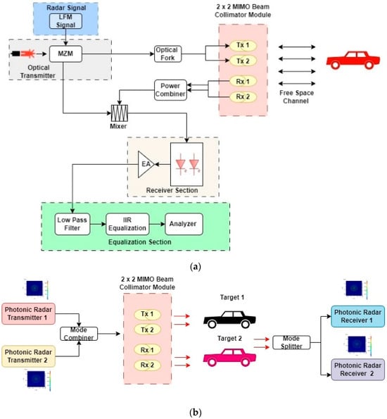
Figure 1.
Schematic diagram of proposed MDM-based MIMO photonic radar. (a) Photonic radar transmitter and receiver. (b) Concept of MDM in MIMO photonic radar for multiple target detection. MZM: Mach–Zehnder modulator; EA: electronic amplifier; LFM: low-frequency modulator; Tx: transmitter; and Rx: receiver.
In this setup, two distinct transmitters are used, each of which transmits on a specific Laguerre–Gaussian (LG) transverse mode. Transmitter 1 operates on the LG 20 mode, while Transmitter 2 operates on the LG 30 mode. These modes refer to different spatial light patterns characterized by their specific angular momentum and radial node properties, which are key in applications like mode division multiplexing.
Figure 2 presents the intensity distribution for the LG 20 and LG 30 optical modes. The LG 20 mode image displays a central bright spot surrounded by two concentric rings of light, which corresponds to its mode structure with two radial nodes. The LG 30 mode shows a similar central peak but with three surrounding concentric rings, denoting its three radial nodes.
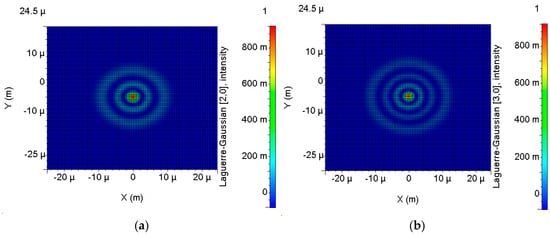
Figure 2.
Radial intensity distribution profiles: (a) LG 20 and (b) LG 30.
LG 20 and LG 30 modes are specific types of Laguerre–Gaussian (LG) modes, which are a family of laser beam modes characterized by their azimuthal and radial properties. In other words, they have 20 and 30 nodes in the radial and azimuthal directions, respectively. The LFM signal is modulated by the dual-port Mach–Zehnder modulator (DMZM), using the transverse optical signal as the carrier signal. The mathematical representation of the DMZM output is denoted as E(t) in Equation (1) [,]:
The term “IL” denotes the insertion loss, whereas VπRF and VπDC refer to the switching modulation voltage and switching bias voltage, respectively. For signal transmission towards the target in open space, the output from each transmitter is merged through a power combiner. Following this combination, the signals are intensified using an optical amplifier, which boasts a gain of 20 dB and a noise figure of 4 dB, before being projected through a lens. It is important to note that the Gamma–Gamma fading channel was considered for this work and is expressed mathematically as Equation (2) [,]:
The parameters involved in the equation include the operating range denoted by R, the beam divergence represented by θ, and the transmitter and receiver aperture diameters denoted by dT and dR, respectively. The impact of atmospheric conditions is also taken into account, denoted by α. In the case of autonomous vehicles (AVs), fog and rain are important factors that can limit the detection and ranging capabilities.
The attenuation values used in this study adhere to the International Visibility codes []. For instance, clear weather is assigned 0.14 dB/km, while light rain is assigned 2.5 dB/km, with 12.5 dB/km for strong rain, 25 dB/km for low fog, 50 dB/km for medium fog, and 75 dB/km for dense fog.
The implementation of Multiple-Input Multiple-Output (MIMO) technology in the receiver section of photonic radar systems can enhance their overall performance. A 2 × 2 MIMO scheme can be employed, which utilizes two transmitter antennas and two receiver antennas. This configuration offers improved resolution and accuracy, enabling the radar system to measure the location and velocity of targets with greater precision. By simultaneously transmitting two signals using two transmitter antennas, the system can obtain more detailed information about the target. In addition, the use of two receiver antennas allows the system to receive signals from various directions, minimizing the effects of interference and improving the sensitivity of the radar system. Furthermore, the incorporation of 2 × 2 MIMO can enhance the radar system’s ability to detect and track multiple targets simultaneously, even when they are in close proximity or moving in different directions. The system can differentiate signals from different targets and track them individually by leveraging multiple antennas to process the signals.
Within the transmitter, the modulated output signal is split into two segments. The first segment is transmitted through the channel for detection, while the second segment is utilized as the local oscillator signal in the receiver section.
The power of the received echo signal, denoted as Pr, can be calculated using Equation (3) [,]:
where the surface reflectivity of the target is ρt, the size of the irradiated zone at the target is Aill, the range of the target from the FMCW photonic radar is R, the diameter of the receiver aperture is D, the area of the target is At, the atmospheric loss factor is τatm, and the optical domain loss in transmission is τopt. When a signal is reflected off a moving target at a range distance R and velocity v, it experiences a Doppler shift given by fd = 2v/λ, where λ is the wavelength of the signal. The reflected signal undergoes a delay, denoted by τ, which is equal to twice the distance R to the target divided by the speed of light c. This delay is represented by the equation τ = 2R/c. This echoed signal, with both Doppler shift and delay, is collected by the telescope. The strength of the reflected signal Eref(t) can be expressed using Equation (4) []:
To mix the local oscillator signal Elo(t) with the echo signal power Eref(t), a balanced photodetector is employed, along with an ideal 3 dB optical coupler. The optical coupler functions by multiplying the input electrical signals, allowing for the frequency conversion and coherent detection of the received signals. By performing this multiplication process, the optical coupler facilitates the mixing of the signal and reference waveforms, leading to the generation of intermediate frequencies. These intermediate frequencies carry valuable information about the detected targets, enabling accurate target analysis and tracking. The reflected signal is detected by means of a photodiode that has a responsivity, represented by the symbol ℜ.
In the homodyne configuration, the signal-to-noise ratio is presented as Equation (5) []:
where the receiver bandwidth is Brx, the electrical charge is q (approximately equal to 1.6 × 10⁻¹⁹ c), the Boltzmann constant is kb (approximately equal to 1.38 × 10⁻²³ J/K), the receiver noise temperature is Tr, and the load resistance is RL.
As previously discussed, it is common practice to use an IIR filter after the photodiode in a photonic radar system to compensate for any potential atmospheric uncertainties that may affect the received signal.
The IIR filter is a type of digital filter that involves recursion. In the z domain, the transfer function can be represented as Equation (6) []:
4. Results
This section details the outcomes derived from simulating the proposed photonic radar system. This system is founded on FMCW technology and incorporates MIMO-IIR for the detection and ranging of various targets, utilizing the MDM scheme. For the purposes of this study, two independent targets were positioned at distances of 75 m and 55 m from the photonic radar.
The system’s configuration was designed with a bandwidth of 4 GHz, which is substantial for high-resolution target detection. The initial evaluation of the proposed system was conducted under optimal atmospheric conditions, where the weather was clear, and the targets were stationary. This setting provided a controlled environment to assess the system’s basic detection capabilities. The assumed atmospheric attenuation was relatively low at 0.2 dB/km, minimizing the impact on the signal’s strength over a large distance, which is essential for accurate target detection. The range frequency at which the echo signal occurs can be calculated using the fundamental principles of FMCW radar systems. The equation for typically takes into account the rate of change of frequency with respect to time given that the frequency of the transmitted signal increases linearly with time during the sweep. The formula to calculate the range frequency is given by []:
where B is the bandwidth, R is the range or the distance of the target, is the sweep time, and c is the speed of light. Figure 3 presents the results of this detection scenario, illustrating the system’s ability to identify multiple targets in such clear conditions. As illustrated in Figure 3, the proposed photonic radar system successfully detects two targets in clear weather conditions. The range frequency calculated using Equation (7) is 200 MHz for target 1 and 146.30 MHz for target 2, which matches the detected range frequency, as shown in Figure 3. This confirms the accuracy of the proposed system. Figure 3a displays the detection results without the utilization of the IIR technique, indicating maximum received power levels of −13 dBm for target 1 and −9 dBm for target 2. In contrast, Figure 3b exhibits the detection outcomes with the implementation of the IIR technique, showing significant power improvements with maximum received power levels of 13 dBm for target 1 and 14 dBm for target 2. The power improvement achieved using the IIR filter is calculated mathematically using Equation (7) as follows:
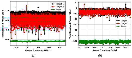
Figure 3.
Comparison of multiple target detection under clear weather conditions (a) without IIR and (b) with IIR.
According to the equation above, the percentage of power improvement is 200% for target 1 and 276.73% for target 2. These results demonstrate the significant impact of the IIR technique in increasing the detection capability of the proposed photonic radar system.
The performance of the proposed photonic radar is further tested for the impact of varying weather conditions. Figure 4 depicts the impact of different attenuation levels on the proposed photonic radar system. As illustrated in Figure 4, the proposed photonic radar system successfully detects two targets in attenuated weather conditions. Once more, the mathematically calculated range frequency matches the detected range frequency under heavy attenuation, as shown in Figure 4.
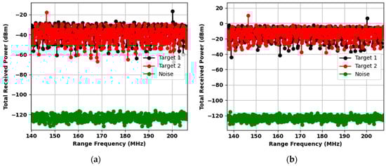
Figure 4.
Comparison of multiple target detection under severe weather conditions (a) without IIR target 1 and (b) with IIR target 1.
This confirms the accuracy of the detection of the proposed system even under heavy attenuation of 75 dB. Figure 4a displays the detection results without the utilization of the IIR technique for targets, and Figure 4b shows the detection of targets with IIR. The power improvement achieved using the IIR filter is visible in Figure 4b. It can be inferred that the utilization of the IIR technique in a photonic radar system can result in a reduction in the input power requirements. This, in turn, will lead to a decrease in power consumption, ultimately prolonging the lifespan of the autonomous vehicle’s battery. The proposed system incorporates a coherent detection scheme for the analysis of both the intensity and phase of a moving target. To evaluate the system’s performance, simulations were conducted with targets moving at varying speeds. The initial target was situated at a distance of 75 m and was moving at a velocity of 50 km per hour. Meanwhile, the second target was placed 55 m away, traveling at a speed of 20 km per hour. The corresponding Doppler frequencies for these targets were computed as 17.91 MHz and 7 MHz, respectively. It is worth noting that the Doppler shift is influenced by the direction of the target. There will be a decrease in range frequency when the target approaches the photonic radar (fr − fd). As the target distances itself from the photonic radar, the range frequency experiences an increment equal to the Doppler frequency, which can be represented as (fr + fd).
Figure 5 demonstrates the detection of moving targets at different speeds and distances from the photonic radar. The simulation encompasses two distinct scenarios: one where targets are advancing towards the radar, denoted as (fr − fd), and another where targets are receding from the radar, indicated as (fr + fd). The numerical simulation results in Figure 5a,b show that the peak range frequencies obtained align with the mathematically calculated values for both scenarios. The graph in Figure 5a displays two peaks for each target observed by the photonic radar. The peak for target 1 when the vehicle is moving away from the radar (fr + fd) is located at 217.61 MHz, whereas the peak for the vehicle moving towards the radar (fr − fd) is located at 182.09 MHz. These peaks are highlighted in black and red. Similarly, for target 2, the peak for the vehicle moving away from the radar (fr + fd) is at 153.30 MHz, while the peak for the vehicle moving towards the radar (fr − fd) is at 139.30 MHz. These peaks are highlighted in blue and yellow. Figure 5b illustrates how the detection of moving targets is affected by the IIR filter in terms of max. received power.
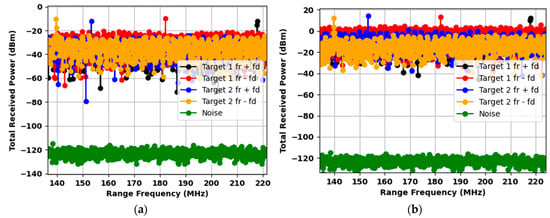
Figure 5.
Comparison of multiple moving targets (a) without IIR and (b) with IIR for target 1 and target 2.
Finally, the photonic radar system undergoes an evaluation for its proficiency in differentiating between targets that are in close proximity to each other, a characteristic known as range resolution. This aspect is crucial for the effectiveness and accuracy of the radar in complex environments. The range resolution (LRES) is dependent upon the bandwidth of the system as shown in Equation (9) []:
Given that a bandwidth of 4 GHz was utilized in this work, the calculated mathematical range resolution, as determined by Equation (9), is 3.75 cm. To conduct numerical simulations, target 1 was placed at a distance of 75 m, while target 2 was positioned 3.75 cm closer to target 1, at a distance of 74.9625 m, based on the mathematically calculated resolution. Due to the overlapping of the peaks, fractional shifting was performed for target 2, and after several iterations at varying distances, distinct peaks were obtained with a separation margin of 7 cm from target 1 at a distance of 74.930 m. The effectiveness of differentiating between both targets is demonstrated in Figure 6, where clear peaks are observed. Figure 6a illustrates the range resolution without the Infinite Impulse Response (IIR) filter, showing that while the peaks are distinct, part of the target 1 signal overlaps with the noise floor. This could potentially affect the accuracy and robustness of target detection. In contrast, Figure 6b demonstrates the significant improvement achieved with the addition of the IIR filter. The filter effectively suppresses noise and enhances the system’s ability to resolve targets with greater clarity and higher range resolution at larger distances. This improvement is essential for reliable target detection and discrimination, particularly in challenging environments with varying noise levels.
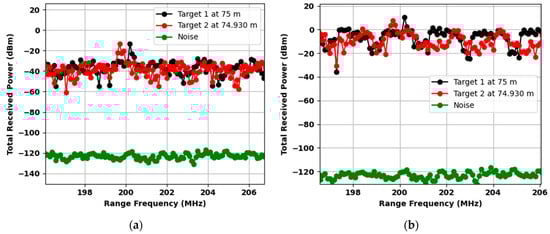
Figure 6.
Range resolution (a) without IIR and (b) with IIR for target 1 and target 2.
5. Conclusions
This work is focused on the development of a photonic radar system, utilizing mode division multiplexing, for applications in intelligent transportation systems. A homodyne configuration was employed for the detection of two individual targets, while the use of a 2 × 2 MIMO technique and IIR filter enhanced the system’s ability to operate effectively under turbulent weather conditions. The proposed system underwent evaluation via numerical simulations, showcasing effective detection of both targets. Target 1 was detected at a range frequency of 200 MHz, while Target 2 was identified at 146.30 MHz. These detections were achieved utilizing a bandwidth of 4 GHz. The impact of the IIR filter was also analyzed, resulting in power improvements of 200% for target 1 and 276% for target 2. The system’s detection capabilities were successfully validated through testing under high attenuation conditions of 75 dB/km. Additionally, the system was assessed for its ability to determine target speed, direction, and range resolution. This evaluation resulted in a range resolution of 7 cm, utilizing a bandwidth of 4 GHz. The outcomes from these numerical simulations were in consonance with the results calculated mathematically, offering additional validation for the efficacy of the proposed system.
6. Future Research Directions
While the current study demonstrates significant advancements in the integration of photonic radar technology with MIMO and IIR filtering for sustainable transportation, several future research directions can be pursued to further enhance this field:
- I.
- Enhanced Atmospheric Compensation: Future research could explore advanced atmospheric compensation techniques to further mitigate the effects of adverse weather conditions. This could involve the development of adaptive filtering algorithms and machine learning approaches to dynamically adjust to varying atmospheric disturbances.
- II.
- Integration with Other Sensing Technologies: Combining photonic radar with other sensing technologies, such as LiDAR, ultrasonic sensors, and thermal imaging, could provide a more comprehensive and robust detection system. Research could focus on the fusion of data from multiple sensors to improve the overall accuracy and reliability of autonomous vehicle systems.
- III.
- Extended Range and Resolution: Research efforts could aim at extending the range and improving the resolution of photonic radar systems. This could involve the use of higher frequency bands, advanced modulation techniques, and innovative signal processing methods.
- IV.
- Real-World Testing and Implementation: Conducting extensive real-world testing and pilot implementations of the proposed radar system in various urban and rural environments will be essential to validate its performance and identify practical challenges. Collaborative efforts with industry partners and transportation authorities could facilitate this process.
- V.
- Policy and Regulatory Frameworks: Research could also focus on the development of policy and regulatory frameworks to support the integration of advanced photonic radar systems in autonomous vehicles. This includes addressing safety standards, data privacy concerns, and the ethical implications of autonomous transportation technologies.
Author Contributions
Conceptualization, S.C. and A.S.; Formal analysis, S.C. and A.S.; Investigation, J.M.; Methodology, S.C. and A.S.; Software, A.S.; Supervision, J.M.; Visualization, Q.L. and Y.M.; Writing—original draft, A.S.; and Writing—review and editing, S.C. All authors have read and agreed to the published version of the manuscript.
Funding
This research received no external funding.
Institutional Review Board Statement
Not applicable.
Informed Consent Statement
Not applicable.
Data Availability Statement
No new data were generated in this manuscript.
Conflicts of Interest
The authors declare no conflicts of interest.
References
- Raja, K.; Kaliyaperumal, K.; Velmurugan, L.; Thanappan, S. Forecasting road traffic accident using deep artificial neural network approach in case of Oromia Special Zone. Soft Comput. 2023, 27, 16179–16199. [Google Scholar] [CrossRef]
- Testolina, P.; Barbato, F.; Michieli, U.; Giordani, M.; Zanuttigh, P.; Zorzi, M. SELMA: SEmantic large-scale multimodal acquisitions in variable weather, daytime and viewpoints. IEEE Trans. Intell. Transp. Syst. 2023, 24, 7012–7024. [Google Scholar] [CrossRef]
- Degrande, T.; Vannieuwenborg, F.; Verbrugge, S.; Colle, D. Deployment of Cooperative Intelligent Transport System infrastructure along highways: A bottom-up societal benefit analysis for Flanders. Transp. Policy 2023, 134, 94–105. [Google Scholar] [CrossRef]
- Kukkala, V.K.; Tunnell, J.; Pasricha, S.; Bradley, T. Advanced driver-assistance systems: A path toward autonomous vehicles. IEEE Consum. Electron. Mag. 2018, 7, 18–25. [Google Scholar] [CrossRef]
- Bishop, R. Intelligent vehicle applications worldwide. IEEE Intell. Syst. Their Appl. 2000, 15, 78–81. [Google Scholar] [CrossRef]
- Hu, L.; Ou, J.; Huang, J.; Chen, Y.; Cao, D. A review of research on traffic conflicts based on intelligent vehicles. IEEE Access 2020, 8, 24471–24483. [Google Scholar] [CrossRef]
- Zheng, X. Laser radar-based intelligent vehicle target recognition and detection system using image detection technology. J. Electron. Imaging 2023, 32, 011203. [Google Scholar] [CrossRef]
- Bae, Y.; Shin, J.; Lee, S.-G.; Kim, H. Field experiment of photonic radar for low-RCS target detection and high-resolution image acquisition. IEEE Access 2021, 9, 63559–63566. [Google Scholar] [CrossRef]
- Aldawoodi, A.; Bilge, H.Ş. Advancing Sustainable Marine Exploration: Highly Efficient Photonic Radar for Underwater Navigation Systems under the Impact of Different Salinity Levels. Sustainability 2024, 16, 2851. [Google Scholar] [CrossRef]
- Chaudhary, S.; Sharma, A.; Naeem, M.A.; Meng, Y. Target Detection in Challenging Environments: Photonic Radar with a Hybrid Multiplexing Scheme for 5G Autonomous Vehicles. Sustainability 2024, 16, 991. [Google Scholar] [CrossRef]
- Ding, Y.; Guo, S.; Zhou, W.; Dong, W. Microwave photonic radar for distance and velocity measurement based on optical mixing and compressive sensing. Appl. Opt. 2021, 60, 8534–8539. [Google Scholar] [CrossRef] [PubMed]
- Liang, D.; Shi, T.; Chen, Y. Photonic Generation of Multi-Band Linearly Frequency-Modulated Signal Based on a Dual-Parallel MZM. IEEE Photonics Technol. Lett. 2021, 33, 275–278. [Google Scholar] [CrossRef]
- Yang, Y.; Ma, C.; Fan, B.; Wang, X.; Zhang, F.; Xiang, Y.; Pan, S. Photonics-Based Simultaneous Angle of Arrival and Frequency Measurement System With Multiple-Target Detection Capability. J. Light. Technol. 2021, 39, 7656–7663. [Google Scholar] [CrossRef]
- Mohsan, S.A.H.; Khan, M.A.; Amjad, H. Hybrid FSO/RF networks: A review of practical constraints, applications and challenges. Opt. Switch. Netw. 2023, 47, 100697. [Google Scholar] [CrossRef]
- De, S.; Raj, A.B. A survey on photonics technologies for radar applications. J. Opt. 2023, 52, 90–119. [Google Scholar] [CrossRef]
- Sharif-Bakhtiar, A.; Carusone, A.C. A 20 Gb/s CMOS optical receiver with limited-bandwidth front end and local feedback IIR-DFE. IEEE J. Solid-State Circuits 2016, 51, 2679–2689. [Google Scholar] [CrossRef]
- Westhauser, M.; Finkenbusch, M.; Remmersmann, C.; Pachnicke, S.; Krummrich, P.M. Optical filter-based mitigation of group delay ripple-and PMD-related penalties for high-capacity metro networks. J. Light. Technol. 2011, 29, 2350–2357. [Google Scholar] [CrossRef]
- Hasanuzzaman, G.K.M.; Shams, H.; Renaud, C.C.; Mitchell, J.; Seeds, A.J.; Iezekiel, S. Cascaded Microwave Photonic Filters for Side Mode Suppression in a Tunable Optoelectronic Oscillator applied to THz Signal Generation & Transmission. IEEE Photonics J. 2021, 13, 5500111. [Google Scholar] [CrossRef]
- Maraikkayar, M.J.S.M.A.; Tamilselvi, R.; Beham, M.G.P.; Hasan, M.M.A. Novel Digital Filter Design for Noise Removal in Fetal Ecg Signals. Open Biomed. Eng. J. 2023, 17, e187412072212262. [Google Scholar] [CrossRef]
- Su, Y.; He, Y.; Chen, H.; Li, X.; Li, G. Perspective on mode-division multiplexing. Appl. Phys. Lett. 2021, 118, 200502. [Google Scholar] [CrossRef]
- Agrawal, G.P. Fiber-Optic Communication Systems; John Wiley & Sons: Hoboken, NJ, USA, 2012; Volume 222. [Google Scholar]
- Elghandour, A.H.; Ren, C.D. Modeling and comparative study of various detection techniques for FMCW LIDAR using optisystem. In Proceedings of the International Symposium on Photoelectronic Detection and Imaging 2013: Laser Sensing and Imaging and Applications, Beijing, China, 25–27 June 2013; SPIE: Redondo Beach, CA, USA, 2013; p. 890529. [Google Scholar]
- Elghandour, A.; Dianren, C. Study on detection techniques of distance and velocity by chirped LIDAR. In Proceedings of the 2012 International Conference on Optoelectronics and Microelectronics, Changchun, China, 23–25 August 2012; pp. 354–358. [Google Scholar]
- Awan, M.S.; Csurgai-Horváth, L.; Muhammad, S.S.; Leitgeb, E.; Nadeem, F.; Khan, M.S. Characterization of fog and snow attenuations for free-space optical propagation. JCM 2009, 4, 533–545. [Google Scholar] [CrossRef]
- Goldfarb, G.; Li, G. Chromatic dispersion compensation using digital IIR filtering with coherent detection. IEEE Photonics Technol. Lett. 2007, 19, 969–971. [Google Scholar] [CrossRef]
- Pan, S.; Zhang, Y. Microwave photonic radars. J. Light. Technol. 2020, 38, 5450–5484. [Google Scholar] [CrossRef]
Disclaimer/Publisher’s Note: The statements, opinions and data contained in all publications are solely those of the individual author(s) and contributor(s) and not of MDPI and/or the editor(s). MDPI and/or the editor(s) disclaim responsibility for any injury to people or property resulting from any ideas, methods, instructions or products referred to in the content. |
© 2024 by the authors. Licensee MDPI, Basel, Switzerland. This article is an open access article distributed under the terms and conditions of the Creative Commons Attribution (CC BY) license (https://creativecommons.org/licenses/by/4.0/).