1. Introduction
In the field of civil engineering, concrete materials are widely used, but due to their low tensile strength, it is easy to cause cracking of components. The appearance of cracks will not only cause the corrosion of steel bars and concrete carbonization and other problems such as affecting the safety of the structure and reducing the service life of the structure, but also cause water seepage and other problems that affect the normal use of the structure. Traditional seepage control and sealing techniques such as concrete seepage control walls and split curtain grouting have small construction depths and poor stratigraphic adaptability; some require large or heavy equipment, which is expensive, and it is difficult to access the leakage location. Cement-based grouting materials exhibit volume shrinkage during the hardening process. Their material viscosity often cannot accurately find the source of leakage, and the sealing effect is not good. Many existing chemical grouting materials, such as epoxy resins, acrylates, phenolic resins, polyurethane, etc., play an important role in the repair of concrete defects. However, organic materials are poorly compatible with cement-based materials and are prone to aging; the materials are highly viscous, have limited penetration depth in cracks and can only seal wider cracks of a modest depth [
1,
2]. In addition, the chemical composition of these materials is mostly toxic, and after the poisoning incident caused by the use of acrylamide-type grouting materials for reinforcement and plugging in Fukuoka, Japan, countries began to strictly prohibit the production of toxic chemical grouting materials, and the development of chemical grouting materials has been seriously affected since then.
Microbial mineralization sealing of concrete crack technology is discussed in this case. The material used in this technology has a low viscosity before curing and, with the help of negative pressure, can penetrate into the crack, use microbial deposition minerals to achieve the effect of plugging and automatically find the location of leakage for effective seepage prevention. Thus, this technology achieves the effect of exploration and plugging. It is particularly important in some complex environments. Calcite produced by microorganisms is stable and combined with concrete materials. Repaired concrete materials with acid resistance, alkali resistance, freezing and thaw cycle resistance, carbonization resistance and permeability resistance have been improved and not fail due to the aging of the materials [
3]. Remediation technology using microorganisms to induce mineral deposition is an internationally advanced technology with a range of knowledge involving civil, chemical and biological disciplines, and is a new research direction at the intersection of several disciplines. Microbial remediation technology utilizes the metabolic activity of microorganisms, which are part of nature, green and non-polluting. Therefore, the use of microbial-induced mineral deposition technology has unparalleled superiority over current restoration methods.
Microorganisms were induced to generate CaCO
3. The process of MICP is composed of a complex series of biochemical reactions. Some alkalophilic soil microorganisms are able to use their own production of urease enzymes to break down urea into NH
3 and CO
2, and as the amount of ammonia produced by decomposition increases it causes a rise in pH in the surrounding environment, causing CO
2 to exist in solution as CO
32−. At this point, if the bacteria are surrounded by Ca
2+, the negatively charged organic monolayer in bacterial cells constantly chelates Ca
2+ to give rise to CaCO
3 crystal deposition [
4]. In 1973, Boquet et al. found that some microorganisms in nature could use their own life activities to induce CaCO
3 deposits [
5]. Since then, some foreign scientific research institutions have been continuously investing in the research of the deposition mechanism and engineering applications. This technology is not only applied to repair the cement base surface defects, improve the compressive strength, seepage resistance, acid resistance, alkali and freeze and thaw cycle capacity of concrete, but also can be used for sand fixation and foundation reinforcement. The study of microbial plugging was mainly initiated by the Dutch research institute GeoDelft, which aims to adjust soil characteristics and change soil coefficients through the development of technology [
6]. Blauw closed the small holes in the middle partition of the tube until they were blocked by filling the nutrients into the PVC tube filled with sand [
7]. Cyprien et al. injected bus spore eight-stack fungus into the sand column and continued injecting calcium chloride and urea into the sand column, and, three weeks later, the penetration rate of the saline in the sand column was significantly reduced [
8]. Li class Bacillus basstrii, urea and CaCl2 were used as solutions to block the cracks in the artificial cores, and the test shows that it is very effective to fill the sand or quartz powder in the wide cracks and then plug the cracks with bacteria to repair them [
9]. Chunxiang Qian et al. used the bacterial film coating method to reduce the water absorption coefficient of concrete samples by one order of magnitude, and the impermeability was significantly enhanced [
10]. Qiang Jia et al., in the plugging project of the Weidong Xindu underground parking lot in Jinan Weidong, used the method of implementing biological grouting horizontally to successfully block cracks in the grouting groove outside of the wall [
11].
Tittelboom et al. designed a set of comparative tests, which showed a significant improvement in the impermeability and durability of the repaired members by direct observation, ultrasonic testing and thermogravimetric analysis [
12]. Ramakrishnan et al. mixed bacteria, nutrients and sand and then filled them inside the concrete cracks. The tests revealed that the strength of the specimens was significantly increased and there was more deposition of calcium carbonate in the surface area of the concrete specimen cracks, which was due to the high bacterial urease activity in the surface area where there was sufficient oxygen [
13,
14]. Ruixing Wang et al. compared the compressive strength of concrete members before and after microbial remediation through an experimental study. It was found that the compressive strength recovery values of the concrete members after microbial repair were significantly improved. In addition, the crack repair was completed by grouting and injection for different size cracks, and the ideal repair effect was achieved, which created a new idea for the implementation process of MICP technology [
15,
16]. Sun et al. conducted sealing experiments on concrete specimens with different crack widths at low temperatures using the MICP technique and evaluated the effectiveness of the repair using live cell concentration, acoustic time values, uncompressed compressive strength and calcium carbonate productivity as indicators. Finally, the cracks were successfully sealed at a low temperature using the MICP technique. The strengths of the specimens with different crack widths were restored. The smaller the crack width, the higher the microbial utilization rate [
17].
Chengcheng Zhao performed microbial grouting to seal the cracks in nine groups of concrete specimens with different crack widths and crack depths, and each specimen was tested for seepage resistance after the sealing was completed. The test results showed that all specimens could withstand a water pressure of at least 0.05 MPa; more than half of the specimens could withstand a water pressure of at least 0.1 MPa. This was able to meet the seepage resistance requirements of general underground buildings [
18]. Huan Jiang conducted plugging tests on transversely cracked concrete cracks of different lengths and widths using the microbial-induced calcium carbonate deposition technique. The results showed that the larger the seam depth within a certain range, the shorter the sealing time of concrete cracks. Bacterial activity is the main factor affecting microbial-induced calcium carbonate deposition [
19]. Xiaohan Chen designed nine groups of concrete specimens using the orthogonal test method and selected four influencing parameters such as different crack inner wall roughness, crack depth, different calcium source solutions and whether oxygen was passed or not for comparison tests. The results show that the rougher the crack and the deeper the crack, the easier it is to seal. The influence on the sealing effect of calcium source type and whether oxygen is passed or not is small. By observing the section of the specimen after cutting and sealing, it can be seen that calcium carbonate presents the characteristics of being denser in the middle and looser at both ends along the horizontal direction of the crack; along the vertical direction, it presents the characteristics of being denser in the middle and lower parts and looser at the upper part [
20].
Thus, the effect of using microorganisms for crack repair has been verified in engineering, but the generation and evolution mechanisms of the plugging layer still need to be studied.
Related studies on the deposition law of microbial grouting to repair concrete cracks have been carried out by our group, among which Peng Ding used top gravity grouting to seal vertical concrete cracks. The experiments investigated the deposition law of calcium carbonate inside the cracks under the influence of these factors: the ratio of bacterial liquid to the volume of cracks, the presence or absence of fixed liquid, and the presence or absence of a filter layer. More satisfactory experimental results were achieved [
21,
22]. However, the following problems remain to be solved in the experimental study.
The top gravity grouting method makes the bacterium solution stay in the crack for a short time, and the bacterium solution cannot react fully with the calcium source inside the crack before being lost in the bottom waste collection tank. Part of the calcium carbonate generated inside the crack will also be lost with the solution by the scouring effect of the bacterium solution and the calcium source solution. Due to these two reasons, the number of grouting cycles required to achieve sealing of cracks in concrete specimens is higher and the sealing period is longer, resulting in a large amount of waste of the bacterial solution and an increase in the time and cost required for grouting and sealing.
It is necessary to further reveal the law of calcium carbonate generation within concrete cracks and improve the grouting process. To improve the deficiencies in the previous experimental studies, the following research and innovations were made in this paper.
- (1)
In terms of grouting operation process, the method of sealing the bottom of the test block and grouting under pressure from the bottom is adopted, which can make the bacterial solution stay inside the cracks and react fully with the calcium source solution.
- (2)
In terms of variable parameter selection, the effect of different crack widths on calcium carbonate deposition patterns was studied, and the crack widths were taken as 1.0 mm, 1.5 mm and 2.0 mm, respectively. The effect of the presence or absence of medium in the crack on calcium carbonate deposition was studied, and the medium added was quartz sand. The effect of different grouting methods on crack sealing was studied, including pressure grouting with bottom sealing, gravity grouting with bottom sealing, and top unsealed grouting. The effect of different grouting methods on crack sealing was investigated, including bottom sealing pressure grouting, bottom sealing gravity grouting, and top non-sealing gravity grouting. The advantages and disadvantages of pressure grouting at the bottom and gravity grouting at the top are compared through comparative tests.
- (3)
After the grouting test, the crack repair effect was characterized by a water seepage test, calcium carbonate generation, and the distribution of calcium carbonate in the cracks to reveal the distribution of calcium carbonate deposition in the cracks under different influencing factors.
In this paper, the bottom of the vertical fracture is closed and pressure grouting is used to repair the microbial mineralization of the fracture. In order to study the amount of grouting fluid and the repair period, seven sets of parallel tests were designed under the control of three variable parameters: different crack width (1.0 mm, 1.5 mm, 2.0 mm), whether quartz sand medium was filled in the crack, and different grouting methods (bottom-up pressure grouting, top-down self-grouting). To clarify the sedimentary distribution rule of CaCO3 in the crack, which is microbial, it provides a theoretical basis for the application and popularization of concrete crack repair technology in seepage control and plugging of underground engineering.
The method of sealing and pressure grouting at the bottom of vertical cracks adopted in this test is not found in previous related studies and is one of the important innovations of this test. For the sealing of vertical cracks in concrete, the more widely used sealing methods are horizontal grouting on the outside of the crack and gravity grouting on the top of the crack. The research in this paper provides a new sealing method for microbial repair of concrete cracks in practical application, which makes the application of this technology more extensive and more mature.
3. Results and Discussion
3.1. Test Phenomenon
At the beginning of grouting, the solution in the crack was observed from the top of the test block crack without white material. After reaching a certain number of grouting cycles, the white suspended material began to form at the top of the crack. After standing for a period of time, the white suspended material was deposited inside the crack.
With the increase in the number of grout cycles, the amount of bacterial liquid, urea mixture and calcium source solution injected in each round of grouting gradually decreased, and the pressure required to fill the grout gradually increased. The amount of grout used in the group with quartz sand medium was much less than that used in the group without medium, and the pressure required for grouting was greater.
3.2. Number of Grouting Cycles
Influenced by different crack widths, whether there is medium in the crack and the direction of different grouting, the number of grouting cycles required for the sealing of each test block crack was different, as shown in
Table 3.
According to
Table 3, the larger the crack width, the more grouting cycles are needed to complete the crack closure. This is because the larger the crack width, the thicker the calcium carbonate that requires bacterial mineralization deposition. Due to the limited amount of bacteria injected each time, more times are needed to complete the plugging. The addition of quartz sand medium to the crack can greatly reduce the number of grouting cycles needed to complete the crack sealing. On the one hand, the filling of the quartz sand medium indirectly reduces the crack and makes the width of the crack smooth. On the other hand, the quartz sand medium is a porous structure, which provides a more favorable place for the deposition of calcium carbonate.
3.3. Water Seepage Test Results
A water seepage test is a simple and effective method to test the crack sealing effect. The fixed water head method was used to measure the water seepage amount of the concrete crack for 5 min at a height of 150 mm of the water head. The average seepage velocity of each specimen was obtained by dividing the seepage amount by the seepage time, as shown in
Table 4.
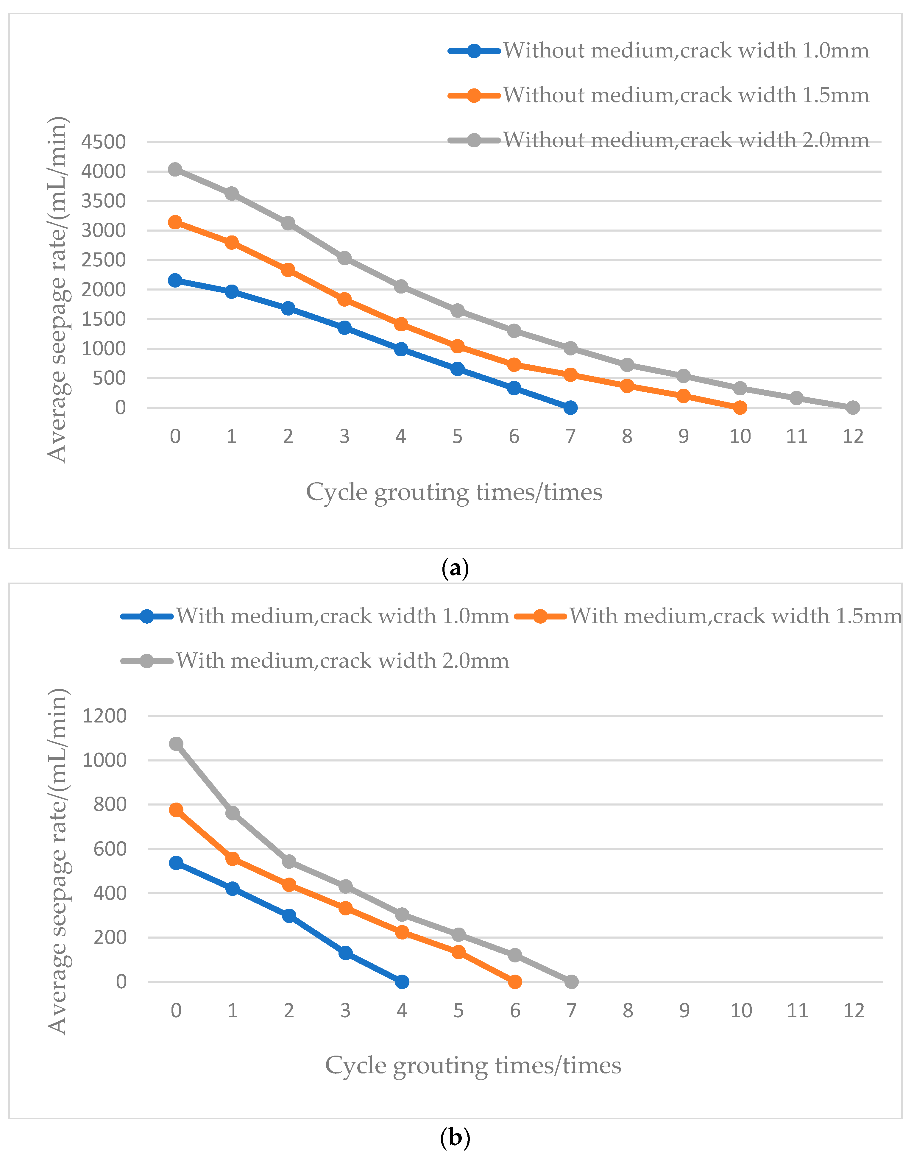
The curve draws the relationship between the average water seepage speed and the grouting cycle number of the different cracks in Groups 1–6 of each sub-block (bottom-up pressure grouting comparison group) and whether the cracks are filled in
Table 4, as shown in
Figure 6.
According to
Figure 6, with the increase in grouting cycles, the average seepage velocity in the crack gradually decreases. This is because the amount of calcium carbonate generated in the crack gradually increases with the number of grouting cycles, the crack space is constantly decreasing, and the water seepage per unit time will gradually decrease.
Under the condition that the crack is not filled with medium, the average seepage velocity in the crack decreases, and the grouting cycle frequency for a 1 mm crack width is reduced from 12 times to 7 times. Under the condition that the crack is filled with medium, the same conclusion is reached: the number of grouting cycles is reduced from 7 times to 4 times. This is because the smaller the crack width, the smaller the crack volume, the less water seepage per unit of time, and the less repetitions the grouting cycle needs.
3.4. Results of Calcium Carbonate Production Test
Calcium carbonate production is another intuitive and effective index to test the crack sealing effect, which can accurately reflect the influence of different factors on the crack repair effect. After the crack repair was completed and the crack’s inner wall was observed, a file was used to scrape the calcium carbonate generated by the inner wall of the crack surface, the scraped calcium carbonate powder was weighed on the filter paper, the weight of the known medium in the crack was reduced, and the amount of calcium carbonate generated in the crack was determined. This is shown in
Table 5.
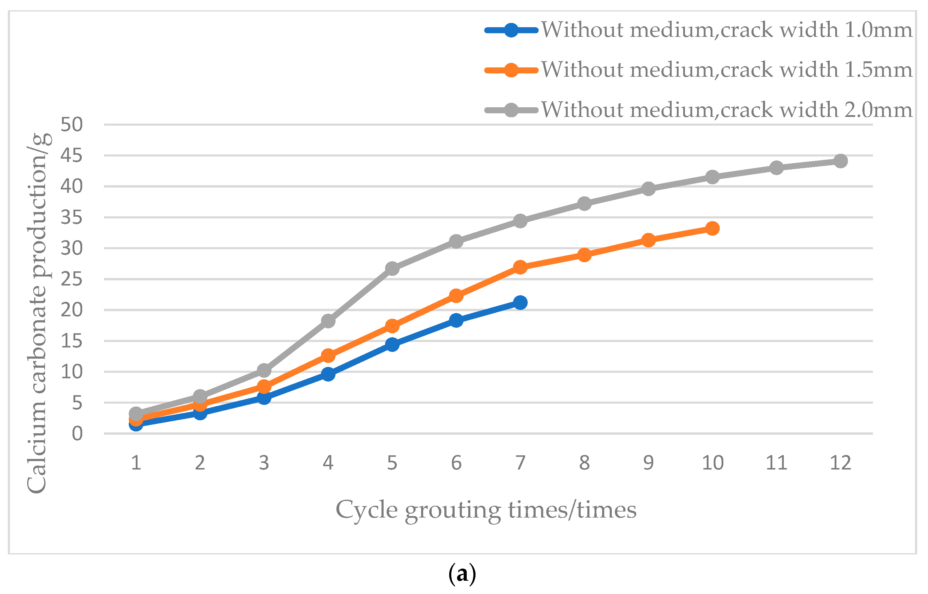
The curve draws the relationship between the amount of calcium carbonate production and the number of grouting cycles in Groups 1 to 6 (bottom-up pressure grouting comparison group) and the filling medium in
Table 5, as shown in
Figure 7.
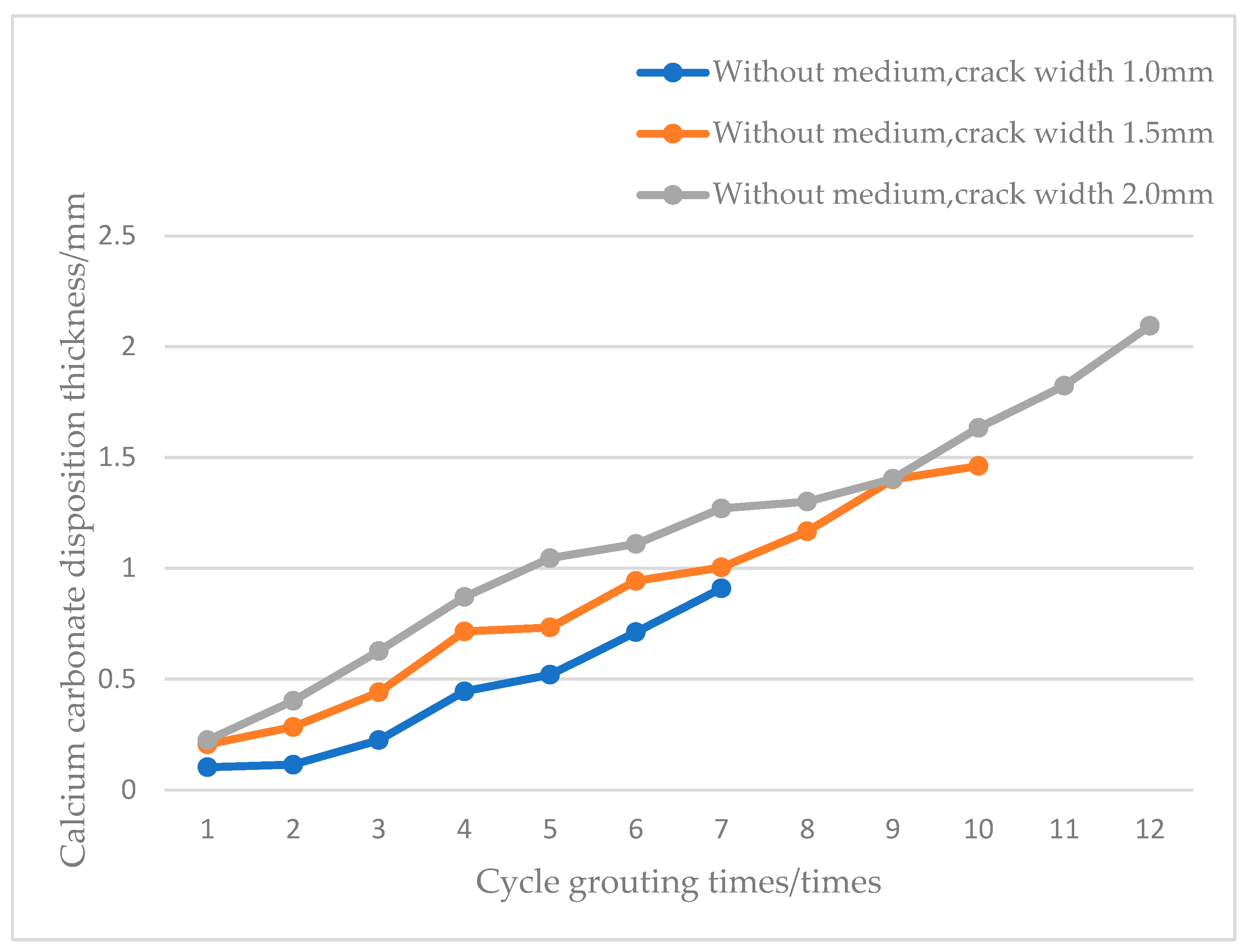
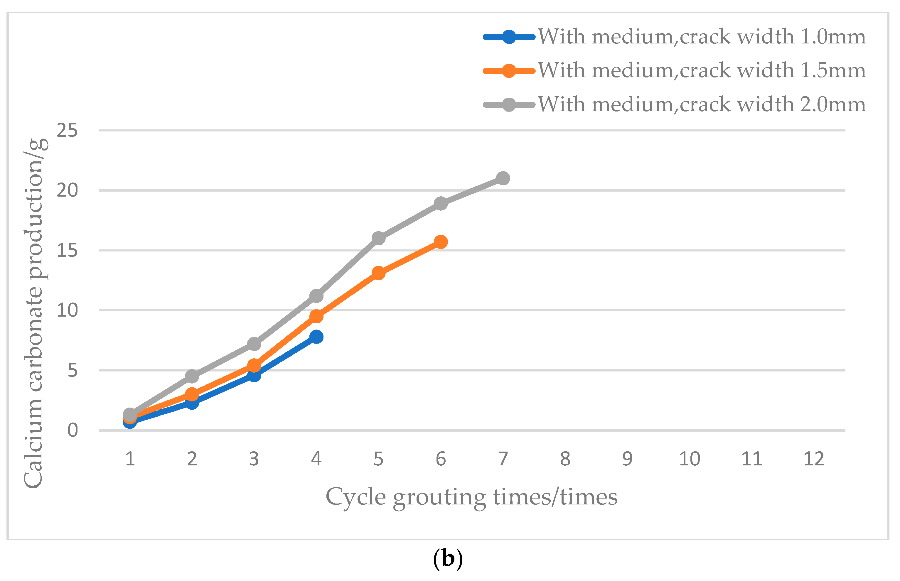
According to
Figure 7, the wider the crack width of the test block, the more single-grouting cycles and final calcium carbonate production amount. This is because the test block is sealed at the bottom. Each grouting amount is double the crack volume. Therefore, if the crack width is wider, the total amount of grouting fluid will be more, so the amount of calcium carbonate production increases with the increase in the crack width. Under the same crack width condition, the amount of calcium carbonate production is less than the group without medium. This is because the addition of media reduces the volume of the crack, and each round of grouting contains less bacterial liquid.
As the number of grouting cycles increases, the amount of calcium carbonate produced gradually increases, so the deposition of calcium carbonate generated in the crack gradually accumulates. However, it can be seen from
Figure 7 that the amount of calcium carbonate production is not a simple linear increase: the amount of calcium carbonate production is relatively slow at the beginning of grouting, then the amount of calcium carbonate increases rapidly, and the amount of calcium carbonate production tends to be slow when the test block cracks approach becoming blocked. This is because, at the beginning of grouting, the location of bacterial attachment in direct contact with the concrete inner wall affects the activity. Therefore, the amount of calcium carbonate produced is relatively small. Growth rate is also relatively slow; as the number of grouting cycles increases, the inner wall of the crack generates a certain thickness of calcium carbonate. Bacteria no longer directly contact the concrete inner wall. Bacterial activity can be maximized to the extent that the amount of calcium carbonate production increases rapidly. After reaching a certain number of grouting times, with the increasing amount of calcium carbonate produced in the crack, the crack is filled with calcium carbonate, the infused grout is gradually reduced and the growth rate of calcium carbonate production gradually slows down until the crack is completely blocked.
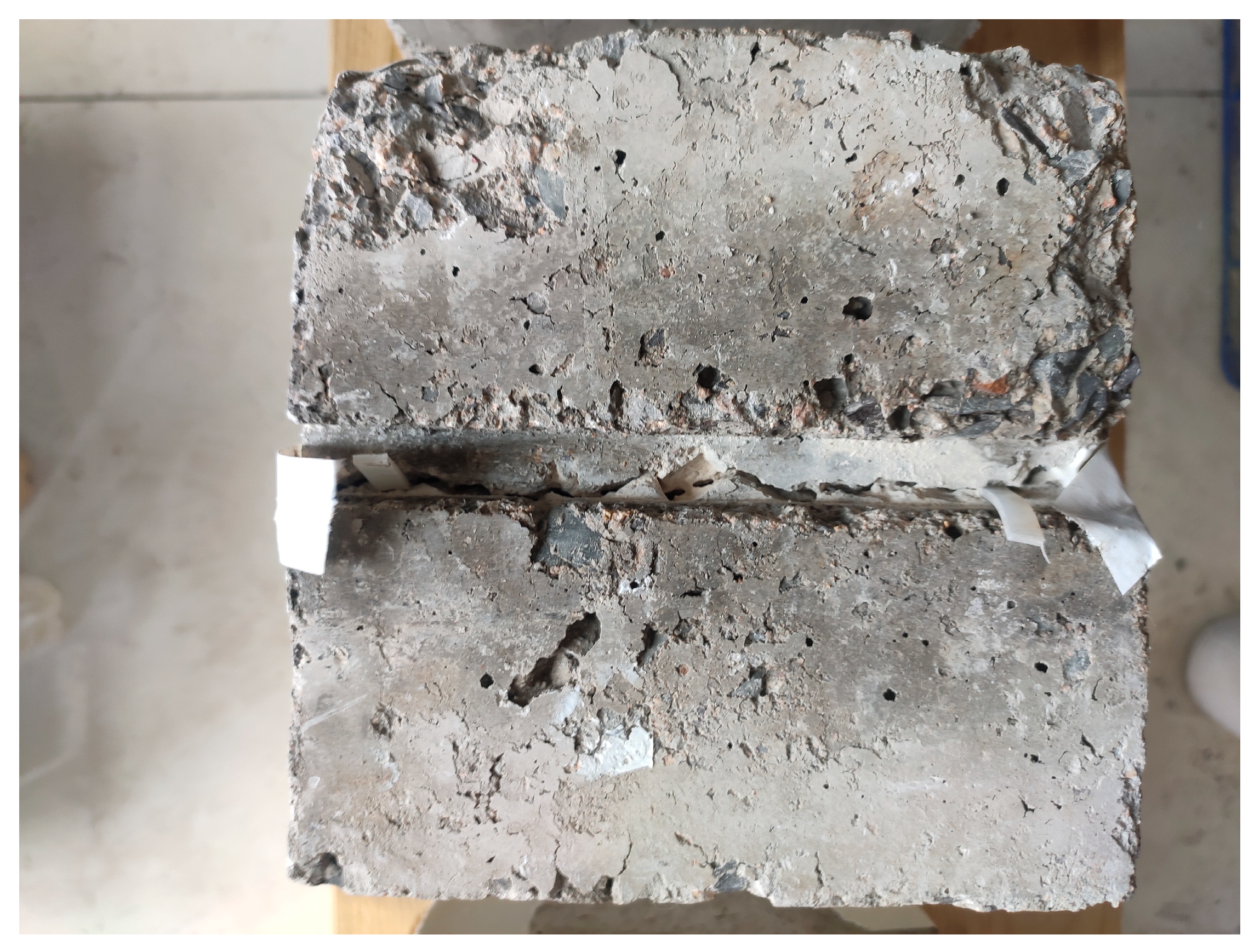
3.5. Observation Results of Calcium Carbonate Deposition Thickness within Cracks
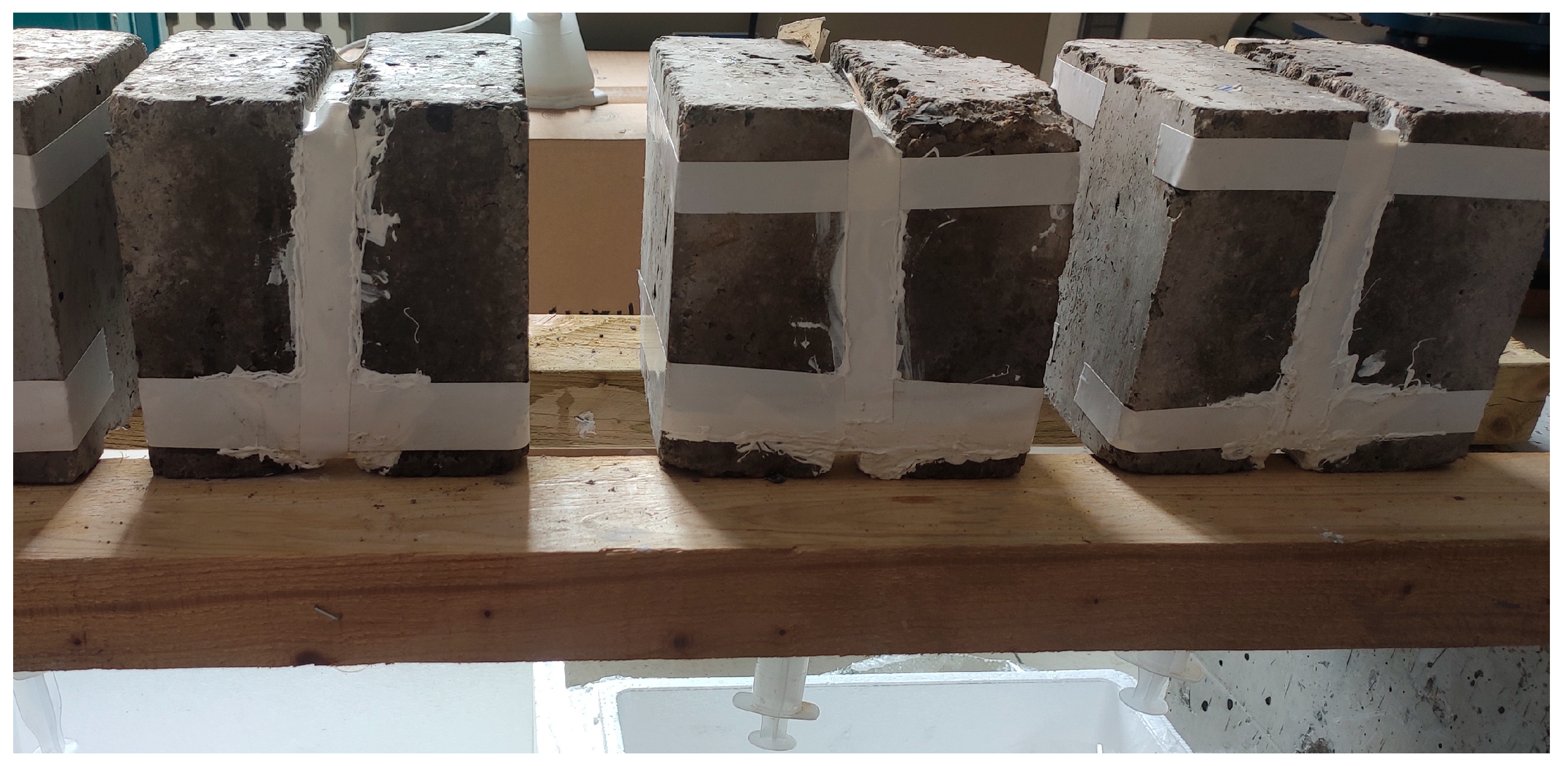
After the water seepage test, the test block was placed under natural conditions to dry, then all the waterproof tape around the test block was removed and the test block was cut vertically perpendicular to the crack with a cutting machine. The distribution law of microbially induced calcium carbonate inside the crack could be revealed by observation with an electron microscope under different influencing factors. Because the group of the filling media in the crack is the sealing layer formed together by the media and calcium carbonate, it is not easy to observe the formation thickness of calcium carbonate formation. Therefore, the generated thickness of calcium carbonate observed by electron microscope is only for Groups 1, 2 and 3, and the vertical profile of the crack sealing is shown in
Figure 8.
Starting from the bottom of the crack, take the four observation points of 0 mm, 50 mm, 100 mm and 140 mm, and record the thickness of calcium carbonate deposition at each observation point to obtain the deposition pattern of calcium carbonate along the crack height in the 1.0 mm, 1.5 mm and 2.0 mm specimens. See
Table 6,
Table 7 and
Table 8, respectively.
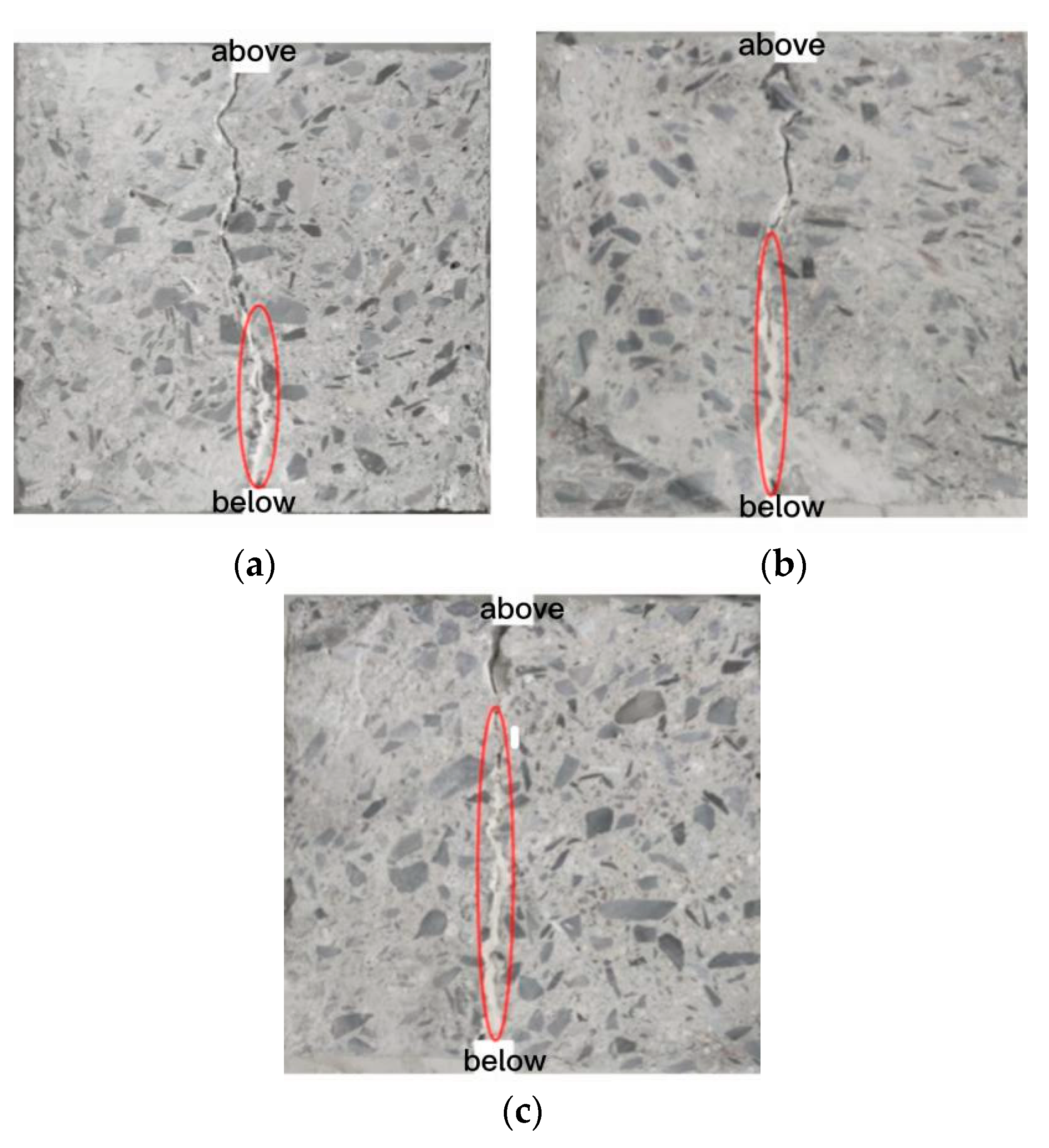
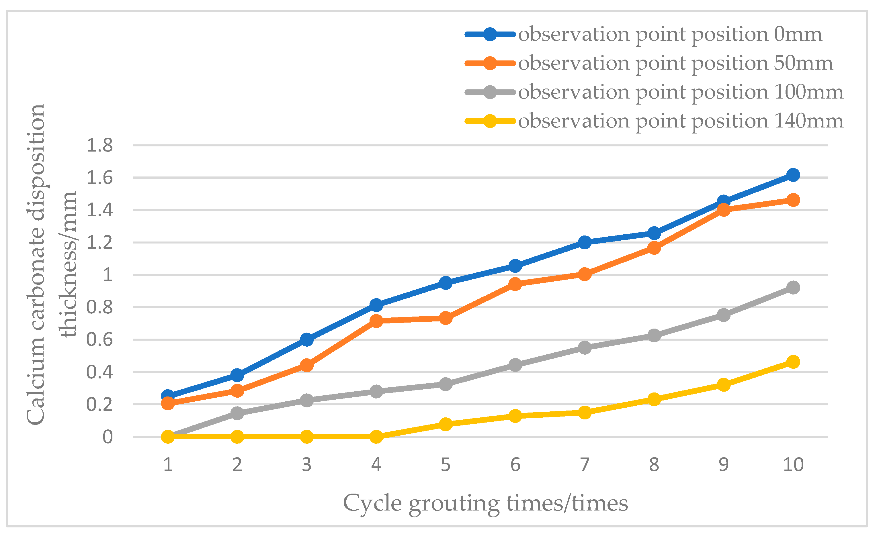
In order to clearly state the rule of calcium carbonate deposition, draw the relationship between the calcium carbonate deposition thickness and the number of grouting cycles at the observation point of 50 mm from the crack bottom, as shown in
Figure 9, and the relationship between the calcium carbonate deposition thickness of Group 2 (crack width 1.5 mm), as shown in
Figure 10.
According to
Table 6,
Table 7 and
Table 8 and
Figure 9 and
Figure 10, the thickness of the calcium carbonate deposition is gradually increased as the number of grouting cycles increases. At the same observation point location, the larger the width of the crack, the thicker the calcium carbonate deposition in the crack’s inner wall and the greater the amount of calcium carbonate generated.
With the same crack width conditions, calcium carbonate is first deposited at the bottom of the crack and then develops upwards. With the increase in calcium carbonate, the thickness of calcium carbonate gradually decreases. In the first few rounds of grouting, there is no calcium carbonate at the observation point at the top; the calcium carbonate starts to accumulate at the top of the top of the crack. In Group 2, the calcium carbonate thickness at the crack’s top is only 29% of the bottom of the crack.
3.6. Comparison of Bottom Pressure Grouting and Top Gravity Grouting Test Results
In the previous test study of seepage prevention in the research group, the gravity grouting at the top of the crack and the bottom is not closed. Although this grouting method is simple and convenient to operate, a large number of bacterial liquid cannot react in time to generate calcium carbonate stored in the cracks and is lost, resulting in the waste of grout liquid. In this test, Groups 1–6 used the bottom seal bottom-up pressure grouting to repair the test block. In order to reflect the superiority of the grouting method, a group of contrast groups (Group 7, with 1.0 mm crack width, bottom sealing and top gravity grouting) was specially designed to show the advantages of the bottom pressure grouting through comparison.
The number of grouting cycles, the total amount of grouting fluid and the total amount of bacterial fluid required for the three different grouting methods are shown in
Table 9.
As can be seen from
Table 9, the number of grouting cycles and the total amount of grouting and bacterial fluid required for sealing the bottom of the cracks were relatively small, and the total amount of grouting and bacterial fluid was 78% and 32% of the bottom unsealed control group, respectively. This is because the sealed crack bacterial solution treated at the bottom can fully react with the calcium source solution to avoid the early loss of bacteria in the crack. Moreover, due to the unsealed bottom crack and the calcium source solution, a part of the calcium carbonate is lost from the bottom of the crack, so more grouting cycles and bacterial solution are needed.
With the same bottom seal, the top gravity grouting has more cycles and total bacterial fluid than the bottom pressure grouting. This is because the top gravity grouting is not conducive to the exclusion of gas in the crack, which affects the compactness of calcium carbonate deposition.
It can be seen from the comparative test that, although the bottom sealing pressure grouting method is more complicated in the test block production and perfusion method, it can reduce the number of grouting cycles required by the crack sealing and greatly reduce the amount of grouting fluid and save the cost.


