1. Introduction
Water electrolysis (WE) stands at the forefront of hydrogen (H
2) production technology. By utilizing electrical energy to split water into hydrogen and oxygen, WE taps into the potential of renewable energy sources (RESs). “Green hydrogen” refers to hydrogen produced through a process that relies on renewable energy sources such as solar, wind, hydro, or geothermal energy, typically through electrolysis. The term “green hydrogen” is often used to distinguish it from “grey” or “brown” hydrogen. Grey hydrogen is produced using fossil fuels, primarily natural gas, with associated carbon dioxide emissions. Brown hydrogen is similarly produced using fossil fuels, often through coal gasification. In contrast to the dominant method of steam methane reforming [
1], which contributes to global emissions, WE for green hydrogen production harnesses RES-generated electricity. This shift not only decarbonizes hydrogen production but also serves as a vital energy storage solution. Hydrogen produced through green electricity serves as a valuable tool for stabilizing the energy system, facilitating the increased integration of intermittent renewable sources like wind, hydroelectric, and photovoltaic (PV) solar. This approach contributes to the broader adoption of these new renewables, addressing their inherent challenges of intermittent generation and supporting a more reliable and resilient energy infrastructure.
Electrolytic hydrogen acts as a linchpin, balancing surplus green energy, bolstering grid stability, and transforming sectors resistant to conventional electrification. Notably, it holds the key to decarbonizing challenging domains like long-haul transport and industries where emissions reduction poses a formidable challenge, like hard-to-abate sectors [
2]. These transformative potential underscores the pivotal role of water electrolysis in shaping a sustainable and low-carbon future. In the realm of energy, hydrogen is a widely debated subject. However, discussions often suffer from oversimplification, lacking a comprehensive perspective that illuminates its broader implications. There is a need to transcend surface-level analysis and embrace a holistic view, acknowledging the profound implications of hydrogen within the larger energy landscape. In the energy sector, confusion often arises between resources, energy carriers, and end uses. The recent hydrogen debate is no exception. Hydrogen is indeed a carrier, and while it can aid energy transition, it cannot solve all problems. Developing green hydrogen is crucial. It can boost renewable energy generation, even for unconventional uses. Advancements in electrolysis will undoubtedly enhance the production of green hydrogen [
3,
4]. The development of green hydrogen is paramount, as it has the potential to amplify renewable energy generation, including for unconventional applications. Advances in electrolysis are poised to significantly improve green hydrogen production. Although hydrogen can be derived from fossil fuels with some economic advantages, this route is inefficient energy-wise, dissipating a substantial amount of energy.
Water electrolysis relevance is evident today: the electrolytic process involves many variants and variables, such as the type of ion transport medium, electrodes and catalysts, the operating temperature, pressure, voltage and current density, and the electrolyzer size; thus, analysis of cell, stack, and system levels are necessary. Many scientific and technological problems are still open and, thus, are to be investigated, such as electrolyzers’ scaling up, performance measurement, and association between electrolytic H2 production and RESs. In today’s scientific and technical landscape, numerous projects focus on hydrogen and its related domains. Yet, amidst this vast realm, numerous themes and microtopics remain open and often elusive. Distinguishing between established knowledge and ongoing research objectives poses a challenge. This article endeavors to provide clarity, meticulously assessing the existing body of knowledge while highlighting debated topics. We aim to delineate the current state-of-the-art, discern what is consolidated, and shed light on the persistently open avenues of research. In particular, the objective of this paper is to provide an elucidating critical analysis of water electrolysis for green hydrogen production. This includes the description of the main electrolysis technologies and energy balance considerations about the various techniques. An incisive analysis of electrolytic cell physics and main technologies’ irreversibility is carried out to identify the aspects that would require more investigation to increase efficiency.
The existing literature extensively covers hydrogen production through various electrolysis technologies and the various elements involved [
5,
6,
7,
8,
9,
10,
11,
12,
13,
14,
15,
16,
17,
18,
19,
20]. The predominant focus has been on specific technological aspects. It is equally crucial to establish a methodological framework based on energy system analysis. This approach facilitates a comprehensive evaluation of green hydrogen integration within real energy systems, enabling more precise assessments of water electrolysis’ impact and economic feasibility.
The electricity consumption associated with electrolysis currently stands at around 55 kWh per kilogram of hydrogen produced. H2’s lower calorific value is approximately 33 kWh per kilogram of hydrogen. This disparity underscores the critical need for optimization strategies targeting various elements within the electrolysis system, including electrodes, electrolytes, catalysts, and membranes. Through meticulous research and development, advancements in these components can lead to substantial reductions in energy consumption, paving the way for more energy-efficient and sustainable hydrogen production methods. Our study aims to connect in-depth technological analyses with the broader context of the energy system. By examining the entire electrolytic process and adopting a holistic perspective, we strive to make a meaningful contribution to the existing understanding of green hydrogen production and its possible applications. While significant attention in the scientific literature is devoted to electrolysis and hydrogen production, practical applications often remain on the periphery. The challenge lies in bridging the diverse elements involved. Our contribution aims to elucidate the intricacies of this topic, highlighting its complexity.
This paper is organized as follows: In
Section 2, a brief overview of electrolysis, and its significance in sustainable energy production, is provided.
In
Section 3, the fundamentals of water electrolysis for hydrogen production are outlined. Electrochemical analysis of the electrolytic cell is conducted for a better understanding of the process.
Section 4 illustrates the main technologies for electrolysis and open fronts of research and development. In
Section 5, the commercially available technologies, the problem of scaling up the sizes of electrolyzers, and the association between electrolytic hydrogen production and energy sources are investigated. Considerations about green energy sources necessary for electrolytic hydrogen production are proposed.
The Conclusions section (
Section 6) provides a condensed overview of this paper’s analysis, emphasizing the possibilities and potential of integrating electrolysis and green hydrogen into actual energy systems. This segment encapsulates essential points and implications, delivering a thorough comprehension of the challenges and opportunities linked to hydrogen production through water electrolysis for energy transition.
2. Hydrogen, Electrolysis, and Its Significance in Sustainable Energy Issues
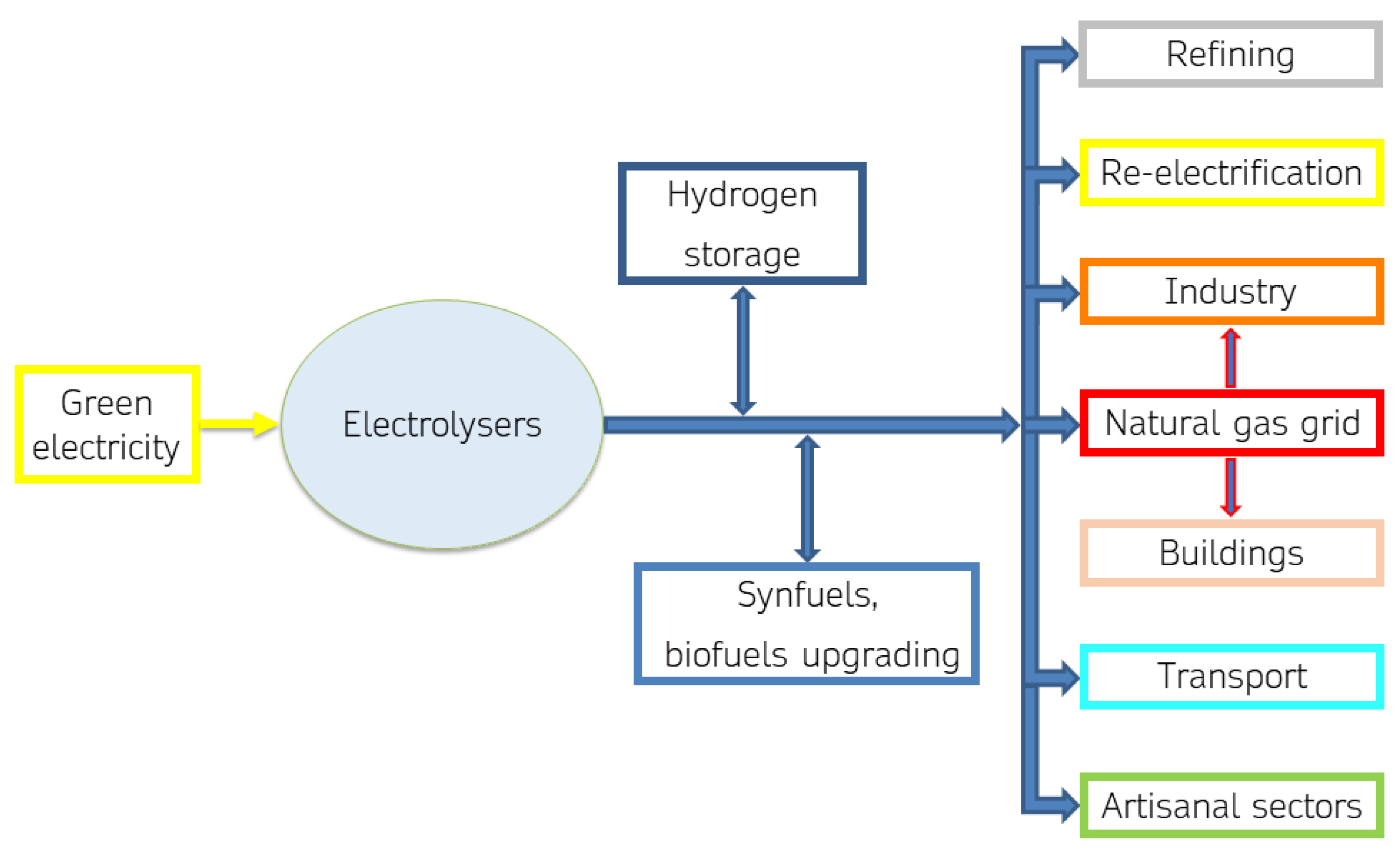
Green hydrogen has an important potential in the process of scaling up renewable energy sources. Electrolysis is a key technology for integrating renewable energy sources into various sectors. It serves as an energy storage solution, enabling the utilization of surplus renewable energy during peak production times. Electrolysis-produced hydrogen finds applications in various sectors, including transportation, industry, and energy storage solutions for grid stabilization. Green hydrogen can play a key role in the energy transition by helping to meet industrial and civil demand for heat and electricity, integrate renewable energy sources into the electricity system, make natural gas infrastructure more sustainable, and decarbonize the transport sector, as shown in
Figure 1.
A small-scale market for electrolytic H2 production has been established in handicrafts, such as gold working. Larger scale production can have leading end-uses in re-electrification, the transport sector, and industry.
In re-electrification, electrolytic hydrogen plays a crucial role by enabling large-scale power production through fuel cells, engines, or turbines. This power can be fed back into the grid to balance demand and generation, making it essential for integrating renewable energy sources. Electrolytic hydrogen serves as a key energy carrier, supporting the integration of variable renewables and providing long-term energy storage solutions spanning days, weeks, or months. Its significance is highlighted in decarbonizing energy-intensive sectors like heavy transport and challenging industries.
Electrolyzers are already in use for refueling stations, making hydrogen a viable option for various vehicles, especially in heavy-duty transport. Additionally, hydrogen serves as raw material in several industries, emphasizing the need for its production from low-carbon sources, such as renewable energy, to achieve decarbonization. Industrial experimentation of hydrogen integration in the productive processes as feedstock, reducing agent, or/and alternative fuel in burners is underway.
Hydrogen has the highest mass heating value among fuels, and an invaluable decarbonization potential [
14] since its combustion generates no carbon dioxide emissions. Green hydrogen can also be used as a renewable energy storage system, linked to the electrification of the processes maximizing the use of green energy from RES. Industrial activities already using hydrogen as a feedstock or/and process agent are favored for electrolytic H
2 integration in their productive processes, because security and safety protocols about hydrogen use are known and managed. Furthermore, gradual decarbonization of the natural gas (ng) infrastructure could take place by injection of increasing percentages of green hydrogen or synthetic methane in the transmission natural gas grid; experimentation with up to 10% in volume of hydrogen are ongoing.
In the iron and steel industry, hydrogen blending in blast furnaces and hydrogen-based direct reduced iron processes are proposed. In the industry of chemicals, electrolysis using variable renewable electricity for ammonia production is between demonstration and market uptake, and in demonstration phase for methanol. Hydrogen’s use for cement kiln blending is in large prototyping. For re-electrification, H2 blending in gas turbines and high-temperature fuel cells is being taken up in the market. Hydrogen refueling stations and hydrogen fuel cells for light- and heavy-duty road transport are being taken up in the market: internal combustion engines for light-duty road transport are also proposed but with less convincing perspectives, while hydrogen fuel cells for shipping and rail applications are between demonstration and market uptake.
Growth scenarios in the energy sector are notoriously unpredictable, often influenced by nonlinear trends or sudden technological advancements. Nonetheless, hydrogen’s impact on energy systems is expected to significantly contribute to the energy transition [
1,
3]. We can say that in 2022, global hydrogen production grew by 2–3% to reach 95 Mtonnes, but low-emission H
2 was about 0.7% (less than 1 Mtonne) of the global production, almost all from fossil fuels. The rate of growth of hydrogen production in the last three years is not particularly remarkable, if according to the data diffused in [
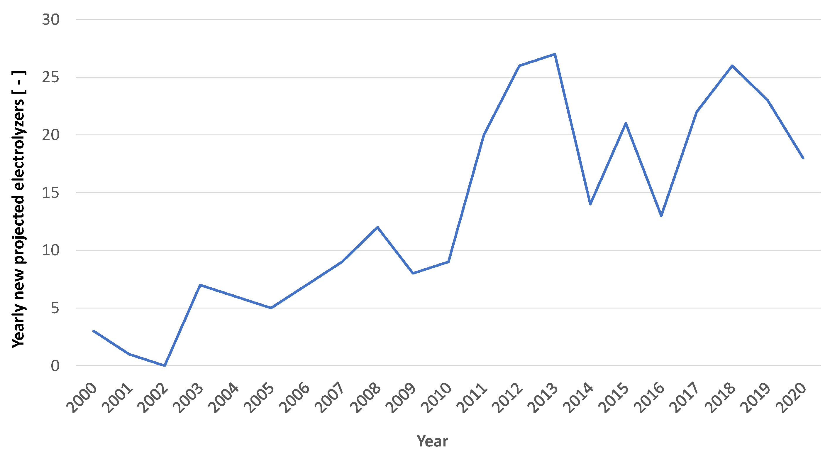
1], the production in 2020 was of about 6 Mtonnes (from 89 Mtonnes in 2020 to 95 Mtonnes in 2022), with a rate of growth of less than 7%. Only a small part of the generated hydrogen is produced through electrolysis. In fact, the installed capacity of electrolyzers is currently quite limited. Globally, as depicted in
Figure 2 and
Figure 3, compiled by the authors based on data provided by the IEA in [
4], the installation of electrolyzers, which began in the early 2000s, has never really taken off and a meaningful increase in power installed can only be observed after 2020.
Electrolysis capacity for hydrogen production has been growing in the past few years; in 2022, installed capacity grew by more than 20%, with about 130 MW of new capacity entering operation in 2022 [
3]. If we consider the data from the IEA, appropriately reanalyzed, it can be estimated that the installed capacity of electrolyzers, assuming all those planned by the year 2020 are operational, would be just under 250 MW [
4]. Certainly, with the projects already planned, the designed capacity could be an order of magnitude higher. However, many of these projects will be completed in 4–5 years, so significant levels are still a distant prospect for the moment.
According to [
4], in 2023, the world’s largest high-temperature electrolyzer was installed in the Netherlands as part of the MultiPLHY project. This 2.5 MW electrolyzer, integrated into refinery processes, produces over 60 kg
H2/h using electricity from dedicated renewable energy sources. Additionally, in 2021, Hydrogen Lab Leuna in Germany inaugurated a 1 MW high-temperature electrolyzer connected directly to the local chemical industry’s pipeline for methanol production, powered by wind energy systems for green H
2 production [
4]. Numerous demonstrative projects have been developed or are ongoing in the world [
1,
15], e.g., hydrogen valleys, in which the electrolytic production of H
2 is integrated with renewable energy sources, especially wind and solar. Green H
2 needs the guarantee of green electricity supply by a dedicated RES plant or a renewable energy mix from the electrical grid.
3. Fundamentals of Electrolysis
In electrolysis, electricity splits water (H2O) into hydrogen (H2) and oxygen (O2) by passing a current through electrodes in a closed system. It includes cells, electrical components, and additional features. Energy consumption depends on technology and conditions. Various electrolysis technologies exist, including low-temperature (ALK, PEM, AEM) and high-temperature (SO) options, each with specific advantages. Ongoing research aims to improve their efficiency, durability, and cost-effectiveness for wider adoption in hydrogen production. The next subsections delve into electrolytic cell physics and stack-level electrolyzer analysis.
3.1. Electrolytic Cell Physics
Examining water electrolysis from a chemical–physical perspective may seem straightforward given the extensive literature available in university textbooks and in several scientific papers. However, the simplicity diminishes when considering the intricacies. The fundamental challenge lies in reducing the energy required to produce a unit of hydrogen mass under specific operational conditions.
Electrolysis is chemically described as the splitting reaction of the liquid water molecule. The enthalpy change in standard conditions (ΔH°) of the reverse reaction of high-temperature electrolysis, the H2 combustion, corresponds to the lower calorific value (LHV) of hydrogen, about 33.3 kWh/kg. Water electrolysis represents a nonspontaneous process, characterized by a significantly positive change in free energy (ΔG). For a process at constant temperature, the alteration in the system’s free energy equals the disparity between the enthalpy change and the product of the absolute temperature and the entropy change (T∙ΔS). ΔG signifies the electrical energy requirement in the electrolytic process, while T∙ΔS indicates the thermal energy demand, and ΔH represents the overall energy needed. Under standard conditions, the electrical energy demand (ΔG°) for liquid water electrolysis stands at 32.7 kWh per kg of hydrogen, whereas steam electrolysis necessitates of 31.5 kWh/kgH2.
These values represent lower limits for quantifying the energy expended in the electrolysis process. This preliminary analysis demonstrates how intrinsic advantages can exist in high-temperature electrolysis, although it still requires additional energy to sustain the process and solving of additional technical problems to maintain the required temperature. The input electricity is determined by the current flowing through the electrolytic cell and the voltage applied. The relationship is given by Ohm’s law: voltage = current × resistance. The power consumption is then calculated as the product of voltage and current. When the electrolytic process occurs under constant temperature and pressure, the difference in electrode potential results in reversible cell voltage (Urev). For liquid water electrolysis, Urev is 1.23 V, and for steam electrolysis, it is 1.18 V, calculated from the standard free-energy change. In real-world scenarios, the cell voltage is always higher than Urev due to the irreversibilities in the actual electrolytic process.
These efficiency losses result in higher voltage requirements (overpotentials, η
∨) for water electrolysis compared to the reversible scenario, as indicated in Equation (1):
In the equation, η
∨act represents the activation overpotential, η
∨ohm the ohmic overpotential, and η
∨conc denotes the concentration or diffusion overpotential. Activation overpotential is linked to the activation energy of reactions and can be mitigated by catalysts and higher operational temperatures. Ohmic overpotential results from electrical, ionic, and contact resistances within the electrolytic cell, influenced by current density, cell materials, design, and temperature. Concentration overpotential, η
∨conc, is tied to mass transport challenges, particularly at high current densities, where slow removal of H
2 and O
2 leads to increased concentration, hampering reaction kinetics. It is accurate to say that the combination of the various overpotentials leads to an increase in energy consumption for electrolysis. Reducing these overpotentials through various means is a focus of research to enhance the efficiency of electrolysis for hydrogen production. Beyond, the operating temperature, pressure, current density, and electrolyzer configuration and materials influence the performance of the electrolysis process, as explored in
Section 4.
3.2. Electrolyzer Analysis at Stack Level
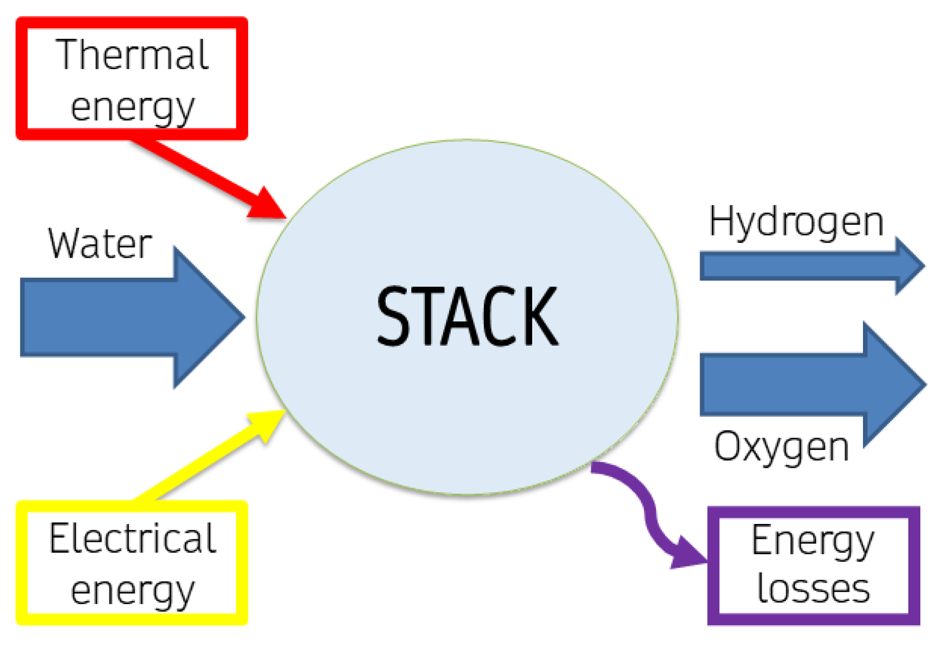
The individual cell, while significant, does not fully represent the complexity of a stack, which comprises multiple cells operating in tandem. Understanding the behavior and efficiency of this stack is paramount, as it reflects the operational dynamics of the electrolyzer system, as depicted in
Figure 4.
Additional losses at the stack level should be taken into account. Considering an electrolytic stack, a mass balance can be written as in Equations (2) and (3), in mol, or Equation (4), in mass:
and by respective molar masses and Equation (4), per kg of hydrogen produced, the mass balance results as follows:
The electrical power in input to an electrolytic cell (W
cell) is equal to the product of the operational cell voltage (U
cell) and the electrical current (I); thus, by Equation (1) it can be described as in Equation (6):
where W
irr is the electrical power due to the various irreversibilities. In commercialized stacks, electrolytic cells are assembled in series; thus, Equations (7) and (8) characterize the real stack voltage, U
stack, and the electrical current input to the stack, I
stack:
with N as the number of electrolytic cells in the stack.
Therefore, the electrical power in input to the stack, W
stack, can be defined by:
The irreversibilities due to the cells’ assembly resulting as thermal power can be defined as:
and the generated irreversible thermal power, Q
gen, can be evaluated by:
where a part of the thermal power generated by the process irreversibilities satisfy the thermal energy demand (T∙ΔS), in the unit time, of the WE reaction (z = 2 is the number of moles of electrons, e
−, transferred per mole of hydrogen in the overall redox equation, and F = 96,485.3 C/mol
e− [
16] is the Faraday constant).
Beyond the electrochemical description, the essence of electrolysis lies in the need for energy input, primarily electrical and sometimes thermal. The minimum theoretical values, as identified in the previously discussed model, are often far from being achieved.
The energy required for electrolysis is higher than the theoretical minimum due to various inefficiencies and losses inherent in the electrolysis process. Several factors contribute to this energy loss:
- (a)
Overpotentials: The actual voltage required for electrolysis is higher than the theoretical minimum. This additional voltage is needed to overcome various resistances within the electrolytic cell, including activation overpotential, concentration overpotential, and ohmic overpotential.
- (b)
Irreversibilities: Electrolysis is not a perfectly reversible process, and there are inherent irreversibilities at the electrode–electrolyte interfaces. These irreversibilities result in additional energy losses during the cell’s lifetime.
- (c)
Heat losses: Electrolysis processes may generate heat, and if this heat is not effectively managed or utilized, represents an energy loss.
- (d)
Cell design and materials: The choice of materials, design of electrodes, and the type of electrolyte can influence the efficiency of the electrolytic cell. Inefficiencies in these components can contribute to higher energy consumption.
- (e)
Electrolyte conductivity: The ionic conductivity of the electrolyte affects the ohmic losses in the cell. If the electrolyte has lower conductivity, more energy is required to drive the current through the cell.
- (f)
Transport losses: The movement of ions within the membrane result in additional losses during the cell’s lifetime.
Efforts in research and development are focused on mitigating these losses and improving the efficiency of electrolysis technologies. Advances in materials, cell design, and operating conditions aim to reduce overpotential and other inefficiencies, making electrolysis more energy-efficient over time.
4. Electrolysis: The Main Technologies and the Relevant Differences
A general classification of electrolysis technologies can be carried out by the operating temperature and the ion transport medium (electrolyte) employed. Technologies such as alkaline (ALK), proton exchange membrane (PEM) and anion exchange membrane (AEM) electrolysis have operating temperatures in the range of 50–80 °C. High-temperature technologies like solid oxide (SO) cells, molten carbonate (MC) cells, and proton conductive cells (PCC) typically work at temperatures in the range 500–1000 °C.
Low-temperature WE technologies employ a basic ionic transport medium, such as a concentrated solution of hydroxide in ALK electrolysis, or an acid medium, such as a solid polymer electrolyte, in PEM electrolyzers. In AEM technology, both a polymeric membrane and an aqueous solution of hydroxide (a few percentage points by weight) are used, trying to combine the advantages of both technologies. In SO electrolysis, the main high-temperature technology, oxygen ions are responsible for the ionic transport and ceramic membranes are utilized. ALK and PEM electrolysis technologies are indeed commercially available and widely used for hydrogen production. These technologies have been in commercial use for several years and are considered mature and established. SO and AEM electrolysis technologies, on the other hand, are still considered emerging or maturing technologies. While there has been significant research and development in these areas, they are not as widely commercialized as ALK and PEM technologies.
4.1. ALK Electrolysis
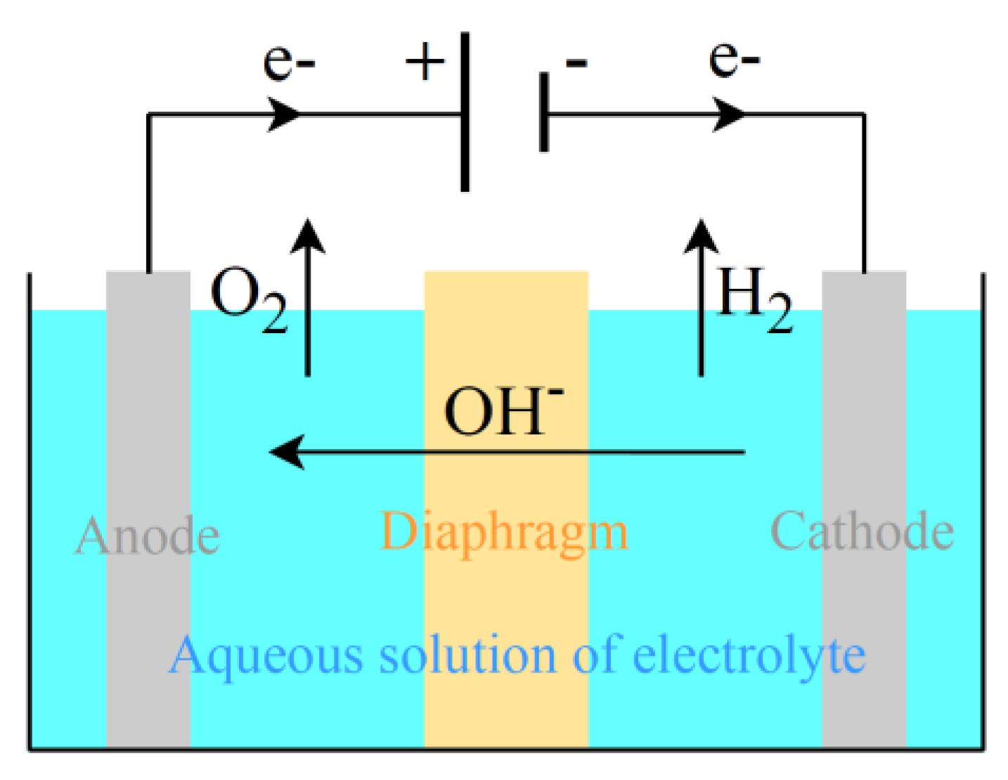
Alkaline WE is the more mature technology, with a long history of deployment in the chlor-alkali industry. For an ALK electrolysis cell, as seen in
Figure 5, the half-cell reactions at the electrodes are the reduction half-reaction at the cathode, Equation (12), and the oxidation half-reaction at the anode, Equation (13):
where the overall reaction is liquid water electrolysis. The reduction reaction of H
2O to H
2 happens in the cathode, generating hydroxyl ions (OH
−); the OH
− ions move toward the anode where they donate their electrons and oxygen is produced. About the potential difference between the electrodes in standard conditions, U°
cathode is 0.83 V and U°
anode is 0.40 V [
16]; thus, U°
rev equals 1.23 V, as calculated by the standard free-energy change value of liquid water electrolysis.
The main components of an ALK electrolysis cell (
Figure 5) are two electrodes, an aqueous solution of an inert strong electrolyte (usually potassium hydroxide, KOH, or sodium hydroxide, NaOH), and a porous medium (diaphragm) as the separator of the anode and cathode chambers. Electrocatalysts are usually employed, e.g., nickel foam sprayed with platinum. The diaphragm is not perfectly impermeable: at low current densities, the cross-contamination phenomenon (crossover) could occur, i.e., some of the gases at the ends of the diaphragm could pass through it, implying explosion risk. The crossover in alkaline cells implies the need for hydrogen purification (deoxygenation by pressure swing adsorption). If coupling with nonstationary power sources, a lower limit to current density is needed (around 20% of rated power). An interesting review on the topic of alkaline electrolysis and the connection with renewables is reported in [
17].
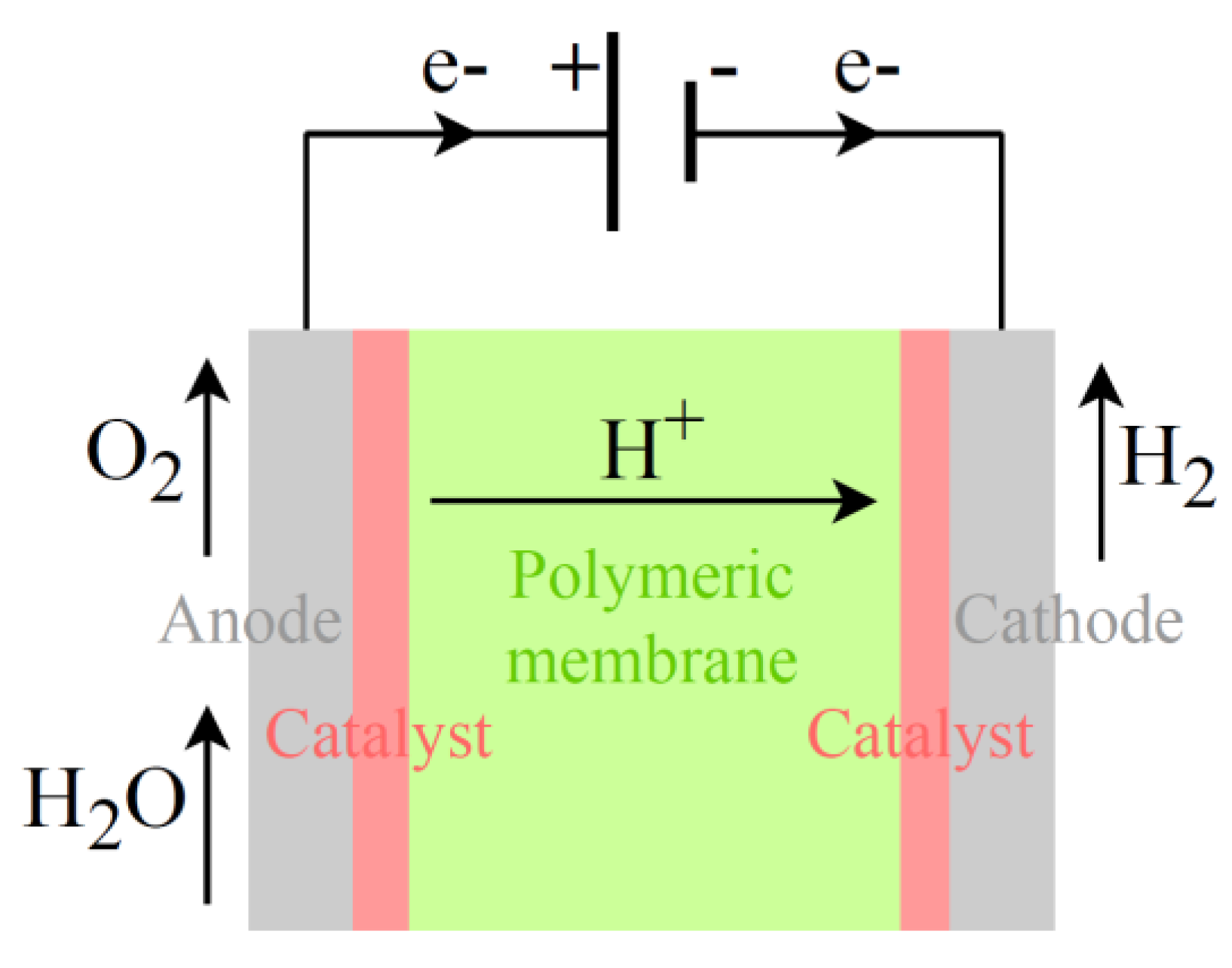
4.2. PEM Electrolysis
In PEM electrolysis,
Figure 6, the two half-reactions, respectively, at the cathode and anode, are described by Equations (14) and (15):
In standard conditions, U°
cathode is 0 V and U°
anode is 1.23 V [
16]; thus, U°
rev equals 1.23 V (as calculated by ∆G° of liquid water electrolysis in
Section 3.1).
In a PEM electrolysis cell (
Figure 6), a polymeric membrane acts as the electrolyte and separator, allowing for only proton ion (H
+) transport from the anode to the cathode. Platinum group metals (usually iridium and platinum) are used as catalysts to accelerate the splitting process. Scarce materials can represent a barrier to electrolyzers’ scaling up. PEM water electrolysis is comprehensively highlighted and discussed in several reviews available in the literature, such as [
18,
19].
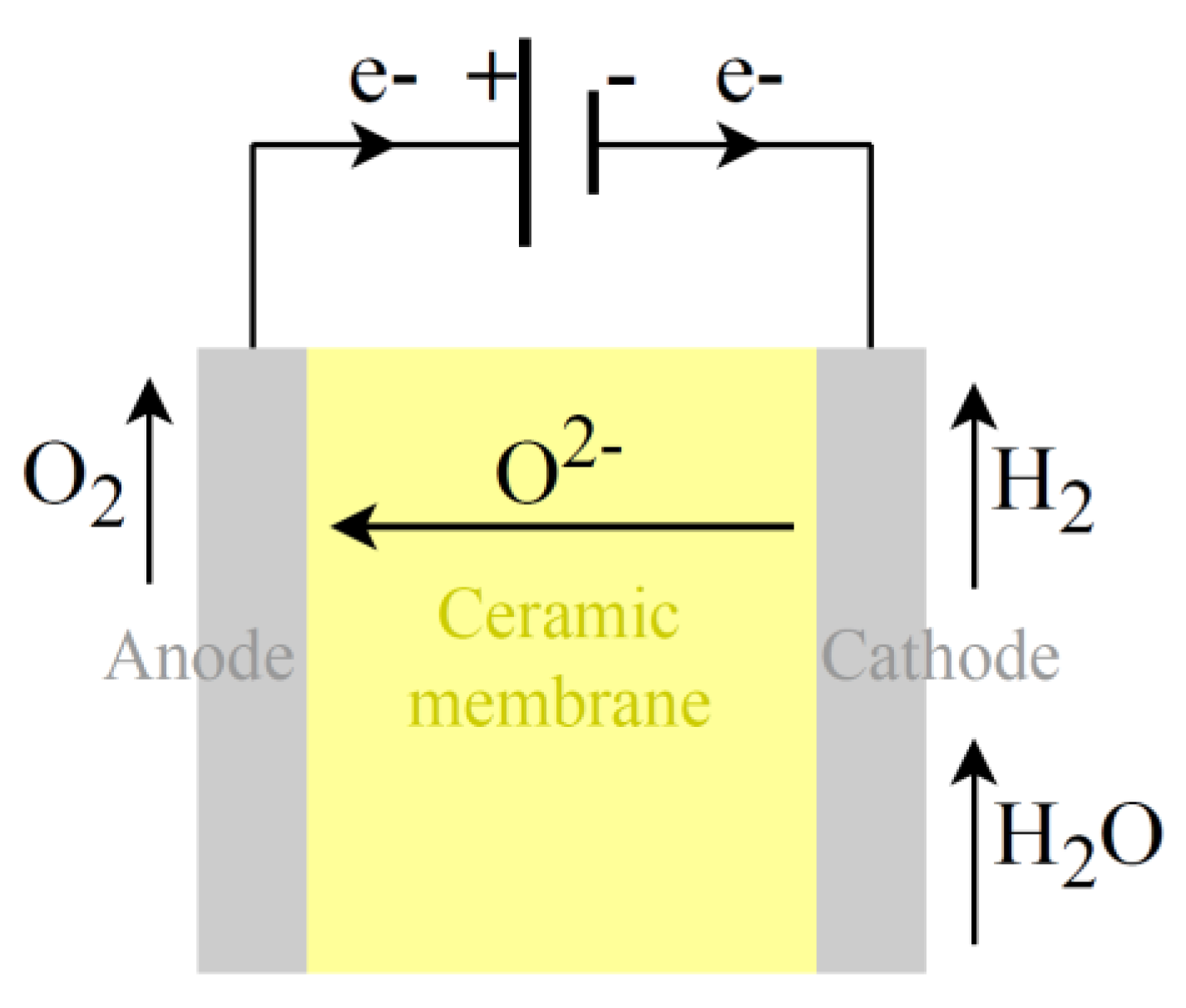
4.3. SO Electrolysis
Increasing temperature in electrolysis can lead to significant reductions in electrical consumption but introduce the use of thermal energy. High-temperature electrolysis, such as by using SO cells, schematically represented in
Figure 7, is a promising approach that utilizes elevated temperatures, typically above 600 °C, often in the range of 800 to 1000 °C. The reduction half-reaction at the cathode, Equation (16), and the oxidation half-reaction at the anode, Equation (17), are written as follows:
where the overall reaction is steam electrolysis. At 1000 K, U
rev is equal to 0.94 V [
12], a much smaller value than U°
rev (1.18 V) calculated in
Section 3.1, thanks to the strong reduction in electricity demand (∆G) as the temperature increases.
In SO electrolysis (
Figure 7), a ceramic membrane is used (usually YSZ, i.e., yttria-stabilized zirconia), which acts as the electrolyte and separator, allowing only for oxygen ion (O
2−) transport from the cathode to the anode. A preheated air flow is normally introduced through the anode. This air stream is used to control the temperature and guarantee the correct temperature distribution inside the stack, thus avoiding a degradation increase. By leveraging the benefits of elevated temperatures, SO electrolyzers look promising in reducing electricity consumption, making this an area of active research. However, solid oxide electrolysis needs process heat and steam input, which should be considered in an evaluation of First Law efficiency and system performance. If industrial waste heat or heat from RES is used as process heat, overall efficiency improvement is possible.
Thermal control is indeed a significant concern in solid oxide electrolyzers (SO electrolyzers). Maintaining precise operational temperatures is crucial for the efficiency and stability of SO electrolyzers. These devices rely on high operating temperatures, typically around 700–900 °C, for the solid oxide electrolyte to conduct ions effectively. Accurate thermal management is essential to prevent overheating, ensure uniform temperature distribution across the electrolyzer cells, and avoid thermal stress on the materials, which can impact the electrolyzer’s performance and lifespan. Additionally, efficient thermal control is vital for safety reasons, as high temperatures can pose risks if not properly managed. Developing effective thermal management systems is a key area of research and innovation in the field of SO electrolysis. Hauch et al. [
20] summarized the latest progress in research and development of alternative and innovative materials for SO electrolysis.
4.4. The Operational Performance of Electrolyzers
The operative conditions and the electrodes, ion transport medium, and catalysts employed characterize the performance of the various electrolyzers. A lot of research on electrolytic cells’ performance has been conducted to increase the efficiency of electrolyzers [
5,
6,
7,
8,
9,
10,
11,
12] and WE plants [
13]. Electrical efficiency losses can be identified as a function of many variables, as shown in
Table 1.
The thermal energy required is fundamental too, from warming up to heat requirements during electrolyzers’ operation, through components’ heat transfer properties and heat dissipation or usage. In the literature, the ohmic losses have been identified as predominant both for low- and high-temperature technologies in the range of operational current densities. Research must still be conducted to identify the configurations, materials, and operating conditions that maximize hydrogen production while minimizing the associated energy consumption of each technology. The main characteristics, traced in the literature and by market analysis, of the leading electrolysis technologies are provided in
Table 2.
The main limits and positive characteristics of each technology are reported in
Table 3. ALK technology’s advantage is the condensation recovery, which implies a lower water requirement; on the other hand, corrosive electrolytes are employed, low current densities entail bigger volumes, and a hydrogen purification stage is necessary due to the cross-contamination phenomenon. PEM electrolyzers are interesting for specific utilization; for example, they can harness cooling system heat. Unfortunately, they incur higher costs due to components (catalysts, membranes) and operation (e.g., water use).
SO electrolyzers boast superior electrical efficiency and reversibility. However, they require high-temperature steam and thermal sources (even if it would be possible to use industrial waste heat or heat from RESs as process heat), warmup times are long because high operational temperatures must be reached, and the useful life is limited due to thermal cycles. Selecting the ideal WE technology depends on specific operating conditions set by electricity and heat sources, and hydrogen end-uses. SO electrolysis, when fully developed, appears optimal for industrial use, proven ALK technology is suitable for re-electrification or for developing the idea of promoting hydrogen injection into natural gas grids, while smaller PEM electrolyzers could find applicability in the transport and civil sectors. Hydrogen still faces numerous limitations, and upon closer examination, data in certain application areas show negligible levels. Certainly, it is accurate to assert that electrolysis technology still faces limitations, as outlined in
Table 3. This highlights the existing challenges and areas that require further development and innovation. The estimated cost of green hydrogen ranges from USD 3 to USD 6 per kilogram of produced H
2, while ongoing advancements aim to reduce it to 2 USD/kg
H2 or lower [
21,
22].
The cost of hydrogen produced by electrolysis is indeed influenced significantly by the cost of the electrolyzer and the useful life of the electrolyzer. These factors contribute to both the capital costs (initial investment) and operational costs (maintenance, electricity, etc.) associated with hydrogen production.
The costs of electrolysis can vary depending on the technology used, the scale of the electrolyzer, and other factors. Here are some general estimates for the capital costs of different technologies: ALK electrolysis: around USD 200 to USD 600 per kW; PEM electrolysis: USD 500 to USD 1000 per kW; SO electrolysis: USD 1000 to USD 3000 per kW.
These values are indicative and may vary based on specific project conditions, technological advancements, and economies of scale. Additionally, operational costs, maintenance, and other factors contribute to the overall cost of hydrogen production.
For the most accurate and up-to-date cost information, it is recommended to refer to recent industry reports, project-specific data, or consult with experts in the field. The costs associated with electrolysis can change over time as technologies advance and market dynamics evolve. Concerning the useful life of electrolyzers, in the literature, it is possible to find estimates on the useful life of ALK and PEM electrolyzers longer than those reported in
Table 3 (e.g., 60,000–95,000 h for ALK, 50,000–80,000 h for PEM [
5,
21]); however, tests performed to predict stacks’ long-term performance (e.g., according to accelerated stress test methodology) are around a few thousand hours, extrapolating performance data up to 40,000 h. Component lifetime is evaluated in the order of some to several thousands of hours [
23,
24]. SO electrolyzers’ lifespan is still in research, nowadays estimated to be at most 10,000–20,000 h [
5,
21].
4.5. The Actual Problems Connected to Electrolysis and Electrolyzer Development
The recent advancements in electrolysis demand continuous research to enhance efficiency, scalability, and cost-effectiveness in hydrogen production.
Table 4 provides a summary of the main research activities and objectives in water electrolysis.
Existing challenges include integrating electrolysis with renewable energy sources and energy grids while ensuring stability. Current data, often from commercial sources, lack standardized methodologies, highlighting the need for universal testing protocols.
The development of hydrogen production through water electrolysis necessitates a well-structured system of regulations and certification, addressing challenges in standardization, data reliability, and performance measurement methodologies. ISO 22734:2019(E) is a document intended to be used for certification purposes of ALK, PEM, and AEM electrolyzers for industrial, commercial, and residential applications [
25]. The ISO Technical Committee ISO/TC 197 is developing standards for hydrogen technologies; in particular, the Working Group ISO/TC 197/WG 34 deals with electrolyzers’ test protocols and safety requirements. System equipment requirements, test methods, and the ongoing work of ISO/TC 197/WG 34 emphasize the necessity for standardized methods to ensure accurate performance evaluation in electrolysis. Beyond the established successes, it meticulously scrutinizes the intricate challenges tied to seamlessly integrating electrolysis systems with existing energy grids and renewable sources. As we explore the intersection of energy analysis and electrolysis, we confront the pressing issue of scaling up.
This multifaceted investigation navigates the complexities of amplifying electrolysis capacities, ensuring not only increased production efficiency but also harmonious integration within larger energy infrastructures. By delving into these critical areas, this research aims to illuminate pathways for a sustainable and efficient hydrogen production future, based on general integration with renewable energy. In the next section, we attempt to investigate this further problem. The challenges and limitations of each water electrolysis (WE) technology can be addressed through targeted solutions. For instance, ALK electrolysis faces issues like cross-contamination, necessitating efficient hydrogen purification methods. The large volume of ALK electrolyzers, due to low current densities, becomes less problematic with concentrated production. PEM electrolysis grapples with costly catalysts and membranes, demanding ongoing research into cost-effective yet high-performance materials. SO electrolysis requires effective thermal management due to steam and high-temperature heat needs. Advancements in durability and cost reduction of membranes can enhance SO electrolysis success. A final remark concerns the environmental impact of the various electrolysis technologies can be evaluated by the corresponding carbon dioxide-equivalent (CO
2-eq) emissions per kg of produced hydrogen, thus the corresponding global warming potential (GWP). Gerloff [
26] conducted a comparative lifecycle assessment analysis for ALK, PEM, and SO water electrolysis for a system size of 1 MW: SO technology seems to have the lowest GWP; instead, ALK and PEM electrolysis appear similar in terms of kg
CO2-eq per kg of produced H
2. But it is a quite complex task.
5. Energy Analysis of Electrolysis: Commercial State-of-the-Art and the Additional Problems Connected with Energy System Integration and Scaling Up
Electrolysis is often measured in terms of energy intensity, representing the energy required to produce a unit of hydrogen (typically in kilowatt-hours per kilogram, kWh/kg). Typically, real-world electrical energy demand for hydrogen production via water electrolysis falls in the range of 50 to 60 kWh per kg of hydrogen produced. However, ongoing research and advancements in electrolysis technologies aim to reduce these losses, bringing the actual energy demand closer to the theoretical minimum.
Data from the literature and the market, summarized in
Table 5, show that actual energy consumption for hydrogen production exceeds theoretical values. Electrolyzers with nominal powers above 100 kW demonstrate specific electricity consumption (ASEC) averaging 55–60 kWh/kg for low-temperature systems and 40–42 kWh/kg for high-temperature ones (in this case, no market data are available). These figures underscore efficiency losses and higher energy demands in practical hydrogen production.
The producible hydrogen per MW of installed electrolysis capacity is about 18 kg/h for low-temperature multi-MW scale electrolyzers; the solid oxide technology aims for values greater than 20 kg/h per installed MW. The energy needs for hydrogen production vary with electrolyzer size. Evaluating energy requirements accurately requires understanding the electrolyzer’s specific features and scale. Advancements in low- and high-temperature electrolysis, coupled with optimizations, can enhance energy efficiency, lowering energy consumption per unit mass of hydrogen. The performances of an electrolyzer can be evaluated by means of the First Law efficiency as:
where the useful effect of the process is evaluated through hydrogen (mass) lower calorific value, LHV
H2, and (mass) flow rate, ṁ
H2, and W is the electrical power and Q is the thermal power in input to the electrolyzer. Considering only electricity consumption data available in the literature and commercial catalogues, efficiency results in around 60% for low-temperature electrolyzers and about 80% for high-temperature electrolyzers, with the current ASECs of large-scale electrolyzers identified in
Table 5. From the declared electricity consumption of electrolyzers, it is possible to define an electrical efficiency, η
el, as the ratio of the electricity demand of the electrolytic process and the average specific electricity consumption of the electrolyzer [
2]:
By evaluating the electricity demand at standard conditions (ΔG°) as a fixed comparison term for both low- and high-temperature electrolysis, and using ASECs from
Table 5, electrical efficiency stands at approximately 57% for low-temperature and 77% for high-temperature electrolyzers. The electrical energy demand diminishes steadily with rising temperature and notably above 100 °C. If ΔG were assessed at operating temperature rather than standard conditions, electrical efficiency would be lower, especially for high-temperature electrolyzers. Key data and results are summarized in
Table 6.
In low-temperature electrolyzers like ALK, PEM, and AEM, energy consumption of about 55–60 kWh is expected per kg of hydrogen produced, resulting in a 40% energy loss. Elevated temperatures enhance electrolysis reactions, accelerating kinetics and increasing hydrogen production rates. This reduces overpotentials, lowering the electrical energy required and minimizing electricity consumption. However, high-temperature electrolysis presents challenges, including material compatibility, thermal management, and system integration. Proper materials for cell components and effective heat transfer methods are vital to achieve optimal operating conditions. Addressing these technical aspects is crucial to unlock the full potential of high-temperature electrolysis.
5.1. System Level and Integration Problem
In
Section 3 and
Section 4, the operation of the different electrolyzers is summarized. Nevertheless, the development of electrolyzers necessitates a broader assessment of their operation within a clearly defined plant context. Focusing on the electrolyzer only is inadequate for comprehensively addressing the energy dynamics. Auxiliary operations associated with the system are frequently overlooked, and, in certain instances, they contribute to increased energy consumption. This is particularly evident in the context of solid oxide (SO) electrolyzers, where assessing the electrolyzer can falsely suggest a reduction in energy use. An electrolysis plant is much more complex than just the single cell or the stack. Its effective operation requires several subsystems that impact the plant’s efficiency, dynamic behavior, and consequently, its flexibility. This interaction requires careful optimization to minimize energy losses.
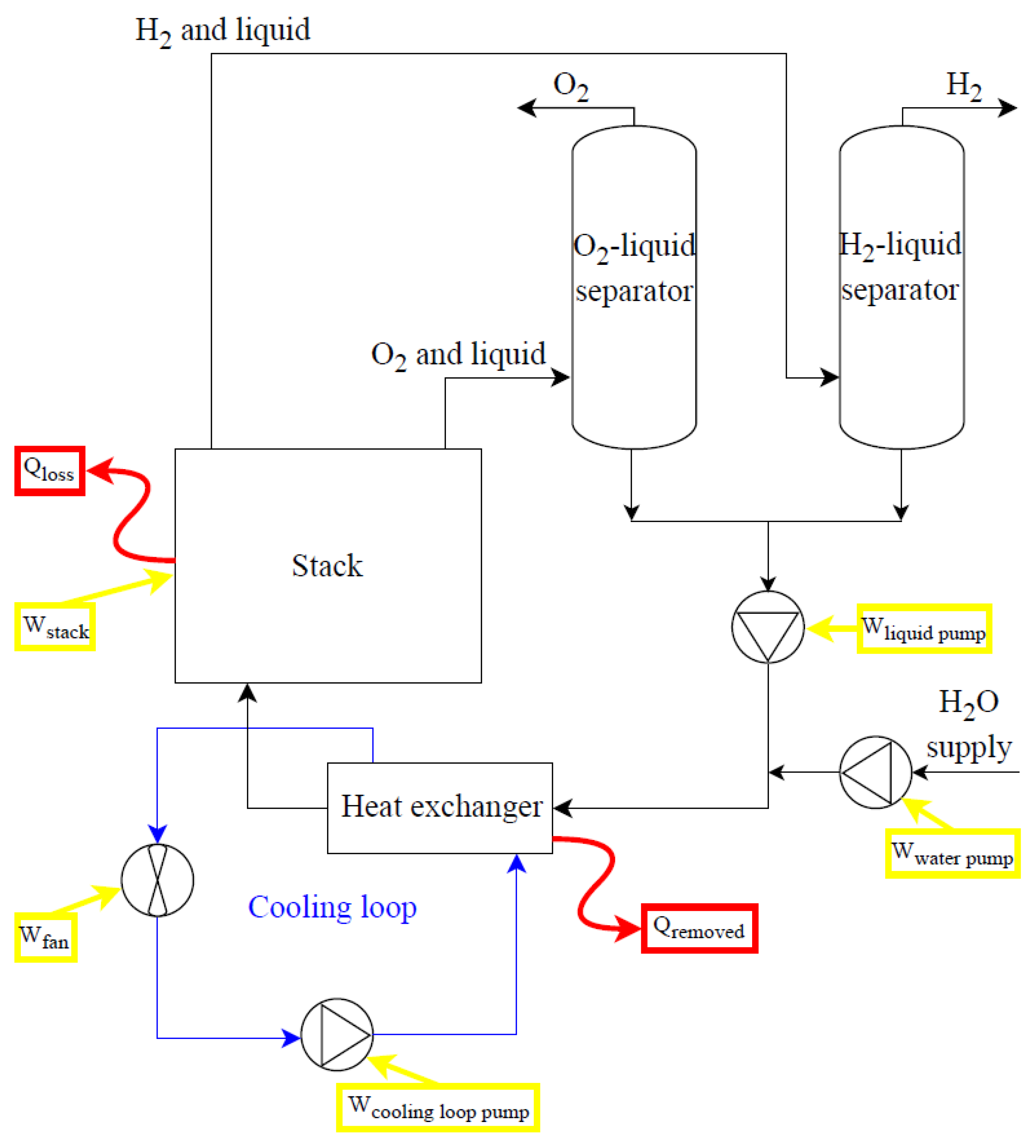
Figure 8 and
Figure 9 provide simplified diagrams of low-temperature (ALK and PEM) and high-temperature (SO) electrolysis systems, respectively. Consideration of auxiliaries’ energy consumption is crucial. These auxiliaries form the balance of plant, accompanying the key components like the stack, deionized water subsystem, power supply, and gas–liquid separation and thermal management subsystems. Considering the case of an ALK electrolysis system (
Figure 8), energy balances can be written as:
where W
pumps is the electrical consumption of water, electrolyte solution, and cooling loop pumps; Q
rem is the thermal power removed by the cooling system to maintain the stack temperature at operating values; and Q
loss is the thermal losses of the stack. In the case of cogeneration purposes, the electrical consumption of the fan and cooling loop pump could be avoided, and the thermal power generated in the stack could be recovered, regarding how it is evaluated for PEM electrolysis systems. Considering SO electrolysis systems (
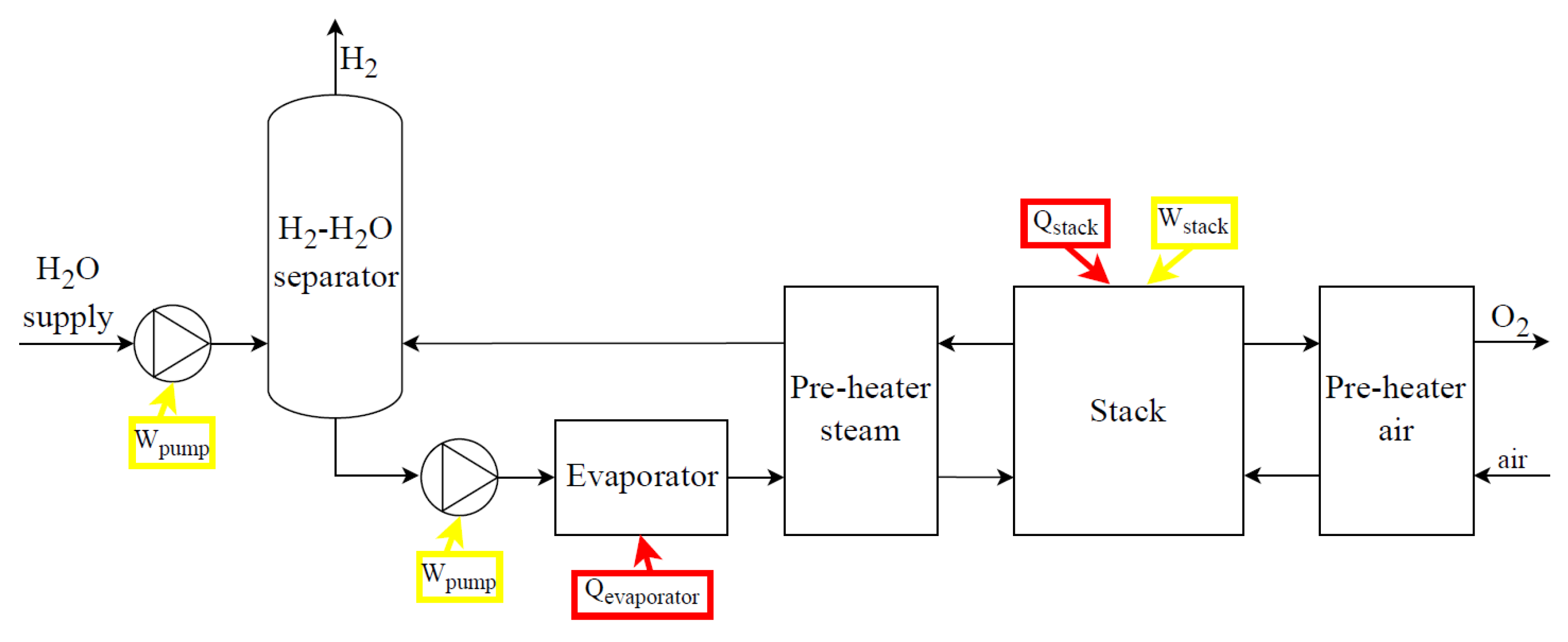
Figure 9), main components are the power supply subsystem, the deionized water subsystem, the steam production subsystem, the subsystem of air supply, the stack and stack heating, the H
2/steam supply unit, the gas–liquid separation unit, and the pressure control and thermal management subsystems.
All electrolysis systems (
Figure 8 and
Figure 9) may require additional elements like drying subsystems (condensate traps, cooling systems, and coalescence/desiccant filters) and purification subsystems (de-oxo reactors) depending on the quality of the hydrogen required; all of them require additional input energy.
5.2. Electrolyzers’ Scaling Up
ALK and PEM electrolyzers of the size of 100 kW are commercially available and already marketed, but larger sizes are needed for massive hydrogen production to meet future demand scenarios for decarbonization, as discussed in
Section 2. MW-size projects are currently in the demonstration phase, and GW-scale projects have been announced for the next years [
1,
15].
Water electrolysis is a modular technology, and electrolyzer manufacturers are evaluating different choices in terms of stack dimensions and number of stacks to connect to reach the MW size. Scaling up of stack components is a difficult challenge for the various electrolysis technologies.
Investigating the electrolyzer literature and the market, it is evident that smaller sizes have higher nominal energy consumption. For large electrolyzers, more performing materials and configurations can be used, since a higher initial capital cost can be compensated by lower operating energy costs in massive hydrogen production. However, cells’ assembly losses are important, and the balance of plant needs to be carefully optimized.
Moreover, advancements in electrolysis technology will lead to the development of large-size electrolyzers, bringing the technology from the megawatt (MW) scale to the gigawatt (GW) scale. The need to increase electrolyzers’ manufacturing capacity is a priority to materially contribute to energy transition by water electrolysis [
21]. For green hydrogen production, electrolyzers’ scaling up travels with RES exploitation’s growth and with H
2 uses’ development.
Adequate strategies, policies, and financial support from the key stakeholders (i.e., governments, industry, and international organizations) are fundamental for the implementation of the entire green hydrogen value chain. International policies and regulations play a crucial role in advancing water electrolysis (WE) technologies. Industrialized nations have national hydrogen strategies, promoting WE adoption across sectors. Policies fostering demand and mitigating investment risks are vital. Supporting domestic manufacturing of hydrogen technologies enhances sustainability. Research, development, and international cooperation are promoted through initiatives like the National Recovery and Resilience Plan (NRPP). Establishing standards, certifications, and regulations is essential for the widespread adoption and consolidation of WE technologies, ensuring performance measurement and workplace safety, as discussed in
Section 4.5.
Manufacturing capacity scaling up and cost reduction are necessary. Technological improvement in terms of electrolyzers’ efficiency and durability are fundamental to reducing the specific cost of the hydrogen produced, decreasing the amount of energy required to produce one unit of hydrogen, and extending the equipment lifetime, thus spreading the cost of the electrolyzer facility over a larger hydrogen production volume. Cost reduction in electrolyzers’ manufacturing and balance of plant could be made possible by economies of scale. Design and manufacturing should be simplified and standardized to allow for industrialization.
5.3. Integration of Electrolyzers and Renewable Energy Sources in the Electrical Energy System
Hydrogen will play a pivotal role in the energy transition only if it successfully facilitates the integration of renewable energy sources. Renewable energy storage is fundamental. Electrochemical storage systems are not well suited if energy needs to be stored for extended periods, such as weeks and months. One of the best solutions for long-term storage of renewable energy is green hydrogen, because of its limited self-discharge rate (leakage and/or permeation) and decoupling of energy rating from the power rating. Green power can be used to produce electrolytic hydrogen when electricity production from new RESs (mainly solar, wind, hydroelectric) is higher than electricity consumption.
However, RES variability and intermittent supply is a problem for electrolyzers, which adapt poorly to sudden load variations (potential problems of corrosion, changes in the internal temperatures, pressure drops, explosive mixture generation) and have better performance at full or high loads. Together with suitable power electronics, batteries’ utilization is probably the best strategy capable of guaranteeing green electricity supply to electrolyzers in the most stable and controlled way possible.
RES low density is a challenge for green hydrogen production too. It is estimated that a large-scale electrolyzer will be able to work around 5000 h/y [
1]. Assuming a WE-specific electricity consumption of 55 kWh/kg, a balance of system typical of large photovoltaic (PV) generation, and an annual specific solar energy equal to 1500 kWh, 250 kW of installed PV peak power could be necessary to produce 1 kg/h of electrolytic hydrogen.
The efficiency of green hydrogen production systems by wind energy or photovoltaic generation and low-temperature electrolysis is estimated to be around 10–12% [
15].
Considering current average efficiencies of photovoltaic modules, charge regulators, batteries, inverters, low-temperature electrolyzers, and balance of plant, an overall efficiency (η
PV+WE) can be evaluated between 8% and 10% as the product of the average efficiency of the photovoltaic generation and the average efficiency of the electrolytic hydrogen production system. Assuming an overall efficiency of around 10%, about 330 kWh of solar energy per kg of H
2 is needed, according to the general indication provided by a kind of extended balance of system efficiency, as in Equation (22):
The topic of integrating hydrogen into energy systems based on intermittent renewable sources, such as photovoltaics (PV), wind, offshore wind, and hydroelectricity, must be approached with great care. It certainly requires improvements, especially concerning electrolysis, but it needs to be evaluated with utmost caution in every aspect.
5.4. Integration of WE with Renewable Energy Sources in a Specific Context: Steel Industrial Sector
A more feasible possibility, although challenging to implement, could be the direct connection between some energy-intensive industrial processes and renewable-based generation facilities (such as photovoltaics) using hydrogen. However, even in this scenario, certain dimensional aspects need to be clear, namely, the high-power demands in these sectors. Let us consider, for illustrative purposes, a specific case—the steel industry—and conduct evaluations referencing specific sites with significant steel plants.
In a recent study, the authors already explored the potential use of hydrogen in the steel industry, which can be employed both as a direct fuel or to innovate the production process through modern technologies, such as the direct reduced iron process [
2]. For example, 60 kg of H
2 generated using low-temperature WE is necessary per ton of steel produced by the hydrogen-based direct reduced iron process (H
2DRI) and electric arc furnace (EAF) process [
2]. The producible hydrogen per MW of installed electrolysis capacity is about 18 kg/h for multi-MW-scale low-temperature electrolyzers; about 3.3 MW of electrolysis capacity would be necessary per ton/h of steel produced using H
2DRI-EAF.
Table 7 provides some qualitative estimations for photovoltaic generation per ton of steel, as produced with the H
2DRI-EAF process utilizing hydrogen generated through low-temperature water electrolysis [
2], in several major steel production sites worldwide. Evaluating the minimum PV surface that would be necessary in some big steel production sites by local hydrogen production, thus the respective global tilted irradiation at the optimum angle [
27], and assuming annual production, 0.2–0.3 m
2 is needed per kg
H2, thus 12–18 m
2/ton
steel. In favored sites, around 0.2 m
2/kg
H2, thus more than 10 km
2/Mtonne
steel, with current process efficiencies, is required: these big numbers are due to low PV + WE efficiency and low energy density of solar source. Indeed, concentrated green hydrogen production is evaluated in greater irradiation sites. While improving all hydrogen processes’ efficiency, green H
2 blending in the direct reduced iron process would need to be evaluated to reduce the iron and steel sector’s emissions.
6. Conclusions
Electrolysis accounts for approximately 0.1% of the world’s hydrogen production while most of the hydrogen is still produced through conventional chemical processes like natural gas reforming. Although electrolysis’s contribution remains marginal, its development has become crucial for green hydrogen production, marking a small step toward industrial decarbonization.
Electrolysis systems are typically 60–65% efficient, meaning they convert 60–65% of the input electrical energy into chemical energy stored in hydrogen gas. On average, low-temperature MW scale electrolyzers need 55–60 kWh of electricity to produce one kilogram of hydrogen. High-temperature electrolysis can be more efficient, and the target is to reduce energy consumption at 40–45 kWh of electricity to produce one kilogram of hydrogen, but it requires steam and process heat input. The producible hydrogen per MW of installed electrolysis capacity is about 18 kg/h for low-temperature multi-MW-scale electrolyzers and about 25 kgH2/h/MWWE for high-temperature ones.
Realistic estimates of ALK and PEM electrolyzers’ lifespan are 10,000–40,000 operational hours. Nowadays, AEM and SO electrolysis devices have a useful lifetime that is shorter. Advanced materials and engineering could extend the lifespan of electrolyzers of each WE technology. Increasing electrolyzers’ useful life can reduce the hydrogen production cost reduction and promote electrolyzers’ scaling up.
The cost of green hydrogen production through electrolysis varies widely based on factors such as electricity prices, electrolyzer efficiency, and scale. The estimated cost ranges from 3–6 USD/kgH2. Ongoing advancements aim to reduce the cost to 2 USD/kgH2 or lower, making green hydrogen more economically competitive.
Research in various areas aimed at increasing the efficiency of electrolysis processes, bringing them as close as possible to theoretical values (around 33 kWh of energy and about 9 kg of water per 1 kg of hydrogen produced), cost reduction of electrolyzers, and prolonging their lifespan (a useful life of 10,000 h seems rather low to justify economic investments) is crucial to positioning hydrogen as a significant player in future energy transition. However, it is essential to recognize that hydrogen is an energy carrier, and the primary challenge remains the energy resource itself. The examples discussed, particularly the integrations between hydrogen and photovoltaics in various contexts, including specific facilities like steel plants, highlight the difficulties and complexity of the challenge ahead. Nevertheless, this study aimed to showcase the ongoing efforts in electrolysis process improvement and the goals set for future research.


