Abstract
Model predictive control (MPC) is an efficient and growing approach to power converter control. This paper proposes an improved and simplified model predictive current control (MPCC) technique for a four-level nested neutral point clamped (4L-NNPC) converter. Conventional MPCC exhibits better performances as compared to the conventional linear control system such as fast dynamic response, consideration of the system constraints, and nonlinearities. However, the application of the conventional model predictive current control (MPCC) approach on complex systems provokes a significant number of calculations, which is the main hurdle to its practical implementation. To fix this flaw, this paper proposes an effective algorithm to shorten the execution time of the conventional MPCC. In this proposed technique, 216 current predictions of the conventional MPCC are skipped and converted into one required voltage vector (RVV) prediction. With this equivalent reference voltage transformation, the calculation burden of MPCC is significantly reduced, while the output performance is not influenced. The results of the simplified MPCC for the 4L-NNPC converter are analyzed and compared with the conventional MPCC. The computational time is reduced by 19.56% using the simplified MPCC, while keeping an approximately similar error of output currents. The switching frequency and total harmonic distortion (THD) of the proposed method are reduced by 8.16% and 0.07%, respectively, as compared to the conventional technique. These results demonstrate the fact that that the performance of a conventional MPCC is enhanced with the proposed MPCC. The proposed algorithm can be applied to several inverter topologies.
1. Introduction
Multilevel converters are preferred candidates in high-power conversion applications such as distributed generation systems, microgrids, and motor drives, used to gain the desired voltage and performance in the medium-voltage range [1]. Multilevel converter topologies are the favored choice to achieve the required high levels of power and voltages. In comparison with a two-level voltage source converter (VSC), the primary characteristics of these arrangements are their effectiveness in decreasing the THD of the ac-side signals, switching the stresses of the rate of change of voltage, switching losses, and diminishing or even removing the interface transformer [2,3,4,5,6].
Optimal control carries out good quality and efficiency in power conversion with the high fidelity of power converters. For instance, to handle common-mode voltages, vibration suppression is used in the power converter to reduce power losses as well as current harmonics and enhance the protection of the system [7,8,9,10,11]. Numerous control techniques are used to control the variables of power converters as presented. Of all of these controls, hysteresis and linear controls with PWM are very familiar and easy to implement [12,13,14]. However, the implantation of modern and more intelligent control methods is feasible with the growth of new fast digital signal processors and microcontrollers. Some modern control techniques are fuzzy logic, sliding mode control, and model predictive control (MPC).
1.1. Motivation and Incitement
Optimal control can be easily employed with the help of MPC for numerous objectives. It has a good attraction in the control system because of its characteristics such as essential decoupling, rapid dynamic response, reactive power compensation, and the easy addition of constraints [15,16,17,18,19,20,21,22,23,24,25,26,27,28,29,30]. The finite control-set model predictive control (FCS-MPC) has grown quickly in the last decade, covering many fields, such as UPS, renewable energy systems, electric grids, multi-level converters, electric drives, etc. [31,32,33,34,35].
1.2. Literature Review and Research Gaps
Nevertheless, there exists a hurdle in the actual implementation of MPC: a smaller interval of control loop time to attain the same performance as conventional control methods [36,37]. Consequently, the permitted time to accomplish the calculations is reduced in such a way that it is impossible to implement conventional MPC on low-speed processors. Furthermore, the volume of calculations will rise with the complexity of the technique, the inclusion of constraints, and the neutral point balancing. To address this problem, different approaches are analyzed to reduce the complexity of the MPC technique [38,39,40].
A conventional MPCC technique of the 4L-NNPC converter is discussed in which the optimum switching state is selected in each control loop cycle [41,42]. For this purpose, 216 current predictions are required for each phase. Due to this calculation burden problem, the MPCC technique becomes impractical in the case of a low-speed processor. On the other hand, the cost of the control technique increases if a high-speed processor is used. In short, the time-consuming calculation burden is the main issue in the practical implementation of the conventional MPCC. So, complexity reduction and simplifying the algorithm approaches to solve the computational time issue are better options than conventional MPCC if the performance of the system is not disturbed.
1.3. Contribution and Paper Organization
The main contribution and novelty of this paper is to shorten the control loop cycle time of the conventional MPCC technique for practical implementation and cost reduction. This is achieved by the following steps:
- Analyze the mathematical model, control set, and the performance of 4L-NNPC converters.
- This analysis is used for developing an algorithm, called simplified MPCC, which converts 216 current predictions calculations of the conventional MPCC of 4L-NNPC into one required voltage vector (RVV) calculation for each phase.
- After implementation of this algorithm, the calculation burden is significantly reduced (216 × 3 to 1 × 3 calculations) and the performance of the system is not disturbed.
- Consequently, this simplified MPCC technique is much better than the conventional MPCC method, and it contributes to obtaining low-cost and high-performance 4L-NNPC for high-power medium voltage applications.
The rest of the paper consists of five sections. In Section 2, a mathematical model of the 4L-NNPC converter is discussed. The conventional MPCC technique for 4L-NNPC is reviewed in Section 3. The proposed simplified MPCC technique is described in Section 4. In Section 5, both conventional and simplified techniques are implemented and compared. The conclusion of the paper is given in Section 6.
2. Four-Level Nested Neutral Point Clamped (4-L NNPC) Converter
4L-NNPC Converter [42], as given in Figure 1, is explained for medium-voltage high-power applications. It has a DC voltage source and three legs for three phases; each leg consists of six switches, two diodes, and two flying capacitors. In contrast to the classic four-level converter topologies, the suggested 4L-NNPC converter topology has a smaller number of elements.
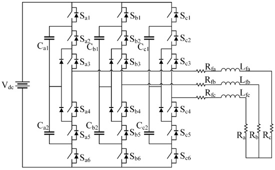
Figure 1.
Four-Level Nested Neutral Point Clamped Converter.
It is designed by combining FC and NPC converters, which generate four-level voltages at the output. The capacitors and , are charged to to guarantee equally spaced voltage levels. From all 64 possible switching combinations, as for six switches in one leg, only six switching states, as shown in Table 1, are chosen to produce four levels of voltage. In this converter, all switches are identically stressed as . The redundancy in switch combinations is another benefit of the proposed converter to create higher levels. For instance, there are two extra switching combinations to create voltage levels of and .

Table 1.
Switching states of the 4L-NNPC with FC and output voltages.
2.1. Mathematical Modeling of 4L-NNPC Converter
The mathematical model can be driven by considering the DC supply voltage, switching states, and terminal voltages of any phase. Mostly for simplicity, the upper switches of the converter are considered in the mathematical modeling of the converter. The terminal of the 4L-NNPC converter related to the negative DC bus is represented in terms of a relationship of DC link voltages, FCs voltages, and upper three switching signals as follows [42]:
where and are FC voltages and .
2.2. Predictive Model of Load Current
The phase voltages of the 4L-NNPC converter can be driven using Kirchhoff’s voltage law as follows:
, and are the filter resistance, output resistance, and filter inductance, respectively. The voltage of the neutral point of load relating to the negative DC bus can be represented as follows:
The voltages of each phase with respect to the load neutral point can be defined as follows:
For the MPCC algorithm, the discrete-time model should be derived from the continuous-time Equation (2) that can be implemented on the digital microprocessor. By using the backward Euler method, the first-order derivative gives a better approximation to obtain the discrete-time model. This is represented as follows [42]:
where represents the sampling time. By putting Equation (5) into Equation (2) the discrete-time predictive model can be obtained.
where and are constants and defined as:
By shifting one future sample in Equation (6), the predicted output current is given as follows:
According to Equation (8), the predicted output current depends on the present value of the measured load current and the predicted output voltage of the inverter. The calculation of the predicted output voltage using Equation (1), required 216 () switching states, the measured DC link voltage, and the measured FC voltages.
2.3. Predictive Model of FC Voltages
The FC voltages should be maintained at the level of 1⁄3 Vdc to assure uniformly stepped voltages at the output for reduction of voltage stress of the semiconductor device. A mathematical model of the flying capacitors’ voltage is given below [42]:
The capacitor currents and can be calculated as follows:
To obtain a discrete-time model, Equations (9) and (10) can be driven as:
3. Conventional MPCC of 4L-NNPC
A block diagram of the conventional MPCC of the 4L-NNPC converter is shown in Figure 2. There are two main objectives in this method: output current control and FC voltage regulation. For the current control objective, 216 voltage vectors (VVs) are calculated for all possible switching states of the inverter. After that, 216 output currents are predicted using all obtained VVs. The 216 predicted currents are provided to the cost function block for current optimization. For FC voltage regulation, 216 FC voltages are predicted for all possible switching states on the inverter. These predicted FC voltages are provided to the cost function block for optimization. After optimization of output currents and FC voltages, an appropriate switching sequence is applied to the 4L-NNPC inverter.
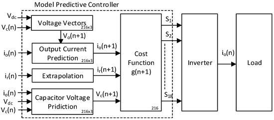
Figure 2.
Conventional MPCC for 4L-NNPC Converter.
The flow chart of the conventional MPCC technique for the 4L-NNPC converter is given in Figure 3a. First of all, the measured value of DC link voltage and load currents are needed at the nth instant. User-defined reference currents are taken for the purpose of ease. In the next step, 216 VVs are calculated using Equation (1) for all possible switching states on the inverter. After that, 216 output currents are predicted using Equation (8) for all possible VVs. Similarly, 216 predicted FC voltages are obtained using Equation (12).
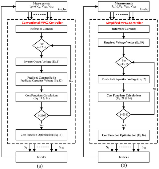
Figure 3.
Flow Chart for 4L-NNPC current control, (a) Conventional MPCC, (b) Simplified MPCC.
After that, two control goals are defined in major cost function , elimination of error in load current using the sub-cost function and regulation of FC voltages using the sub-cost function as follows [42]:
where is the reference voltages of the flying capacitor and is the weighting factor which is defined as follows [42]:
where io,n is the rated value of converter output current. The major cost function can be described in this fashion by bringing together the above two sub-cost functions and :
The fundamental theme of the optimization process is to obtain a cost function near zero. The predicted reference current is compared with 216 predicted load currents. And the reference FC voltage is compared with 216 predicted values of FC voltages. The switching state that belongs to the smallest value of the cost function is chosen for the subsequent interval.
Finally, the conventional MPCC of the 4L-NNPC converter can be summarized by the following mathematical expressions:
4. Simplified MPCC of the 4L-NNPC Converter
The block diagram of the simplified MPCC, as shown in Figure 4, is a modified form of the MPCC algorithm used to reduce the calculation burden on the digital microprocessor for real-time implementation. In this technique, only one required voltage vector (RVV) is predicted for the optimization process instead of 216 current predictions per phase. Consequently, the suggested RVV technique simplifies the control process.
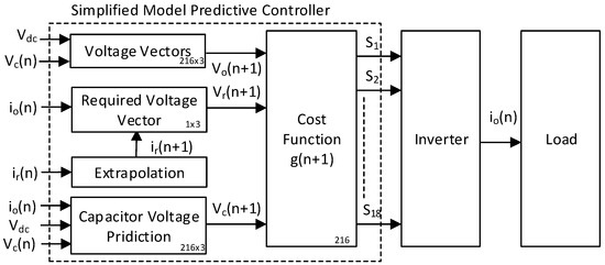
Figure 4.
Simplified MPCC for 4L-NNPC Converter.
The main theme of the conventional MPCC of the 4L-NNPC converter is to choose a suitable VV from 216 output VVs using Equation (8) for the next interval that corresponds to the nearly zero error between the predicted output current and the reference output current. For this purpose, all 216 VVs are analyzed for current prediction and the 216 predicted currents are compared in sub-cost function . After cost function optimization, a suitable voltage vector is selected for the next interval.
In the simplified MPCC technique, a required voltage vector (RVV) is obtained that corresponds to the exactly zero output current tracking error. After that, this RVV is compared with all VVs using the sub-cost function, and a suitable voltage vector is chosen for the next interval. In this method, 216 current predictions are eliminated because the suitable voltage vector is directly obtained using RVV.
The required voltage vector can be derived by replacing the predicted output current with the predicted reference in Equation (8), which shows that the predicted current is taken exactly equal to the reference current for zero current tracking error.
Rearranging the Equation (19).
According to Equation (19), the output current of the converter will be identical to its reference current if the output voltage of the converter is managed to be the same as RVV .
Implementation of the simplified MPCC technique is described using the flow chart given in Figure 3b. According to this flow chart, the first step of the simplified MPCC will be to measure the value of DC link voltages and load currents. The reference signal values for load currents are produced according to the application of the 4L-NNPC converter. Reference currents are user-defined for generality. So, the given technique can be implemented for further application by modifying the reference values.
The reference currents should be predicted to future state because the cost function performs the calculation in an (n + 1)th instant. In case of a very small sampling time, such as , there is no need for a reference currents prediction and is taken equal to the . When the sampling time is large, such as , the given fourth-order Lagrange extrapolation can be used for a reference currents prediction:
In the next step, 216 predicted output currents per phase are eliminated due to one proposed RVV per phase. The RVV can be achieved using Equation (19).
Two control goals are defined in cost function : the elimination of error in load current, and the regulation of FC voltages. The primary purpose is to diminish the error among predicted load current and reference current, which can be achieved using the sub-cost function as defined below:
According to the sub-cost function , 216 possible VVs are compared with the one proposed RVV. Consequently, 216 errors are generated from the cost function .
The secondary control goal is defined in the sub -cost function : to adjust the FC voltages at a constant level of one-third of DC link voltages. Sub-cost function is defined in Equation (14). The major cost function can be described in this fashion by bringing together the above two sub-cost functions and as given in Equation (16).
The fundamental theme of the optimization process is to obtain a cost function near zero. The RVV is compared with 216 predicted converter voltage vectors in each sampling interval. Similarly, the reference FC voltage is compared with 216 predicted values of FC voltages. The switching state that belongs to the smallest value of the cost function is chosen for the subsequent interval. Finally, the simplified MPCC of the 4L-NNPC converter can be summarized by the following mathematical expressions.
It can be observed that 216 calculations of current prediction for each phase are reduced to just one calculation for obtaining the RVV. Consequently, the calculation burden of the microprocessor is significantly reduced.
5. Simulation Results and Discussion
To investigate the simplified and conventional schemes for the 4L-NNPC converter, simulations are performed using MATLAB Simulink. The 4L-NNPC converter parameters and the MPCC parameters are listed in Table 2 and Table 3, respectively. The simulation results are analyzed for output voltages, load currents, and regulation of FC voltages. The robustness analysis of simplified and conventional techniques with DC link voltage variations are also discussed.
Table 2.
4L-NNPC converter parameter.
Table 3.
4L-NNPC converter parameter.
5.1. Steady-State Analysis
Figure 5 displays the simulation results of both techniques for the steady-state condition with balanced reference currents and balanced loads for , reference currents ( at 50 Hz, and balanced loads . It shows that output load currents follow their references with minimum error for both controllers. Output currents and reference currents are compared for percentage error. A very low percentage error of 0.35% is seen in the case of the simplified MPCC technique as compared to 0.86% for the conventional MPCC technique. In the case of steady-state current conditions, simulation time for 5000 samples is analyzed. Computational time is reduced to 1.85 s in the case of the simplified MPCC technique as compared to 2.3 s in that of the conventional MPCC technique. Consequently, calculation time is reduced by 19.56% in the case of a simplified MPCC algorithm as compared to the conventional algorithm. The average switching frequency is calculated at 1237 Hz in the case of the conventional MPCC technique and 1136 Hz in the case of the simplified MPCC technique, which indicates a 8.16% reduction in switching frequency. Total harmonic distortion (THD) in load current is analyzed in a steady-state condition. THD is reduced to 0.29% in the case of the simplified MPCC technique as compared to 0.36% in that of the conventional MPCC technique. The comparison of the proposed and the conventional MPCC technique is given in Table 4 for better understanding. The results shows that the proposed simplified MPCC technique is better than the conventional MPCC technique in all respects.
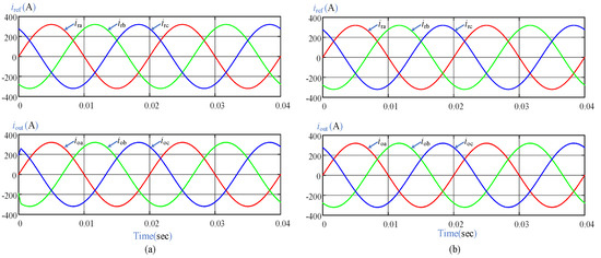
Figure 5.
Reference and output currents for steady-state condition; (a) Conventional MPCC, (b) Simplified MPCC.
Table 4.
Comparison of conventional and simplified MPCC techniques for steady-state reference currents.
Figure 6 displays the FC voltages in the case of steady-state references of load currents. It can be observed from the simulation result that FCs voltages are regulated at the level of of for both controllers. Output phase voltages Vao, phase to phase voltages Vab, and phase to neutral point voltages Van are shown in Figure 7 in steady-state conditions.
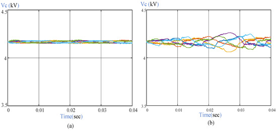
Figure 6.
FC voltages for steady-state condition; (a) Conventional MPCC, (b) Simplified MPCC.
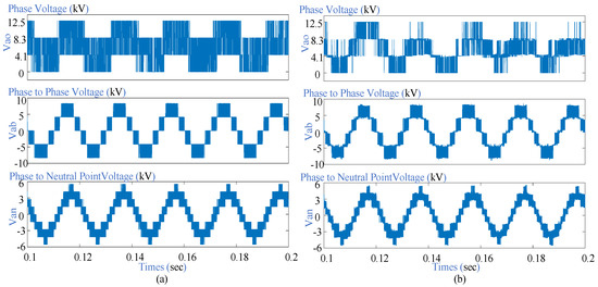
Figure 7.
Output voltages of the 4L-NNPC converter; (a) Conventional MPCC, (b) Simplified MPCC.
5.2. Transient-State Analysis
5.2.1. Balance Reference Step Change
The transient-state analysis is carried out using step change in the reference current from to at 50 Hz with balanced loads ) and sampling time . The step change in signal is applied during the interval of to . Simulation results of load currents and FC voltages are shown in Figure 8 for both controllers. It can be observed that output load currents follow their references well during step change and FCs voltages are also regulated to an acceptable range during transitions. Further analysis is described in Section 5.4.
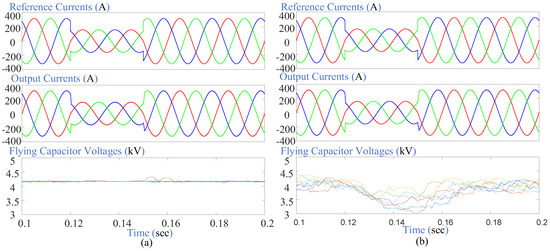
Figure 8.
Transient analysis; a step change in reference current; (a) Conventional MPCC, (b) Simplified MPCC.
5.2.2. Balanced Reference Falling Ramp Change
The transient-state analysis is also carried out using falling ramp change in the reference current from to at 50 Hz with balanced loads ) and sampling time . Falling ramp change in reference signals is applied during the interval of to . The simulation result of load currents and FCs voltages during the transition state is given in Figure 9. It shows that output load currents keep tracking their references at an acceptable level, while falling ramp change and FCs voltages are also regulated to an acceptable range during the transition period for both controllers. Further analysis is described in Section 5.4.
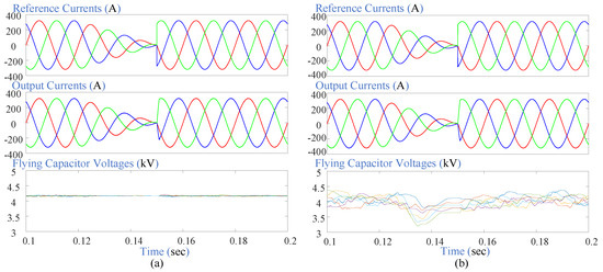
Figure 9.
Transient analysis; ramp change in reference current; (a) Conventional MPCC, (b) Simplified MPCC.
5.3. Robustness Analysis with DC Link Voltage Variations
The robustness of the MPCC technique is analyzed with ramp and step variation in DC bus voltage.
5.3.1. Ramp Change in DC Link Voltage
Ramp alteration in DC link voltage is analyzed for the following parameters: DC link falling ramp change from 12.5 kV to 11 kV, balanced reference currents at 50 Hz), balanced loads (), and sampling time . Falling ramp change in DC link voltages is applied during the interval of to . Simulation results of load currents, DC link voltages, and FCs voltages during the transition state are is given in Figure 10 for both controllers. It can be seen that load current keeps tracking its references at an acceptable level while falling ramp change in DC link voltages and FCs voltages are also regulated to an acceptable range during the transition period. Further analysis is described in Section 5.4.
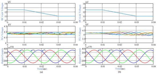
Figure 10.
Robustness analysis; ramp change in DC link voltage; (a) Conventional MPCC, (b) Simplified MPCC.
5.3.2. Step Change in DC Link Voltage
Step alteration in DC link voltage is analyzed using these parameters: DC link step changes 12.5 KV to 11 KV from time to , 11 kV to 12 kV from time to and 12.5 KV from , balanced reference currents at 50 Hz, balanced loads (), and sampling time . Simulation results of load currents, DC link voltages, and FCs voltages during the transition state are given in Figure 11 for both controllers. It can be seen that load current keeps tracking its references at an acceptable level while step change in DC Link voltages and FCs voltages are also regulated to an acceptable range during the transition period.
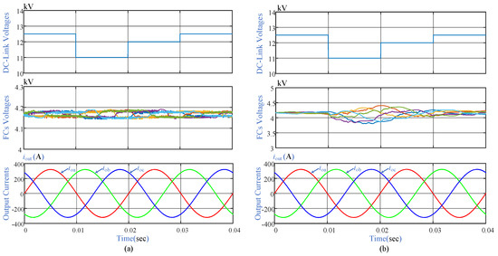
Figure 11.
Robustness analysis; step change in DC link voltage; (a) Conventional MPCC, (b) Simplified MPCC.
5.4. Comparative Analysis
To verify the effectiveness of the proposed MPCC technique, a comparative analysis for different conditions of the reference current and DC link voltages has been done. In the bar chart, different operating conditions mentioned in Table 5 are given along the x-axis as follows: A represents steady-state reference current, B represents reference current step change, C represents reference current falling ramp, D represents reference current rising ramp, E represents DC link voltage step change, F represents DC link voltage falling ramp, and G represents DC link voltage rising ramp. All of the comparative analyses are carried out for 5000 sampling instants.
Table 5.
Operating conditions for 4L-NNPC converter.
Figure 12 shows the computational time comparison between the conventional and simplified MPCC for all operating conditions. MATLAB function is used to measure the computational time of both controllers. The bar chart shows that computational time is reduced in the simplified MPCC technique as compared to the conventional MPCC in all operating conditions. Computational time is reduced to a maximum of 20% in case C (reference current falling ramp change) and a minimum of 17.3% in case E (DC link voltage step change).
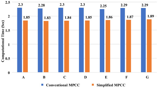
Figure 12.
Comparison of computational time for different conditions.
Figure 13 represents a comparative analysis of the conventional and simplified MPCC with respect to the percentage error between the reference current and the output current. The bar chart demonstrates that percentage errors are reduced in the simplified MPCC technique as compared to the conventional MPCC in all operating conditions, which proves the effectiveness of the proposed technique. The percentage error of the current is reduced the most in case A (steady-state reference current), from 0.86% to 0.35%, which shows the 59.3% decrease with respect to the conventional MPCC percentage error. On the other hand, the percentage error of the current is reduced the least in case C (reference current ramp change), from 0.91% to 0.55%, which shows the 39.5% decrease with respect to the conventional MPCC percentage error.
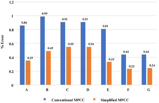
Figure 13.
Comparison of current % error for different conditions.
Comparative analysis of the average switching frequency for the conventional and simplified MPCC is expressed in Figure 14. All operating conditions, as mentioned in Table 5, are compared for both the conventional and simplified MPCC techniques. The results show that the average switching frequency is reduced in all operating conditions for the simplified MPCC technique. The average switching frequency is reduced the most in case F (DC link ramp change), from 1130 to 880 Hz, which shows a 22.1% decrease with respect to the conventional MPCC technique. On the other hand, the average switching frequency of the simplified MPCC is reduced the least in case B (reference current step change), from 1131 to 1132 Hz, which shows the 8.04% decrease with respect to the conventional MPCC technique.
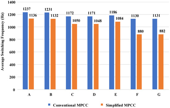
Figure 14.
Comparison of average switching frequency for different conditions.
6. Conclusions
An improved and simplified MPCC technique is applied to the 4L-NNPC converter to diminish the calculation burden of the microprocessor caused by the heavy calculations of the conventional MPCC. In this proposed technique, 216 current predictions of the conventional method are converted into one required voltage vector (RVV) prediction for each phase. Consequently, the computational time of the proposed MPCC is reduced due to the reduction of calculations from 216 × 3 to 1 × 3. The results show the computational time of the conventional MPCC is reduced by 19.56% using the proposed MPCC, while keeping a good tracking of output current with respect to the reference current. The switching frequency and THD of the proposed method are reduced by 8.16% and 0.07%, respectively, as compared to the conventional MPCC technique. These results demonstrate that the performance of the simplified MPCC is improved as compared to the conventional MPCC. These results verify that the simplified MPCC algorithm can be employed with low-price processors. Furthermore, the proposed simplified technique is also valid for other converters.
Author Contributions
Conceptualization, R.A.; data curation, M.H.; formal analysis, H.M.M.; funding acquisition, M.A. and S.I.; investigation, M.A. and M.S.; methodology, M.S.R.S.; project administration, H.M.M. and M.A.; supervision, M.H.; validation, M.B.S.; writing—original draft, R.A.; writing—review & editing, H.M.M. All authors have read and agreed to the published version of the manuscript.
Funding
This research received no external funding.
Institutional Review Board Statement
Not applicable.
Informed Consent Statement
Not applicable.
Data Availability Statement
Not applicable.
Acknowledgments
This work was supported by the Researchers Supporting Project number (RSP2023R467), King Saud University, Riyadh, Saudi Arabia.
Conflicts of Interest
The authors declare no conflict of interest.
References
- Kouro, S.; Malinowski, M.; Gopakumar, K.; Pou, J.; Franquelo, L.G.; Wu, B.; Rodriguez, J.; Pérez, M.A.; Leon, J.I. Recent advances and industrial applications of multilevel converters. IEEE Trans. Ind. Electron. 2010, 57, 2553–2580. [Google Scholar] [CrossRef]
- Wang, K.; Zheng, Z.; Xu, L.; Li, Y. A four-level hybrid-clamped converter with natural capacitor voltage balancing ability. IEEE Trans. Power Electron. 2014, 29, 1152–1162. [Google Scholar] [CrossRef]
- Wu, B.; Narimani, M. High-Power Converters and AC Drives; John Wiley & Sons: Hoboken, NJ, USA, 2017; Volume 59. [Google Scholar]
- Rodriguez, J.; Lai, J.-S.; Peng, F.Z. Multilevel inverters: A survey of topologies, controls, and applications. IEEE Trans. Ind. Electron. 2002, 49, 724–738. [Google Scholar] [CrossRef]
- Rodríguez, J.; Bernet, S.; Wu, B.; Pontt, J.O.; Kouro, S. Multilevel voltage-source-converter topologies for industrial medium-voltage drives. IEEE Trans. Ind. Electron. 2007, 54, 2930–2945. [Google Scholar] [CrossRef]
- Saeedifard, M.; Barbosa, P.M.; Steimer, P.K. Operation and control of a hybrid seven-level converter. IEEE Trans. Power Electron. 2012, 27, 652–660. [Google Scholar] [CrossRef]
- Cortés, P.; Kazmierkowski, M.P.; Kennel, R.M.; Quevedo, D.E.; Rodríguez, J. Predictive control in power electronics and drives. IEEE Trans. Ind. Electron. 2008, 55, 4312–4324. [Google Scholar] [CrossRef]
- Cavalcanti, M.C.; De Oliveira, K.C.; De Farias, A.M.; Neves, F.A.; Azevedo, G.M.; Camboim, F.C. Modulation techniques to eliminate leakage currents in transformerless three-phase photovoltaic systems. IEEE Trans. Ind. Electron. 2010, 57, 1360–1368. [Google Scholar] [CrossRef]
- Buticchi, G.; Barater, D.; Lorenzani, E.; Franceschini, G. Digital control of actual grid-connected converters for ground leakage current reduction in PV transformerless systems. IEEE Trans. Ind. Inform. 2012, 8, 563–572. [Google Scholar] [CrossRef]
- Hou, C.-C.; Shih, C.-C.; Cheng, P.-T.; Hava, A.M. Common-mode voltage reduction pulsewidth modulation techniques for three-phase grid-connected converters. IEEE Trans. Power Electron. 2013, 28, 1971–1979. [Google Scholar] [CrossRef]
- Bradaschia, F.; Cavalcanti, M.C.; Ferraz, P.E.; Neves, F.A.; Santos, E.C.; da Silva, J.H. Modulation for three-phase transformerless Z-source inverter to reduce leakage currents in photovoltaic systems. IEEE Trans. Ind. Electron. 2011, 58, 5385–5395. [Google Scholar] [CrossRef]
- Kaźmierkowski, M.P.; Krishnan, R.; Blaabjerg, F. Control in Power Electronics: Selected Problems; Academic Press: Cambridge, MA, USA, 2002. [Google Scholar]
- Mohan, T.M.U.N.; Robbins, W.P. Power Electronics; Wiley: Hoboken, NJ, USA, 1995; Volume 2. [Google Scholar]
- Linder, A. Modellbasierte Prädiktivregelung in Der Antriebstechnik; Wuppertal University: Wuppertal, Germany, 2005. [Google Scholar]
- Rivera, M.; Rodriguez, J.; Espinoza, J.R.; Abu-Rub, H. Instantaneous reactive power minimization and current control for an indirect matrix converter under a distorted ac supply. IEEE Trans. Ind. Inform. 2012, 8, 482–490. [Google Scholar] [CrossRef]
- Anees, M.; Tariq, M.; Lodi, K.A.; Alam, M.; Chakrabortty, R.K.; Ryan, M.J. Reactive power compensation for grid by Packed-U-Cell inverter using model predictive control strategy with intelligent multi-objective scheme. J. Intell. Fuzzy Syst. 2022, 42, 793–806. [Google Scholar] [CrossRef]
- Alam, M.; Tariq, M.; Anees, M.A.; Azeem, A.; Lodi, K.A.; Bharatiraja, C. Model Predictive Control Based Reactive Power Compensation for Integration of Packed U Cell Inverter with Grid. In Proceedings of the 2018 IEEE International Conference on Power Electronics, Drives and Energy Systems (PEDES), 18–21 December 2018, Madras, India; IEEE: New York, NY, USA; pp. 1–6.
- Sanchez, P.M.; Machado, O.; Peña, E.J.B.; Rodríguez, F.J.; Meca, F.J. FPGA-based implementation of a predictive current controller for power converters. IEEE Trans. Ind. Inform. 2013, 9, 1312–1321. [Google Scholar] [CrossRef]
- Scoltock, J.; Geyer, T.; Madawala, U.K. A comparison of model predictive control schemes for MV induction motor drives. IEEE Trans. Ind. Inform. 2013, 9, 909–919. [Google Scholar] [CrossRef]
- Preindl, M.; Bolognani, S. Model predictive direct torque control with finite control set for PMSM drive systems, Part 1: Maximum torque per ampere operation. IEEE Trans. Ind. Inform. 2013, 9, 1912–1921. [Google Scholar] [CrossRef]
- Preindl, M.; Bolognani, S. Model predictive direct torque control with finite control set for PMSM drive systems, part 2: Field weakening operation. IEEE Trans. Ind. Inform. 2013, 9, 648–657. [Google Scholar] [CrossRef]
- Xia, C.; Wang, M.; Song, Z.; Liu, T. Robust model predictive current control of three-phase voltage source PWM rectifier with online disturbance observation. IEEE Trans. Ind. Inform. 2012, 8, 459–471. [Google Scholar] [CrossRef]
- Stephens, M.A.; Manzie, C.; Good, M.C. Model predictive control for reference tracking on an industrial machine tool servo drive. IEEE Trans. Ind. Inform. 2013, 9, 808–816. [Google Scholar] [CrossRef]
- Kennel, F.; Gorges, D.; Liu, S. Energy management for smart grids with electric vehicles based on hierarchical MPC. IEEE Trans. Ind. Inform. 2013, 9, 1528–1537. [Google Scholar] [CrossRef]
- Vyncke, T.J.; Thielemans, S.; Melkebeek, J.A. Finite-set model-based predictive control for flying-capacitor converters: Cost function design and efficient FPGA implementation. IEEE Trans. Ind. Inform. 2013, 9, 1113–1121. [Google Scholar] [CrossRef]
- Toit, D.D.; Mouton, H.T.; Kennel, R.; Stolze, P. Predictive control of series stacked flying-capacitor active rectifiers. IEEE Trans. Ind. Inform. 2013, 9, 697–707. [Google Scholar] [CrossRef]
- Acuna, P.; Moran, L.; Rivera, M.; Dixon, J.; Rodriguez, J. Improved active power filter performance for renewable power generation systems. IEEE Trans. Power Electron. 2014, 29, 687–694. [Google Scholar] [CrossRef]
- Yan, Z.; Wang, J. Model predictive control of nonlinear systems with unmodeled dynamics based on feedforward and recurrent neural networks. IEEE Trans. Ind. Inform. 2012, 8, 746–756. [Google Scholar] [CrossRef]
- Yaramasu, V.; Rivera, M.; Wu, B.; Rodriguez, J. Model predictive current control of two-level four-leg inverters—Part I: Concept, algorithm, and simulation analysis. IEEE Trans. Power Electron. 2013, 28, 3459–3468. [Google Scholar] [CrossRef]
- Rivera, M.; Wilson, A.; Rojas, C.A.; Rodriguez, J.; Espinoza, J.R.; Wheeler, P.W.; Empringham, L. A comparative assessment of model predictive current control and space vector modulation in a direct matrix converter. IEEE Trans. Ind. Electron. 2013, 60, 578–588. [Google Scholar] [CrossRef]
- Rodriguez, J.; Kazmierkowski, M.P.; Espinoza, J.R.; Zanchetta, P.; Abu-Rub, H.; Young, H.A.; Rojas, C.A. State of the art of finite control set model predictive control in power electronics. IEEE Trans. Ind. Inform. 2013, 9, 1003–1016. [Google Scholar] [CrossRef]
- Alam, M.; Ahmad, S.; Anees, M.A.; Tariq, M.; Azeem, A. Comprehensive Review on Model Predictive Control Applied to Power Electronics. Recent Adv. Electr. Electron. Eng. Former. Recent Pat. Electr. Electron. Eng. 2020, 13, 632–640. [Google Scholar] [CrossRef]
- Cortés, P.; Ortiz, G.; Yuz, J.I.; Rodríguez, J.; Vazquez, S.; Franquelo, L.G. Model predictive control of an inverter with output $ LC $ filter for UPS applications. IEEE Trans. Ind. Electron. 2009, 56, 1875–1883. [Google Scholar] [CrossRef]
- Iqbal, H.; Tariq, M.; Sarfraz, M.; Anees, M.A.; Alhosaini, W.; Sarwar, A. Model predictive control of Packed U-Cell inverter for microgrid applications. Energy Rep. 2022, 8, 813–830. [Google Scholar] [CrossRef]
- Hassan, M.; Atif, R.; Ge, X.; Teklu, W.A.; Munir, H.M.; Amjad, M. Model predictive current control of multilevel inverter in traction system. In Proceedings of the 2019 International Conference on Electrical, Communication, and Computer Engineering (ICECCE), Swat, Pakistan, 24–25 July 2019. [Google Scholar]
- Rodriguez, J.; Pontt, J.; Silva, C.A.; Correa, P.; Lezana, P.; Cortés, P.; Ammann, U. Predictive current control of a voltage source inverter. IEEE Trans. Ind. Electron. 2007, 54, 495–503. [Google Scholar] [CrossRef]
- Cortes, P.; Rodriguez, J.; Silva, C.; Flores, A. Delay compensation in model predictive current control of a three-phase inverter. IEEE Trans. Ind. Electron. 2012, 59, 1323–1325. [Google Scholar] [CrossRef]
- Xia, C.; Liu, T.; Shi, T.; Song, Z. A simplified finite-control-set model-predictive control for power converters. IEEE Trans. Ind. Inform. 2013, 10, 991–1002. [Google Scholar]
- Bilal Waheed, M.; Bhatti, A.R.; Amjad, M.; Saleem, Y.; Niazi, S.A.; Khokhar, S. A simplified model predictive control of four-leg two-level inverter. Electr. Power Compon. Syst. 2019, 47, 1287–1302. [Google Scholar] [CrossRef]
- Hassan, M.; Ge, X.; Atif, R.; Woldegiorgis, A.T.; Mastoi, M.S.; Shahid, M.B. Computational efficient model predictive current control for interior permanent magnet synchronous motor drives. IET Power Electron. 2022, 15, 1111–1133. [Google Scholar] [CrossRef]
- Narimani, M.; Wu, B.; Cheng, Z.; Zargari, N.R. A new nested neutral point-clamped (NNPC) converter for medium-voltage (MV) power conversion. IEEE Trans. Power Electron. 2014, 29, 6375–6382. [Google Scholar] [CrossRef]
- Narimani, M.; Wu, B.; Yaramasu, V.; Cheng, Z.; Zargari, N.R. Finite control-set model predictive control (FCS-MPC) of nested neutral point-clamped (NNPC) converter. IEEE Trans. Power Electron. 2015, 30, 7262–7269. [Google Scholar] [CrossRef]


Disclaimer/Publisher’s Note: The statements, opinions and data contained in all publications are solely those of the individual author(s) and contributor(s) and not of MDPI and/or the editor(s). MDPI and/or the editor(s) disclaim responsibility for any injury to people or property resulting from any ideas, methods, instructions or products referred to in the content. |
© 2023 by the authors. Licensee MDPI, Basel, Switzerland. This article is an open access article distributed under the terms and conditions of the Creative Commons Attribution (CC BY) license (https://creativecommons.org/licenses/by/4.0/).