1. Introduction
Heat transfer augmentation techniques are essential in many industrial applications because they allow for compact heat exchangers with high thermal performance [
1].
Several studies have shown interest in improving heat transfer in engineering applications. There are typically three methods for improving heat transfer: Active, passive, and compound techniques. In the active technique, an external source of energy is required to enhance the heat transfer such as surface vibration, magnetic field, jet impingement, etc. In the passive technique, the configuration of the system has some modifications to improve the heat transfer such as ribs and dimples, rough surfaces, nanoparticles, etc. In the compound technique, the combination of active and passive methods occurs [
2].
The passive technique can be divided into three groups (using nanoparticles, geometry modifications, and a combination between nanoparticles and geometry modifications) as follows:
Firstly, nanoparticles are added to the fluid to create nanofluids. Nanofluids have recently been seen as a promising choice for thermal fluids and can be effectively used for heat transfer. The nanofluids significantly enhance the heat exchanger’s thermal performance in various applications, such as CPU (central processing unit) coolers [
3] and annulus and plate heat exchangers [
4]. On the other hand, the nanoparticles were also added to phase-change materials (PCMs) to enhance their thermal conductivity in different applications [
5,
6].
Secondly, geometry modifications are made by using dimples [
7] or roughening the heat transfer surfaces using grooves, ribs or wires, or helically corrugated tubes [
8,
9,
10]. Artificial roughness is used in several applications such as evaporators, steam condensers, blades of gas turbines, cooling channels, heat exchangers, and solar air heaters [
11,
12].
Due to the secondary flow areas that form near the wall and decrease the thickness of the thermal boundary layer in a way that increases the rate of heat transfer, these modified geometries produce good mixing in the fluid flow.
Unfortunately, adopting these methods to speed up the heat transfer rate sometimes results in an increase in the pressure drop as a side effect [
8,
9]. The impact of the channel rib and flow features on heat transfer and friction factor characteristics has been demonstrated by several experimental and numerical studies [
13,
14].
Moon et al. [
15] numerically investigated the configuration of 16 ribs with various cross-sectional shapes and found that boot-shaped rib turbulators have the maximum heat transfer performance with a similar pressure penalty to that of the square rib. In addition, the size of the recirculating zone is directly impacted by the slope of the front surface of the rib, making it a crucial component in determining the performance of heat transfer.
Pingan et al. [
11] numerically studied the heat transfer of the airflow in a channel with various rib shapes (triangular, semi-circular, and rectangular) using a standard k-ε turbulent model with enhanced wall treatment. It was found that the maximum and minimum values of the average Nusselt number of the channel occurred with the triangular and rectangular ribs, respectively.
Finally, several researchers concentrated on utilizing both previous methods of enhancing heat transfer (using ribs and nanoparticles). For instance, Wongcharee and Eiamsa-ard [
16] conducted an experimental study on the flow of a turbulent CuO-water nanofluid inside a corrugated tube. It was observed that the heat transfer for this geometry increases by 1.57 times compared to the pure fluid inside the simple tube when a 0.7% volume fraction of CuO is used.
Manca et al. [
17] numerically investigated the turbulent forced convection of an Al
2O
3-water nanofluid in a ribbed channel with different rib shapes (square and rectangular). It was observed that although there is a greater pressure drop penalty, the enhancement of heat transfer grows with the volume fraction of the particles and Reynolds number. The pressure drop and heat transfer rate are improved by using the ribbed surfaces and adding nanoparticles to the base fluid.
Overall, the spanwise vortices created by the ribs break up the boundary layer and cause flow separation and reattachment in the inter-rib area, which causes turbulence. A higher rate of convective heat transfer results from the high magnitude of turbulent transport because it improves heat exchange through good mixing. However, the rib turbulators also increase the pressure drop and the consumption of energy, which has an impact on the thermal system’s total thermo-hydraulic performance [
18]. Therefore, finding the optimum rib design is crucial in order to maximize heat transfer while minimizing pressure drop.
As previously mentioned, the flow behavior in ribbed channels was studied to produce a significant enhancement in heat transfer rates. The flow recirculation patterns around a single rib are described by Cho et al. [
19]. A large recirculation zone is created at the lee-side regions downstream of the rib, accompanied by a small vortex in the vicinity of the bottom corner of the rib. These recirculation zones encompass a sizable portion of the rib and bottom wall, which is frequently regarded as having poor heat transfer and locally low surface Nusselt numbers [
20].
Consequently, the optimum design is the case that increases the performance of heat transfer with a small value of pressure drop. Therefore, to obtain the best design conditions, a trade-off between the increase in heat transfer and the decrease in the pressure drop should be performed.
It can be observed from the previous literature review that most of the studies focused separately on the effect of the rib shape, spacing, and height in a duct or a tube with one fluid. The optimum rib shape in a counter flat plate heat exchanger (hot and cold flow) for a complete heat transfer process between two turbulent fluids has not been studied before.
This research gap is the aim of this paper, and the present design can be used in waste heat recovery systems. In the present paper, the influence of the different rib shapes (rectangular and triangular) with different heights (H: 2.5, 5, 7.5, and 10 mm) and spacing (S: 75, 95, 128, and 195 mm) is investigated on the performance of the heat transfer and pressure drop. The thermal-hydraulic parameter, which combines an enhancement of the rate of heat transfer and the pressure drop due to friction, is also studied on hot and cold sides to obtain the best design of the flat plate heat exchanger.
2. Theoretical Modeling
The current work studied the different types of rib shapes, heights, and spaces to optimize the design that can improve the thermal performance of the heat exchanger. The flat plate heat exchanger consisted of five channels: Three channels for the hot air flow (at Re = 3210 and T = 260 °C) and two channels for the cold air flow (at Re = 9880 and T = 27 °C). The previous conditions were selected to match the velocity of the hot fluid (exhaust gases) and cold fluid (intake air) in waste heat recovery systems, especially for a cold start-up in diesel engines as in Ref [
6,
21]. The length and width of the heat exchanger were 400 mm and 180 mm, respectively, with a 30 mm height for the hot and cold channels. A counterflow was created between the hot and cold air, which can increase the heat transfer between them. The cold air passes through two channels (L × W × H: 400 × 180 × 30 mm) and the hot air passes through three channels of the same dimensions. The separation wall between the hot and cold channels was made of aluminum with a 4 mm thickness. Two types of ribs (rectangular and triangular shapes) were studied to compare the results and obtain the optimum design.
Different numbers of ribs with increasing spacings (S: 75, 95, 128, and 195 mm) and heights (H: 2.5, 5, 7.5, and 10 mm) in two shapes (rectangular and triangular) were simulated in cases A, B, C, and D. The rectangular ribs were represented in case A, and the triangular ribs with sloping in the direction of the cold airflow and the hot airflow were represented in cases B and C, respectively. The previously mentioned cases with case D (no ribs) are displayed in
Figure 1, and the geometry of the triangular and rectangular ribbed flat plate heat exchangers is presented in
Figure 2.
The turbulent renormalization group model (RNG k-ε model) displays the flow regime of the turbulent flow of the cold and hot air. The governing equations that rule the heat transfer and the motion of a fluid are the continuity, momentum, and energy equations, which can be described as follows [
6,
21]:
Momentum:
where
Sij is the main strain rate and is estimated by the following equation:
represents the unknown turbulent or Reynolds-stress tensor and signifies the velocity fluctuation in the i-direction.
Energy:
where
E indicates the total energy, (
τij) eff denotes the stress tensor,
k represents the thermal conductivity (W/m °C), and Pr
t is a turbulent Prandtl number.
The description of turbulence using two transport partial differential equations is given by the k-ε model (PDEs). It can be divided into three types, standard, renormalization group (RNG), and realizable k-ε models. The theory of the renormalization group is a statistical technique that is used to develop the RNG model. The transport equation of k (turbulence kinetic energy) and ε (turbulence dissipation rate) for steady flow can be defined as follows [
22]:
and
where:
µeff denotes the effective viscosity at the high values of Reynolds numbers.
αk and αε indicate the inverse effective Prandtl numbers (αk = αε = 1.393).
Gk is the generation of turbulence kinetic energy due to the mean velocity gradients.
Gb is the generation of turbulence kinetic energy due to buoyancy.
YM is the effect of the fluctuating dilatation incompressible turbulence on the overall dissipation rate.
S
k and S
ε are user-defined source terms.
The present model is established by the following model constants: Cµ = 0.0845, C1ε = 1.44, and C2ε = 1.92.
The enhancement of the heat transfer rate can be calculated in terms of the thermal-hydraulic parameter (η), which is described by the following equation [
23]:
where
f and
fs represent the friction coefficients for the ribbed channel and the smooth channel, respectively. In addition,
Nu and
Nus are the Nusselt numbers for the ribbed channel and the smooth channel, respectively.
The thermal-hydraulic parameter combines the enhancement of the rate of heat transfer and the pressure drop due to friction to obtain the best design of the flat plate heat exchanger.
3. Numerical Simulation
Numerical simulations were carried out to analyze the process of heat transfer using commercial code ANSYS 2022 R2, thereby employing a finite volume approach to discretize the governing equations.
3.1. Boundary and Initial Conditions
The entire device was initially at an ambient temperature of 27 °C. For the inlet of both the hot and cold airflow, a uniform velocity distribution with uniform temperature was created. The boundary conditions for the inlets of the duct were estimated to be a velocity inlet. At the same time, the pressure outlets were selected for the duct’s exits and the outer walls of the heat exchangers were insulated.
3.2. Solution Procedures
The turbulence model for hot and cold airflows was considered along with initial and boundary conditions. The numerical simulation of the model was developed using ANSYS 2022 R2 software. The pressure–velocity coupling equations were determined using the semi-implicit method for the pressure-linked equations (SIMPLE) scheme. The governing equations in conjunction with the boundary and initial conditions were described using a control volume approach. The central difference and QUICK schemes were used to describe the diffusion and convection terms, respectively. For velocity–pressure coupling, the SIMPLER algorithm was applied. Iterative calculations were nonstop until all problem variables satisfied a relative convergence criterion of 10−6.
3.3. Model Validation
The present model was numerically solved, and the predicted results were compared with the experimentally published results of the turbulence model. Under the same operating conditions, the numerical results were validated.
The turbulent flow through the hot and cold air channels was fabricated, and the numerical model recognized in this work was validated against the numerical study by Menge et al. [
24].
Figure 3 illustrates the boundary conditions of the published model [
24] as follows: The inlet boundary is defined as a velocity inlet with a uniform velocity of 1 m/s. In addition, at the inlet, the relative turbulent intensity is equal to 5%. The outlet boundary is defined as a pressure outlet with an average static reference pressure of 0 Pa. The Solver was double precision, pressure based, and implicit. The pressure–velocity coupling was SIMPLE, and the turbulent kinetic energy and the turbulent dissipation rate were second-ordered upwind with a convergence criterion of 1 × 10
−6.
Figure 4 indicates the relationship between the axial velocity and the pipe inlet position to the point at which the entire pipe reaches a constant value using the present numerical model and the published model. As seen in the figure, they match each other well.
3.4. Mesh Generation and Mesh Independence Test
ANSYS-Design Modeler 2022 R2 software was used to create the fluid domain for a fully developed channel with a certain height (
h). The dimensions were chosen to confirm a fully developed flow and to facilitate a comparison with Blasius. The fluid region was discretized by using the finite element method through the ANSYS-Mesh 2022 R2. Two different techniques are used to distribute the cell through the cold and hot channels. Firstly, through the channel length in the x-direction, the cells were uniformly distributed. Secondly, through the channel height in the y-direction, the cells were non-uniformly distributed. The grid was recognized so that it could capture the velocity distribution in all near-wall regions of the flow. ANSYS-Mesh 2022 R2 software was used to generate the mesh independence test with a non-uniform range of cells. The cell number started with 20 to 50 cells, which were distributed through the height of the channel with a growth rate (GR) equal to 1.1. The RNG k-ε model was employed with enhanced wall treatment, which can be simulated in the near-wall region. Using this option, the height of the first cell near the wall, which is called y
+, is acceptable when y
+ ˂ 4 [
22]. A numerical study was established to study the two-dimensional (2-D) flow and heat transfer in the ribbed duct at two values of Reynolds numbers when using rectangular and triangular ribs.
In FLUENT, the finite volume technique was used to solve the continuity, momentum, and energy equations that define heat transfer and fluid flow under given boundary conditions. The continuity and momentum equation residuals have been estimated to be 10−4 and 10−6 for the energy equation.
Figure 5 compares the skin coefficient values (𝐶
𝑓) at different cell numbers per height for both hot and cold channels, and the skin coefficient drops with the increase in the cell number. The relationship between the skin coefficients of both hot and cold channels at different values of the first cell height 𝑦
+ (𝑦
+ = 𝑢
𝜏𝑦/𝜈) is shown in
Figure 6, and the skin coefficient declines when reducing the first cell height.
It is observed from the figures that, for both hot and cold air flows, the skin coefficient value shows a slight change when the number of cells per height increases above 45 cells. Thus, the optimal cell number per channel height with a small error in the results is 45 cells at a growth rate of 1.1 and y+ of 0.26.
4. Results and Discussion
The obtained results elucidate the effect of rectangular and triangular ribs on the thermal performance of the flat plate heat exchanger and compare them to obtain the optimum design.
4.1. Flow Structure in Ribbed Duct
The main concept of designing ribbed ducts is to achieve higher flow turbulence and hence greater heat transfer. The predicted velocity contours for the rectangular and triangular ribs are shown in
Table 1. It can be observed that both hot and cold airflow accelerates and decelerates through the passage due to the contraction and expansion caused by the ribs.
In the triangular ribs, the fluid motion of a highly turbulent Reynolds number in the cold airflow has a wavy style due to the slope of the ribs. In addition, the recirculation regions developed by the ribs are increased with the increase in the Reynolds number as mentioned in Ref [
25]. However, through the rectangular ribs, the fluid motion through the high- and low-turbulence Reynolds numbers is stable. The flow separates and then reattaches as mentioned in Refs [
26,
27]; therefore, there is non-complete contact with the wall at some points on the cold air side (high Reynolds number), but on the hot air side (low Reynolds number), it is uniform in the triangular ribs.
In the rectangular ribs, when the flow is on the upper side, a large recirculation zone is created at the lee-side regions on the lower side of the rib. Moreover, when the flow is on the lower side, a large recirculation zone is created at the lee-side regions on the upper side of the rib. For both of the previous positions, there is a small vortex in the vicinity of the bottom corner of the rib. This description of the flow is in agreement with that mentioned in Ref [
19]. These recirculation zones encompass a sizable portion of the rib and bottom wall, which is frequently regarded as having poor heat transfer and locally low surface Nusselt numbers [
20]. On the other hand, the low Reynolds number in the hot airflow has no wavy motion through the velocity contours.
Table 2 shows the contours of the turbulence intensity for all cases of the RNG turbulence model. It can be realized from these contours that the turbulence intensity is higher downstream of the upper edge of the ribs where the major shear layer region is located due to the non-uniform velocity and motion of the fluid through the triangular ribs as mentioned before due to the separation and reattaching of the fluids. This motion makes non-complete contact with the wall at some points on the cold air side (high Reynolds number) but the hot air side (low Reynolds number) is uniform. The turbulence intensity is also non-uniform, especially in the highly turbulent Reynolds number as in the cold airflow.
As shown in the contours, the weak and robust intensity is established according to the cold air position after the ribs. The cold-air-side turbulence intensity in rectangular ribs is higher than in triangular ribs due to the aforementioned intensity fluctuations. However, on the hot air side, the slope of the triangular ribs causes the intensity after the ribs to be more concentrated than the rectangular ones.
The predicted contours of the temperature distribution for the ribbed cross-sectional passages are shown in
Table 3. It was found that the temperature of both fluids near the wall was most affected by the ribs. Due to the effect on the circulation generated by the ribs, the heat transfer between the cold and hot fluid flows is increased.
4.2. The Ribs’ Height Effect
Figure 7 illustrates the variation of the convection heat transfer coefficient for the hot and cold channels with different heights, spacings, and shapes of ribs. The figure also demonstrates that the convection heat transfer coefficient increases with the increase in the rib height, and the maximum value occurs at a spacing of 75 mm for the rectangular and triangular ribs. The convection heat transfer coefficient in the triangular ribs is higher than in the rectangular ones, especially for the hot air side.
For both rectangular and triangular ribs, the convection heat transfer coefficient gradually increases until the rib height reaches 7.5 mm. At this rib height, there is a significant increase in the convection coefficient due to the higher flow turbulence as mentioned in
Table 1,
Table 2 and
Table 3.
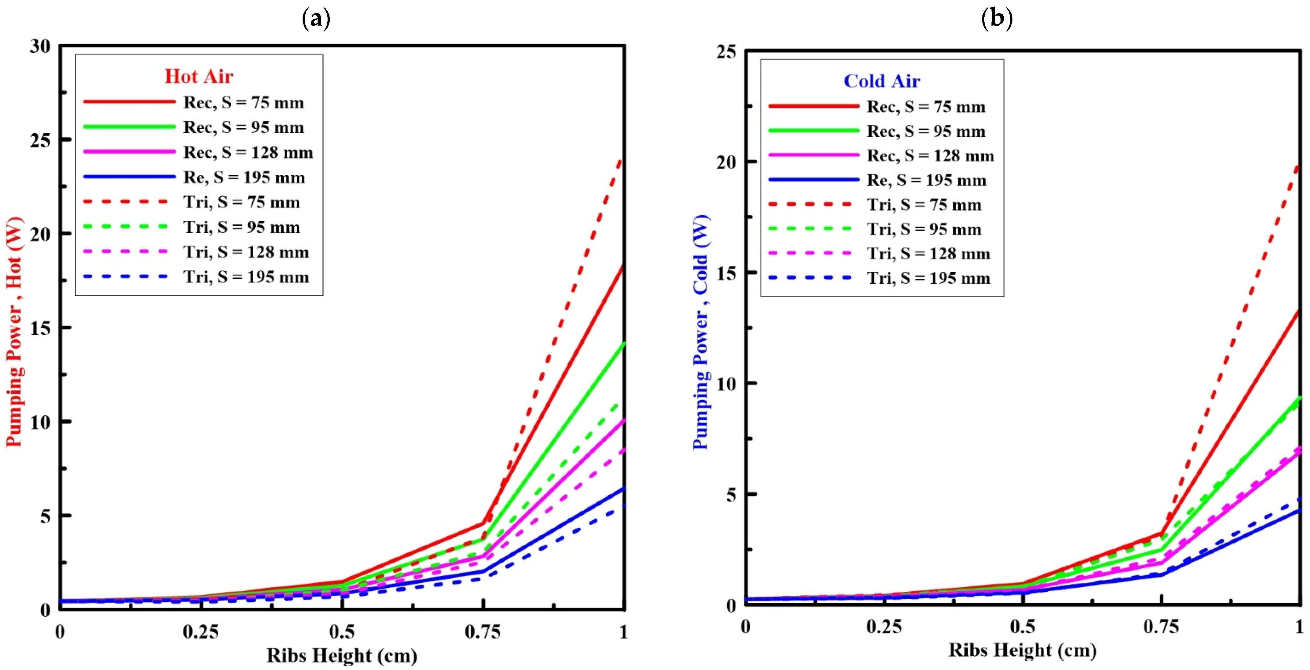
Figure 8 shows the pumping power variations through the channel of the hot and cold air sides with the rib height for different shapes of ribs. It can also be seen that the pumping power increases with the increase in rib height, and the maximum value occurs at 75 mm of rib spacing for the rectangular and triangular ribs.
For the hot and cold air sides, the pumping power for rectangular and triangular ribs almost has the same value and gradually increases with the rib height until it reaches 7.5 mm. At this rib height, there is a significant increase in the pumping power due to the big increase in the friction value.
It can be observed that increasing the rib’s height and number increases the turbulence intensity and velocity, which can improve the thermal performance of the flat plate heat exchanger. However, the enhancement of heat transfer by using ribs occurs with an increase in the friction value. Therefore, it is essential to calculate the thermal-hydraulic parameter, which combines the enhancement in the heat transfer and pressure drop due to friction through the channel, to obtain the best number and height of the cell.
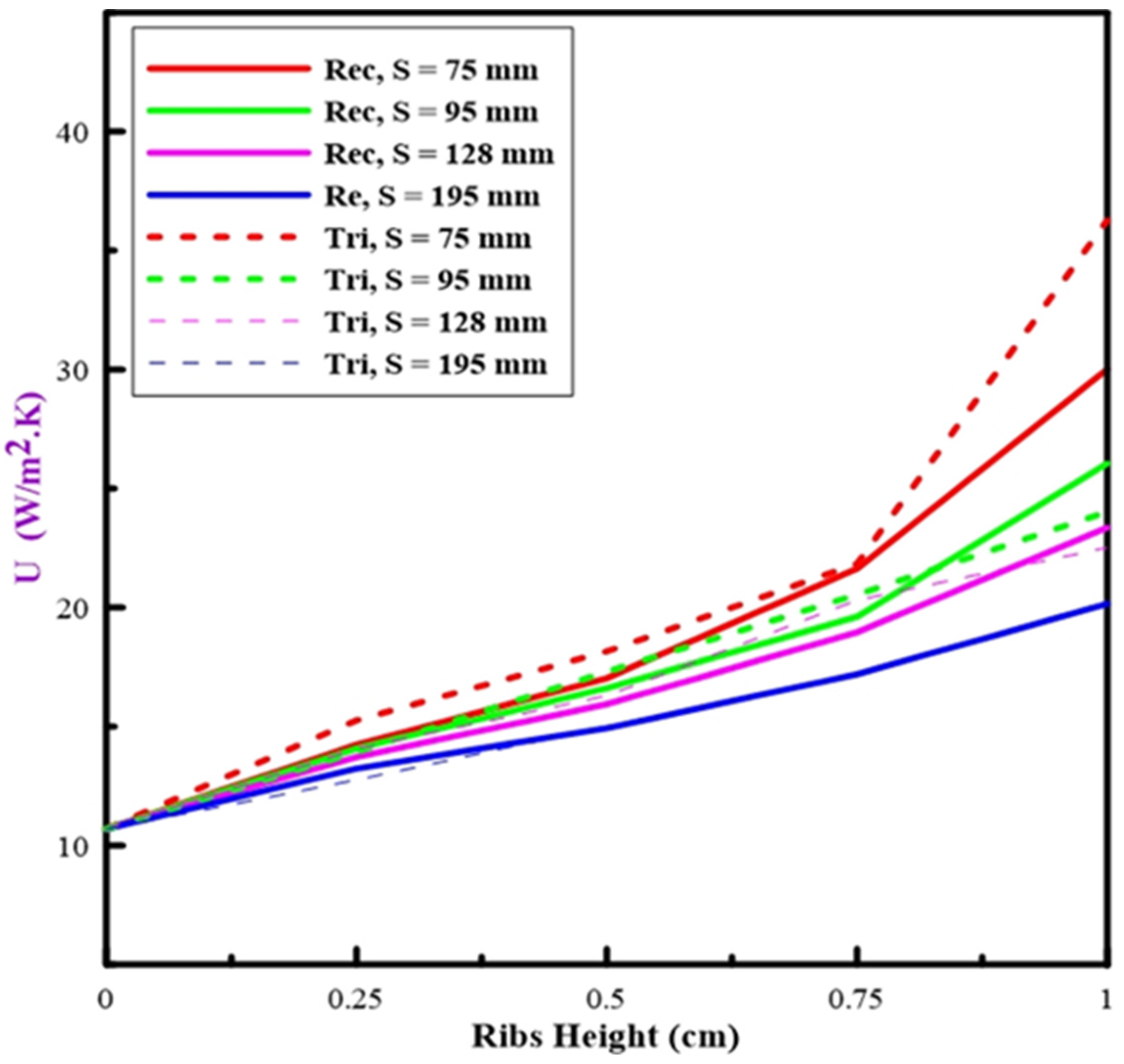
Figure 9 shows the disparity of the overall heat transfer coefficient at different heights of ribs, as the overall heat transfer coefficient increases when increasing the height of ribs. The overall heat transfer has a rapid increase after the rib height of 7.5 mm in both shapes due to the increase in the turbulence intensity in the fluid flow because of increasing the rib height. The overall heat transfer coefficient has a small increase with the rib height at the spacing of 195 mm in the two shapes of ribs. The other ribs’ spacings have slight differences between the triangular and rectangular ribs until reaching the 7.5 mm rib height. The overall heat transfer coefficient in the rectangular ribs is greater than the triangular ribs in the spacing cases of 95 and 128 mm due to the separation of the fluid in the triangular rib after this height. The spacing of 75 mm (5 ribs) creates a small distance between ribs, therefore the effect of fluid separation in triangular ribs decreases and has a higher overall heat transfer value than in rectangular ribs.
Figure 10 presents the thermal-hydraulic parameter with the rib’s height. With an increasing rib height, the thermal-hydraulic parameter increases until it reaches the highest value and then begins to decrease for both hot and cold airflow due to the increase in the value of the friction. At this point, the fiction value is higher than the improvement in the heat transfer rate.
The thermal-hydraulic parameter value with rectangular ribs is higher than the value of triangular shapes. The maximum thermal-hydraulic parameters are 1.62 and 1.84 for the hot and cold airflow at a height of 75 mm and a spacing of 95 mm, respectively. According to the previous results, ribs with a height and spacing of 75 mm and 95 mm, respectively, were selected as the optimal design for the flat plate heat exchanger.


