Abstract
Some of the major challenges facing micro-grids (MGs) during their connection with the utility grid are maintaining power system stability and reliability. One term that is frequently discussed in literature is the low-voltage ride-through (LVRT) capability, as it is required by the utility grid to maintain its proper operation and system stability. Furthermore, due to their inherent advantages, doubly fed induction generators (DFIGs) have been widely installed on many wind farms. However, grid voltage dips and distortion have a negative impact on the operation of the DFIG. A dynamic voltage restorer (DVR) is a commonly used device that can enhance the LVRT capability of DFIG compared to shunt capacitors and static synchronous compensator (STATCOM). DVR implements a series compensation during fault conditions by injecting the proper voltage at the point of common coupling (PCC) in order to preserve stable terminal voltage. In this paper, we propose a DVR control method based on the adaptive noise cancelation (ANC) technique to compensate for both voltage variation and harmonic mitigation at DFIG terminals. Additionally, we propose an online control of the DC side voltage of the DVR using pulse width modulation (PWM) rectifier to reduce both the size of the storage element and the solid-state switches of the DVR, aiming to reduce its overall cost. A thorough analysis of the operation and response of the proposed DVR is performed using MATLAB/SIMULINK under different operating conditions of the grid. The simulation results verify the superiority and robustness of the proposed technique to enhance the LVRT capability of the DFIG during system transients and faults.
1. Introduction
Since the early 1990s, the major power and utility companies have been facing many challenges because of the huge growth in electrical power consumption resulting from the increased population and their increasing inability to supply energy through existing transmission systems. Furthermore, environmental considerations have obliged electrical system designers to provide safer, reliable and less polluted energy systems. Therefore, the use of renewable energy resources (RES) is gaining great interest to meet these challenges [1]. Among various RES, wind energy is one of the most rapidly used [2,3], as announced by the global wind energy council (GWEC) that a capacity of 55 GW will be added to the global power system annually until 2023 [4]. Furthermore, according to the National Saudi Vision 2030, the production of electricity from RES will exceed 50% of the total country’s production [5]. Furthermore, the increased use of RES and conventional distributed generators (DGs) have introduced the concept of micro-grids (MGs), which have many benefits of reducing power losses, increasing power system reliability, reducing grid investment and delaying planned upgrades [6,7]. However, the increased penetration levels of DGs results in bidirectional power flows, creating many new challenges for distribution networks to be operated as active distribution networks, which may affect the stability and reliability of power grids and requires special attention when integrating a DG into the utility grid, as well as when the MG is forced to operate in the stand-alone mode when disconnected from the grid. Furthermore, increasing installation of wind turbines and large distributed generators can contribute to higher levels of fault current, as well as low voltage levels at terminals of wind turbines during fault. These impacts may lead to full interruption of wind turbines and, consequently, grid instability [8].
One of the most important terms to maintain power system stability is the LVRT capability during temporary system transients or faults. The concept of LVRT is based on the capability of DGs to stay connected to the utility grid during faults for predetermined duration. The loss of LVRT capability may contribute to the disconnection of wind turbine generators, causing a voltage drop and hence, system instability. Figure 1 presents the required LVRT operational limits that must be fulfilled by wind generators for different countries in Europe [9].
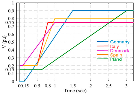
Figure 1.
LVRT capabilities for distributed generations in different countries.
DFIG, shown in Figure 2, is widely used in generating electrical power from wind energy. Its stator is connected directly to the utility grid, and the rotor is linked to the grid through two voltage source converters, which are the rotor-side converter (RSC) and the grid-side converter (GSC). The GSC is used to control the powers delivered as well as control the DC link voltage, while the RSC is used to maximize the power delivered to the power system.
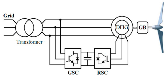
Figure 2.
Doubly fed induction generator-based wind turbine.
However, DFIG is very sensitive to disturbances from the utility grid due to the direct connection of both the stator and grid source converter (GSC) to the grid bus voltage. Any dip in the grid voltage may lead to an overcurrent in the rotor, which consequently results in an increase in DC link voltage and finally, protection tripping of the generator. In addition, the penetration level of the non-linear loads in power system generates voltage harmonics at PCC that cause serious distortions in DFIG stator and rotor currents as well as significant oscillations in stator power and electromechanical torque [10].
Therefore, as LVRT capability should be maintained during momentary system faults, several protection schemes along with control strategies are proposed in the literature to enhance the LVRT capability during system transients [11,12]. Using a crowbar in the rotor windings is one of the common methods to alleviate the DFIG from system disturbances as it limits the rotor currents [13]; however, it cannot provide the reactive power required by the utility grid while it is active [12]. In order to overcome some of the crowbar problems, a method using a chopper to regulate the DFIG DC link was proposed in [14,15]; however, it resulted in a circulation of high current in the rotor side converter (RSC) during utility disturbances. Shunt capacitors and STATCOMs have been proposed to enhance LVRT [16,17,18,19], but they cannot effectively deal with unsymmetrical faults. In [19], an LVRT enhancement strategy using DVR is proposed in [19], yet it suffers from increased control complexity and mathematical calculations.
The DVR, shown in Figure 3, was first commercially used in 1996 in Anderson, South Carolina, USA, with a voltage of 12.47 kV [20]. Many companies are currently producing DVRs for commercial use, and they are claiming that it can handle utility voltage dips of 70% in the nominal voltage and for a period up to 30 s and can be used for per-phase voltage and harmonics compensation. However, there are two main disadvantages associated with using the DVR, which are:
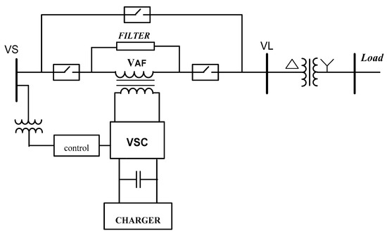
Figure 3.
DVR components and connection.
- ▪
- Expensive cost of its components as it needs a regulated DC source, inverter, injection transformer and passive filter.
- ▪
- The regulation circuit of the DC link may result in harmonics injection in the utility system.
An effective reduced rating of the DVR is a challenge that can be achieved with proper design of the system components, using advanced solid-state technology and precise control circuit. Furthermore, the DC link capacitor should be regulated but alleviate the system from any harmonic injection.
The main contributions of this paper can be summarized in the following points:
- A modified DVR topology is developed with a wind-driven DFIG to enhance the LVRT during voltage dips.
- A new DVR control method based on adaptive noise cancelation (ANC) technique to compensate for both voltage variation and harmonic mitigation at DFIG terminals is proposed.
- The DVR design is examined to assess its effectiveness under severe utility grid transients and variations of loads that have the same PCC.
- The performance of the proposed DVR is thoroughly investigated during critical and abnormal situations of the power system to precisely select the DVR component ratings to reduce its overall cost.
- The bidirectional active and reactive power flows among system components are investigated to assess the required ratings of DVR components and storage elements to effectively adjust any of the critical conditions facing the DFIG in a fast manner.
The organization of the manuscript is as follows. Section 2 introduces the description of the power system used for the case study. Section 3 explains the DVR circuit design and the online regulation of the DC link. Section 4 provides the proposed DVR control based on the ANC technique. The case study and simulation results are presented in Section 5 and Section 6, respectively. The conclusion is provided in Section 7.
2. Description of the Power System Used in the Study
The single-line diagram of the power system used in the current study is shown in Figure 4. The grid has a 25 kV, 50 Hz generating station. It is connected to the MG through a 132 kV transmission line. Furthermore, the MG has a local 20 MVA wind farm, which transmits its power through a 0.575/13.8 kV step-up transformer. The MG is feeding two loads using a 132/13.8 kV step-down transformer. The loads under study are described as follows:
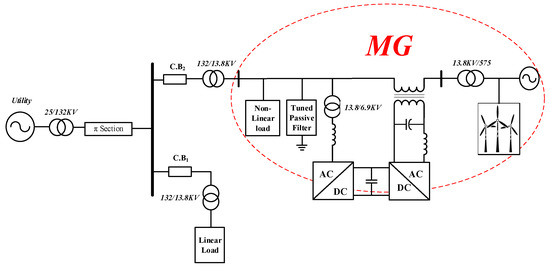
Figure 4.
Single-line diagram of the power circuit used in the study.
Load 1: 12.5 MVA linear inductive load.
Load 2: 10 MVA non-linear inductive load.
The control strategy and design of the DVR components are explained in detail in the following section.
3. DVR Circuit Design and DC Link Online Regulation
As shown in Figure 3, the DVR has three main components, which are:
- ▪
- Voltage source inverter with a series injecting transformer;
- ▪
- Energy storage capacitor with regulation circuit; and
- ▪
- Passive filter.
3.1. Voltage Source Inverter with A Series Injecting Transformer
The energy storage element is supplying a DC voltage which is being converted by the employed voltage source inverter (VSI) to an AC voltage and then injected into the power circuit system through a series injecting transformer to the equipment to be protected [21]. In the current work, the hysteresis voltage control technique is adopted to generate the required signals for the VSI solid-state switches to generate the voltage, in shape and magnitude, required for voltage compensation. The compensation is achieved through the power exchange to or from the DVR to alter the voltage magnitude and phase. Different voltage compensation methodologies were discussed in literature and the most commonly used techniques are pre-sag voltage compensation technique and in-phase voltage compensation technique [22,23,24], which are described in Figure 5.
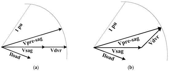
Figure 5.
Voltage compensation techniques of DVR: (a) in-phase voltage compensation methodology, (b) pre-sag voltage compensation methodology.
Each of the aforementioned voltage compensation methods has its merits over the other. On one hand, the performance of the pre-sag methodology is claimed to be better than the in-phase methodology when nonlinear loads are employed within the MG or close to the PCC [25], since it requires high voltage compensation from the DVR during normal operation, which increases the switching elements and stresses. Therefore, it is preferred not to use the DVR during normal conditions, where it can be achieved by bypassing the injecting transformer or otherwise employing a transformer with very low leakage reactance to minimize the resulted voltage drop [25]. On the other hand, the in-phase technique may require a higher jump in the voltage supplied from the DVR from almost zero voltage magnitude to the compensation voltage magnitude required to retain the nominal grid voltage, contrary to the pre-sag compensation methodology, which requires less voltage compensation.
3.2. Energy Storage Capacitor with a Regulation Circuit
As the VSI is responsible for controlling and compensating the voltage in a fast manner during the power system interruption and abnormalities, it should have an efficient and reliable power storage element. The main requirement of the storage element is to always provide a voltage above the peak of the required reference compensation voltage to maintain the controllability of the VSI. However, it is essential to reduce the size of the storage element in order to decrease the DVR cost, which can be achieved by controlling the voltage generated from it to a relatively low value while keeping its effective operated function. Different controlling circuits are used in literature to control the voltage of the storage element, such as using a DC chopper with a bridge diode rectifier [26]. However, this circuit suffers from drawing harmonic currents from the grid and thus increases the injected THD in the power system. In this work, the storage element of DVR is supplied and controlled using a PWM rectifier, which can be connected to the utility grid, as shown in Figure 6.
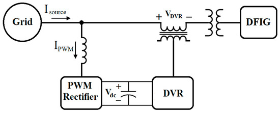
Figure 6.
Single-line diagram of the DVR and PWM rectifier regulation circuit.
The main purpose of the PWM rectifier is to always keep the DVR capacitor voltage magnitude greater than the required reference compensation voltage while drawing only almost sinusoidal current, free from harmonics, from the grid. Moreover, this current should be in phase with grid voltage to ensure a unity power factor. The topology of the three-phase voltage-source PWM rectifier is shown in Figure 7. The input side is connected to the grid through a line reactor, whereas the output side is shunted by a capacitor, Cdc, which is being used as the DC source for the DVR.
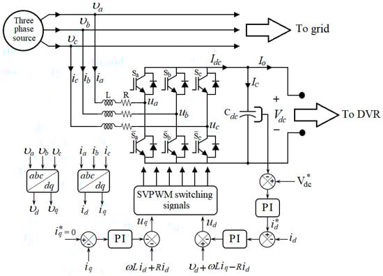
Figure 7.
PWM rectifier topology and control.
The stationary reference frame (abc) is transformed into a rotating reference frame (dq) to ensure that the input currents to the PWM rectifier (ia,b,c) are sinusoidal by synchronizing the dq axes with a sinusoidal reference [27]. If the grid voltage (va,b,c) is assumed to be balanced, and by applying Kirchhoff’s laws to the PWM rectifier circuit, the mathematical model in the three-phase stationary reference frame can be expressed as follows:
where ua,b,c is the voltage at the entry points of the PWM rectifier, which can be extracted from:
where Sa,b,c are the switching signals to the PWM rectifier circuit. Furthermore, the DC-side current (Idc) and capacitor current (Ic) can be derived as follows:
where Io is the input current to the DVR circuit. Considering a symmetrical three-phase system, the abc three-phase stationary reference frame can be transformed into a dq rotating reference frame according to the following transformation matrix:
where X represents the voltage or current variables and θ = ωt is the angle between the a-axis and the d-axis. Thus, the time-invariant voltage (Equation (1)) and current (Equation (4)) of the PWM rectifier circuit can be obtained in the dq rotating frame as:
According to Equation (6), the dq rotating reference frame equivalent circuits of the PWM rectifier can be obtained as shown in Figure 8.
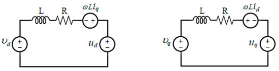
Figure 8.
PWM rectifier equivalent circuits in a dq rotating frame.
Since the grid voltage is assumed to be balanced, the quadrature component (vq) is equal to zero. In addition, the direct and quadrature components of the line current, id and iq, have zero derivative values as they are constant in steady-state operation. Thus, the steady-state control function of PWM rectifier can be simplified from Equation (6) as:
Equation (8) is the base of the control circuit, and it is modified with a PI controller to ensure the proper online regulation of the DC link voltage as well as a sinusoidal line current of PWM rectifier. The DC link voltage is controlled using the PI gains (kv−p, kv−i) to generate the reference current , while the PI gains (ki−p, ki−i) are used to generate ud and uq as follows:
Finally, the obtained ud and uq are applied to SVPWM to generate the required switching signals to the power circuit. Moreover, the design of the PWM rectifier can be further improved by controlling the voltage ripple of the DC link capacitor to limit the size of the capacitor, hence reducing the overall cost of the DVR. If the peak voltage ripple, ΔVdc, is limited to certain allowable constraints and the switching frequency is specified according to the required power and the allowable switching losses, the minimum value of the capacitor size can be found as [28]:
By relating the peak supply current to the output power, the required capacitor value is:
3.3. Passive Filters
3.3.1. DVR Passive Filter
A low-pass passive filter is required to be installed at the front end of the DVR to remove the higher-order harmonics generated from the VSI, minimize the distortion in the output voltage and reduce the transformer rating [29]. The cut-off frequency of the low-pass filter can be determined using the equivalent circuit of the DVR circuit shown in Figure 9, where Vinv is output voltage of the inverter and Rf, Lf and Cf are the resistance, inductance and capacitance of the filter, respectively.
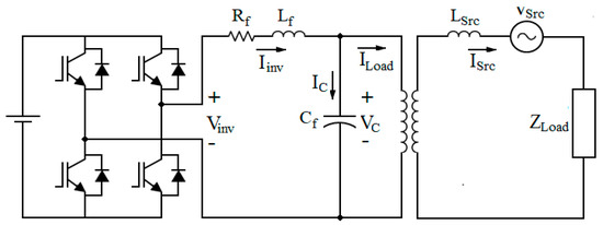
Figure 9.
Equivalent circuit of DVR with a low-pass filter.
According to Figure 9, the transfer function of a LC filter can be derived as:
.
If the filter cut-off frequency ωf is given, the filter components can be precisely determined using Equation (12).
3.3.2. Shunt Passive Filter
A shunt passive filter is used in parallel with the DVR to sink all harmonic currents generated by non-linear load. This filter can be tuned due to the most significant harmonics (i.e., 5th, 7th) as well as the higher-order harmonics.
4. Proposed DVR Control Using ANC Technique
The proposed DVR controller provides two main functions: the first function is to enhance the LVRT capability of the DFIG, while the second function is to block the harmonic currents generated by the non-linear load to penetrate into DFIG windings. The principle of ANC is shown in Figure 10, in which a signal s is separated from additive noise n0 [30]. It has two inputs: s + n0 is the primary and n1 is the reference input. There is no correlation between signals s and n0, as well as s and n1. However, both signals n1 and n0 are correlated. In Figure 10, an adaptive filter is used to generate a reference noise signal , which is typical to n0, while system output y is considered as an actuating error signal e to adjust the filter parameters. Thus, n0 is canceled and system output y is free from noise.
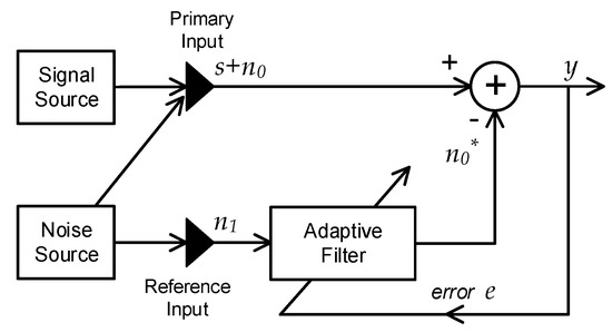
Figure 10.
Block diagram of the ANC technique.
In this paper, ANC is implemented as shown in Figure 11 to extract the harmonic components from the load current and to inject it into the DVR control loop in such a way to block it from the DFIG circuit. The non-linear load current can be expressed as:
where corresponds to the fundamental component, presents the harmonic component and and represent active and reactive components, respectively. Here, the load current is used as a primary input, while the reference input is obtained by a sinusoidal signal , which is synchronized with the grid utility voltage.
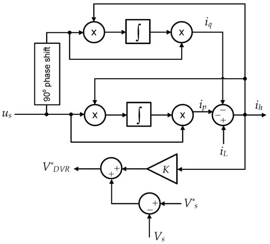
Figure 11.
DVR control circuit using the ANC technique.
According to Figure 12, the DVR injects a voltage harmonic as:
where is the supply current harmonics drawn by the non-linear load. The following equations can be presented:
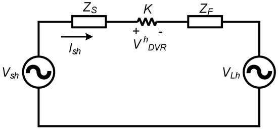
Figure 12.
Single-phase equivalent circuit of DVR components with respect to harmonics.
If gain K is designed so that K >> ZS + ZF, Equations (15) and (16) can be rewritten as:
According to Equation (18), it can be concluded that DVR injects a harmonic voltage that compensates for load voltage harmonics to keep the utility voltage at PCC sinusoidal.
5. Proposed System Performance
The power system shown in Figure 4 is modeled using MATLAB/SIMULINK to assess the effectiveness of the proposed DVR during different operating conditions. The system model is shown in Figure 13. The parameters of the DFIG, DVR, PWM rectifier and passive filters, which are used to simulate the system, are described in Table 1.
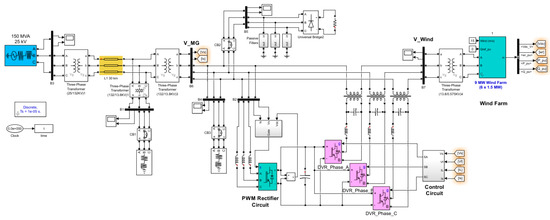
Figure 13.
MATLAB/SIMULINK model of the studied system.

Table 1.
Power system parameters.
- The DC link capacitor voltage of the DVR is regulated at 7 kV.
- The low-pass filter of the VSI is designed to have a cut-off frequency of 450 Hz using a 52 μF filter capacitor and 2.4 mH filter inductor.
- The rated power of the series-injecting transformer is 5 MVA and its turns ratio is (1:1).
6. Simulation Results
In order to investigate the performance of the proposed control techniques, the capability and effectiveness of the proposed DVR circuit in improving the LVRT capability of the DFIG during a symmetrical sag disturbance is examined in this section. Then, the system is examined under distorted grid voltage caused by non-linear loads. The German LVRT profile is adopted in the simulation, as shown in Figure 14. The German LVRT code addresses that the DFIG voltage should recover to 90% of its nominal voltage within about 1.5 s. It also shows that the power system is subjected to a 40% symmetrical sag starting at t = 2.5 s and lasts for 0.9 s.
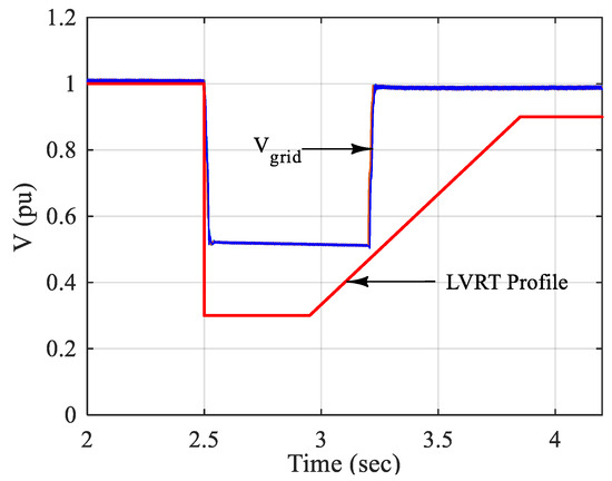
Figure 14.
Adopted German LVRT voltage profile and grid voltage (p.u.).
Figure 15 and Figure 16 show the DFIG terminal voltage, waveforms and RMS value without and with the DVR employed, respectively. As the grid voltage sag occurs within the LVRT voltage profile, the DFIG should not respond to this system abnormality and keep its proper operation to keep the power system stability. Moreover, these figures reveal that when DVR is not employed, the DFIG voltage decreases abruptly in a very sharp manner, and consequently, the DFIG may lose its stability depending on the DFIG and power system parameters, where this action cannot comply with the LVRT requirements of the utility grid. However, the situation is completely changed by employing the DVR, which could alleviate the DFIG from the transient’s effects of the power system and keep the DFIG voltage stable.
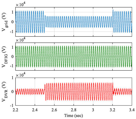
Figure 15.
DFIG terminal voltage (signals) of the DFIG when subjected to symmetrical voltage sag.
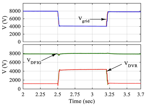
Figure 16.
DFIG terminal voltage (RMS) of the DFIG when subjected to symmetrical voltage sag.
Figure 17 and Figure 18 show the DFIG stator and rotor currents’ response when the system is subjected to a symmetrical voltage sag with and without using the DVR. The limit of the currents should not exceed 2.0 p.u. [31,32]. Although the stator and rotor currents do not exceed these limits when not employing the DVR, as shown in Figure 17, using the DVR control circuit could enable the DFIG to respond in a very fast manner, suppress any high transient currents, keep the current values to almost the rated value of the DFIG and alleviate the power system from any instability that may arise from these transients.
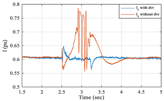
Figure 17.
Stator current (RMS) of the DFIG when subjected to a symmetrical voltage sag.
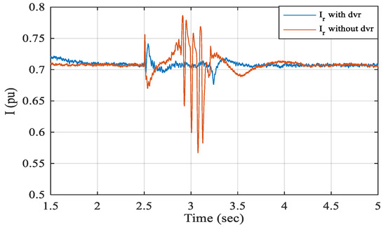
Figure 18.
Rotor current (RMS) of the DFIG when subjected to a symmetrical voltage sag.
Figure 19 shows the active and reactive powers generated/absorbed from DFIG with and without using the DVR when the power system is subjected to symmetrical voltage sag. The data recorded in Table 2 were obtained from the figure at the end of the sag period. From the table, it can be concluded that the DVR could enable the DFIG to work effectively in a stable manner during the sag period and generate the active and reactive powers required, which is not the case when not using the DVR, as the active power generated from the DFIG drops sharply to almost zero and the generator must be islanded and disconnected if the sag persists. Furthermore, the reactive power of the DFIG has a fluctuating manner from increasing to decreasing from the steady-state value, which may lead to instability issues in the system. Moreover, the DVR could help the DFIG in generating more active power and absorbing less reactive power in normal conditions by improving the voltage profile of the system.
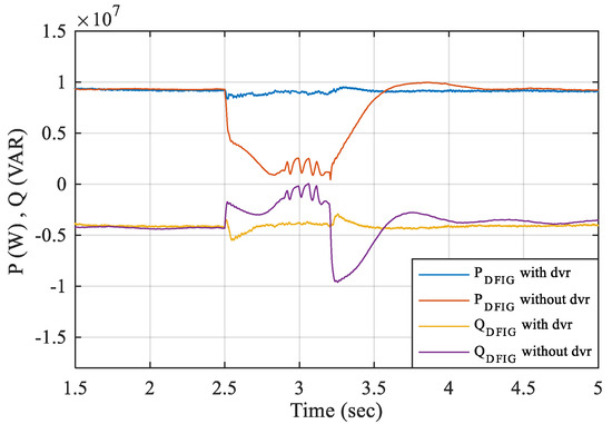
Figure 19.
Active and reactive powers of the DFIG with and without using the DVR when the system is subjected to symmetrical voltage sag.
Table 2.
DFIG P and Q with DVR and without DVR.
To examine and clarify the importance of using the DVR in enhancing the LVRT of the system, a plot of active powers generated/absorbed by different system components is shown in Figure 20, when the system is subjected to symmetrical voltage sag. The recorded data in Table 3 were extracted from Figure 20 at the end of the sag period. It can be concluded that the DVR could help the DFIG to provide its full required active power and maintain the system stability.
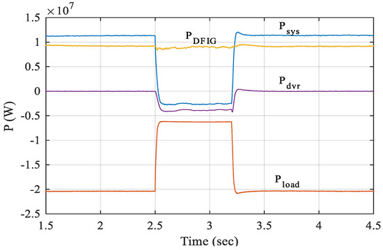
Figure 20.
Active powers of the system under simulation when using the DVR when the system is subjected to symmetrical voltage sag.
Table 3.
Active powers of different system components.
In the same manner, performance can be observed from Figure 21 and Table 4 showing the reactive power generated or absorbed from different system components. It is worth mentioning that the DVR can be considered as a zero-power consumption device, as it consumes and injects the same powers to the system.
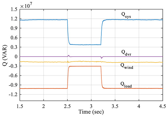
Figure 21.
Reactive powers of the system under simulation when using the DVR when the system is subjected to symmetrical voltage sag.
Table 4.
Reactive powers of the different system components.
Moreover, as mentioned in the literature that the electromechanical torque does not exceed 2–2.5 p.u [33] during system disturbances, a study of the electromechanical torque is carried out, as shown in Figure 22. This figure confirms the proper action of the DVR in keeping the DFIG working normally even with significant sag in the system, which is not the case when not using the DVR.
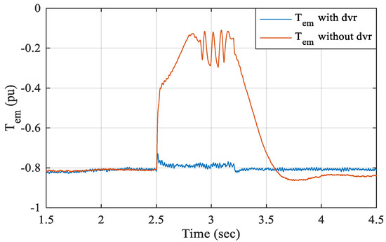
Figure 22.
Electromechanical torque of the DFIG with and without using the DVR when the system is subjected to symmetrical voltage sag.
One of the biggest advantages of using the DVR over other devices is its superior ability to deal with unsymmetrical voltages [34,35]. To assess this ability and investigate the enhancement of the LVRT of the DFIG when using the DVR, large unsymmetrical loads located at the PCC were turned on and off, which led to unsymmetrical sags in the system. Figure 23 and Figure 24 show the grid, DFIG and DVR terminal voltage waveforms and RMS values with the DVR employed, respectively. Both figures confirm that employing the DVR could correct independent phases of the DFIG from the transient’s effects of the power system and keep the voltage of DFIG stable and consequently enhancing the LVRT ability. Furthermore, Figure 25 confirms the ability of the DVR to keep the DFIG in injecting the required active and reactive powers in unsymmetrical conditions.
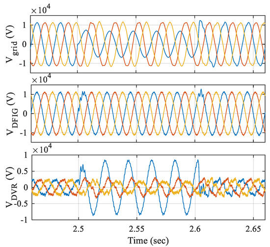
Figure 23.
DFIG terminal voltage (signals) of the DFIG when subjected to unsymmetrical voltage sag.
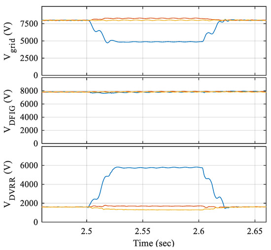
Figure 24.
DFIG terminal voltage (RMS) of the DFIG when subjected to unsymmetrical voltage sag.
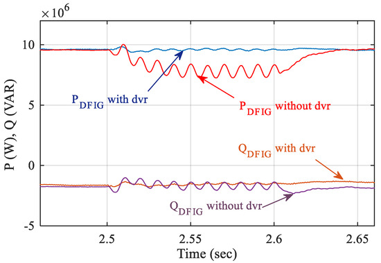
Figure 25.
Active and reactive powers of the DFIG with and without using the DVR when the system is subjected to symmetrical voltage sag.
As shown in Figure 26, connecting a non-linear load to MG causes a distortion in grid voltage with a THD of 21.9%. The effect of grid voltage distortion on DFIG performance is shown in Figure 26. The THDs of the DFIG stator and rotor currents are 13.36% and 14.28%, respectively. The electromechanical torque has a ripple of 24%, causing a nonuniform heating in both stator and rotor windings of DFIG, as well as oscillations in electromechanical torque.
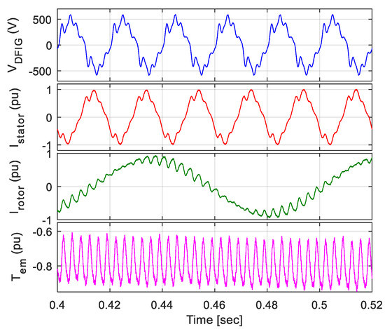
Figure 26.
Stator voltage, stator current, rotor current and electromechanical torque of DFIG under distorted grid voltage.
The application of DVR significantly improves the performance of DFIG, as shown in Figure 27. Table 5 includes the THD values of the voltage, current and torque of the DFIG. The grid voltage THD is reduced to 2.15%, while the THD of stator and rotor currents are reduced to 2% and 2.82%, respectively. In addition, the ripple of electromechanical torque is reduced to 5%.
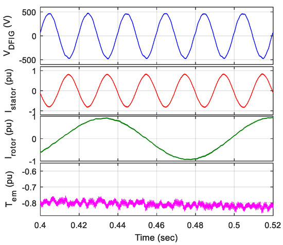
Figure 27.
Stator voltage, stator current, rotor current and electromechanical torque of DFIG using DVR under distorted grid voltage. For a clear comparison, Table 5 summarizes these results.
Table 5.
Comparing the DFIG performance under grid voltage distortion.
The use of the DVR to maintain the LVRT can be further improved by reducing its cost. This can be achieved by decreasing the switching element ratings and the DC link capacitor size. Three main parameters of the DVR are controlled simultaneously to enable the proper choice of the switches voltage rating and storage element size; they are DC link voltage rating, the percentage sag in power system and the size of the DC link capacitor. Figure 28 provides detailed values for the three parameters.
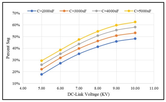
Figure 28.
DC link capacitor voltage versus percent power system sag at different capacitor sizes.
The cost analysis breakdown of the proposed system depends on the design of the three-phase PWM boost rectifier, the electrolytic capacitor size and the PWM inverter. The designs of the three-phase PWM boost rectifier, the capacitor size and the PWM inverter have been addressed in many references in the literature [28,29]. However, selecting the appropriate size of the DC link capacitor in this paper is developed based on simulation. The design uses a two-step approach. First, by fixing the capacitor size, the DC link voltage is reduced until the DVR cannot compensate the specified voltage sag. Second, the DC link voltage is fixed on the minimum value derived in the first step and the capacitor size is reduced until the DVR cannot compensate the desired voltage sag. Then, the values of the minimum capacitor and voltage are recorded. These steps are repeated with different link capacitors and voltages, as shown in Figure 28. This figure reveals that the DC link voltage of the DVR should be maintained at 7.3 kV for a 50% sag in the grid when using a capacitor of 5000 μF. Furthermore, to decrease the solid-state switching elements size, the DC link voltage must be decreased, and it is inversely proportional to the capacitor size.
Therefore, the capacitor size can be selected for certain voltage sag using Figure 28, which can be used as settings for the DVR. Finally, it should be mentioned that the DC link voltage must be kept greater than the input voltage of the DVR input rectifier, Vs-rect, to keep the sinusoidal shape of the current drawn from the grid, as shown in Figure 29.
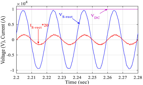
Figure 29.
The PWM rectifier voltage, Vs-rect, DC link capacitor voltage, VDC and PWM rectifier input current, Is-rect.
However, as the PWM rectifier may consume considerable power from the power system, especially when the grid is subjected to disturbances, special attention should be paid to power supplied by the PWM rectifier, as it acts as an extra load to the grid and may limit its capability in supporting the actual system loads, leading to instability.
7. Conclusions
In this paper, we propose an LVRT enhancement technique for a DFIG-based wind turbine using a DVR topology. A detailed design of the DVR components along with the control circuit based on a mathematical model is provided. The proposed DVR circuit and its ANC control strategy are examined during symmetrical and unsymmetrical voltage sags as well as voltage distortion at the PCC. The DFIG’s active power, reactive power, stator current, rotor current and electromechanical torque are recorded to assess the effect of the proposed DVR on the LVRT capability and mitigate the effect of harmonic distortion to the DFIG.
The proposed DVR has effectively controlled its voltage and powers in a fast manner to adapt to any disturbance in the grid voltage, keeping the DFIG currents at safe limits and maintaining almost a constant electromechanical torque to keep the DFIG working within the required limits to enhance the LVRT during system abnormalities. Furthermore, the PWM rectifier could provide the DC link capacitor with the required energy to keep it within the required working limits, drawing only a sinusoidal current free from harmonics from the utility grid to alleviate the system from any extra harmonics injected to it. Finally, set of waveforms relating the DC link voltage rating, the percentage sag in power system and the size of the DC link capacitor is provided, which can be used to select a smaller size of DC link capacitor and limit the required DC voltage to small magnitudes while keeping the proper effective operation of the DVR and thus significantly decreasing the overall DVR cost.
Author Contributions
Conceptualization, M.A.A. and T.K.; methodology, M.A.A. and E.M.A.; software, M.A.A. and T.K.; validation, M.A.A., T.K. and E.M.A.; formal analysis, M.A.A.; investigation, E.M.A.; resources, T.K.; data curation, M.A.A.; writing—original draft preparation, T.K.; writing—review and editing, E.M.A.; visualization, E.M.A.; supervision, T.K.; project administration, T.K.; funding acquisition, M.A.A. All authors have read and agreed to the published version of the manuscript.
Funding
The authors extend their appreciation to the Deanship of Scientific Research at Jouf University for funding this work through research grant no. DSR 2020-02-476.
Institutional Review Board Statement
Not applicable.
Informed Consent Statement
Not applicable.
Data Availability Statement
Not applicable.
Conflicts of Interest
The authors declare no conflict of interest.
References
- Owusu, P.A.; Asumadu-Sarkodie, S. A review of renewable energy sources, sustainability issues and climate change mitigation. Cogent Eng. 2016, 3, 1167990. [Google Scholar] [CrossRef]
- Askarian, I.; Eren, S.; Pahlevani, M.; Knight, A.M.; Knight, A. Digital Real-Time Harmonic Estimator for Power Converters in Future Micro-Grids. IEEE Trans. Smart Grid 2017, 9, 6398–6407. [Google Scholar] [CrossRef]
- Kandil, T.; Ahmed, M.A. Control and Operation of Dynamic Voltage Restorer with Online Regulated DC-Link Capacitor in Microgrid System. Can. J. Electr. Comput. Eng. 2020, 43, 331–341. [Google Scholar] [CrossRef]
- Qin, B.; Li, H.; Zhou, X.; Li, J.; Liu, W. Low-Voltage Ride-Through Techniques in DFIG-Based Wind Turbines: A Review. Appl. Sci. 2020, 10, 2154. [Google Scholar] [CrossRef]
- Alotaibi, Z.S.; Khonkar, H.I.; Al Amoudi, A.O.; Alqahtani, S.H. Current status and future perspectives for localizing the solar photovoltaic industry in the Kingdom of Saudi Arabia. Energy Transit. 2020, 4, 1–9. [Google Scholar] [CrossRef]
- Zia, M.F.; Elbouchikhi, E.; Benbouzid, M. Microgrids energy management systems: A critical review on methods, solutions, and prospects. Appl. Energy 2018, 222, 1033–1055. [Google Scholar] [CrossRef]
- Alotaibi, I.; Abido, M.A.; Khalid, M.; Savkin, A.V. A Comprehensive Review of Recent Advances in Smart Grids: A Sustainable Future with Renewable Energy Resources. Energies 2020, 13, 6269. [Google Scholar] [CrossRef]
- Kamarposhti, M.A.; Mozafari, S.B.; Soleymani, S.; Hosseini, S.M. Improving the wind penetration level of the power systems connected to doubly fed induction generator wind farms considering voltage stability constraints. J. Renew. Sustain. Energy 2015, 7, 043121. [Google Scholar] [CrossRef]
- Benali, A.; Khiat, M.; Allaoui, T.; Denai, M. Power Quality Improvement and Low Voltage Ride Through Capability in Hybrid Wind-PV Farms Grid-Connected Using Dynamic Voltage Restorer. IEEE Access 2018, 6, 68634–68648. [Google Scholar] [CrossRef]
- Xu, H.; Hu, J.; He, Y. Operation of Wind-Turbine-Driven DFIG Systems Under Distorted Grid Voltage Conditions: Analysis and Experimental Validations. IEEE Trans. Power Electron. 2011, 27, 2354–2366. [Google Scholar] [CrossRef]
- Gkavanoudis, S.I.; Demoulias, C.S. A control strategy for enhancing the Fault Ride-Through capability of a microgrid during balanced and unbalanced grid voltage sags. Sustain. Energy Grids Netw. 2015, 3, 1–11. [Google Scholar] [CrossRef]
- Xie, D.; Xu, Z.; Yang, L.; Østergaard, J.; Xue, Y.; Wong, K.P. A Comprehensive LVRT Control Strategy for DFIG Wind Turbines with Enhanced Reactive Power Support. IEEE Trans. Power Syst. 2013, 28, 3302–3310. [Google Scholar] [CrossRef]
- Justo, J.J.; Ro, K.-S. Control strategies of doubly fed induction generator-based wind turbine system with new rotor current protection topology. J. Renew. Sustain. Energy 2012, 4, 43123. [Google Scholar] [CrossRef]
- Pereira, R.; Pereira, A.J.C.; Ferreira, C.M.; Barbosa, F.P.M. Influence of Crowbar and Chopper Protection on DFIG during Low Voltage Ride Through. Energies 2018, 11, 885. [Google Scholar] [CrossRef]
- Pannell, G.; Zahawi, B.; Atkinson, D.J.; Missailidis, P. Evaluation of the Performance of a DC-Link Brake Chopper as a DFIG Low-Voltage Fault-Ride-Through Device. IEEE Trans. Energy Convers. 2013, 28, 535–542. [Google Scholar] [CrossRef]
- Hossain, J.; Pota, H.; Ugrinovskii, V.A.; Ramos, R. Simultaneous STATCOM and Pitch Angle Control for Improved LVRT Capability of Fixed-Speed Wind Turbines. IEEE Trans. Sustain. Energy 2010, 1, 142–151. [Google Scholar] [CrossRef]
- Molinas, M.; Suul, J.A.; Undeland, T. Low Voltage Ride Through of Wind Farms with Cage Generators: STATCOM versus SVC. IEEE Trans. Power Electron. 2008, 23, 1104–1117. [Google Scholar] [CrossRef]
- Yunus, A.M.S.; Masoum, M.A.S.; Abu-Siada, A. Effect of STATCOM on the Low-Voltage-Ride-through Capability of Type-D Wind Turbine Generator; IEEE PES Innovative Smart Grid Technologies: Perth, WA, Australia, 2011; pp. 1–5. [Google Scholar]
- Falehi, A.D.; Rafiee, M. Maximum efficiency of wind energy using novel Dynamic Voltage Restorer for DFIG based Wind Turbine. Energy Rep. 2018, 4, 308–322. [Google Scholar] [CrossRef]
- Ghosh, A.; Ledwich, G. Structures and control of a dynamic voltage regulator (DVR). In Proceedings of the 2001 IEEE Power Engineering Society Winter Meeting. Conference Proceedings (Cat. No.01CH37194), Columbus, OH, USA, 28 January–2 February 2002; Volume 3, pp. 1027–1032. [Google Scholar]
- Helal, A.A.; Saied, M.H. Dynamic voltage restorer adopting 150° conduction angle VSI. In Proceedings of the 2009 IEEE Electrical Power & Energy Conference (EPEC), Montreal, BC, Canada, 22–23 October 2009; pp. 1–6. [Google Scholar]
- Padiyar, K.R. FACTS Controllers in Power Transmission and Distribution; New Age International (P) Limited: New Delhi, India, 2007; ISBN 9788122421422. [Google Scholar]
- Kim, H.; Kim, J.H.; Sul, S.K. A design consideration of output filters for dynamic voltage restorers. In Proceedings of the 2004 IEEE 35th Annual Power Electronics Specialists Conference (IEEE Cat. No. 04CH37551), Aachen, Germany, 20–25 June 2004; Volume 6, pp. 4268–4272. [Google Scholar] [CrossRef]
- Choi, S.S.; Li, J.D.; Vilathgamuwa, D.M. A Generalized Voltage Compensation Strategy for Mitigating the Impacts of Voltage Sags/Swells. IEEE Trans. Power Deliv. 2005, 20, 2289–2297. [Google Scholar] [CrossRef]
- Abas, N.; Dilshad, S.; Khalid, A.; Saleem, M.S.; Khan, N. Power Quality Improvement Using Dynamic Voltage Restorer. IEEE Access 2020, 8, 164325–164339. [Google Scholar] [CrossRef]
- Jowder, F. Design and analysis of dynamic voltage restorer for deep voltage sag and harmonic compensation. IET Gener. Transm. Distrib. 2009, 3, 547–560. [Google Scholar] [CrossRef]
- He, S.; Xiong, J.; Dai, D. Modeling and Stability Analysis of Three-Phase PWM Rectifier. In Proceedings of the 2018 IEEE International Power Electronics and Application Conference and Exposition (PEAC), Shenzhen, China, 4–7 November 2018; pp. 1–5. [Google Scholar]
- Kwak, S.; Toliyat, H. Design and Rating Comparisons of PWM Voltage Source Rectifiers and Active Power Filters for AC Drives with Unity Power Factor. IEEE Trans. Power Electron. 2005, 20, 1133–1142. [Google Scholar] [CrossRef]
- Vilathgamuwa, D.M.; Perera, A.; Choi, S. Voltage sag compensation with energy optimized dynamic voltage restorer. IEEE Trans. Power Deliv. 2003, 18, 928–936. [Google Scholar] [CrossRef]
- Wang, Q.; Wu, N.; Wang, Z. A neuron adaptive detecting approach of harmonic current for APF and its realization of analog circuit. IEEE Trans. Instrum. Meas. 2001, 50, 77–84. [Google Scholar] [CrossRef]
- Ran, L.; Xiang, D.; Tavner, P.; Yang, S. Control of a doubly fed induction generator in a wind turbine during grid fault ride-through. In Proceedings of the 2006 IEEE Power Engineering Society General Meeting, Montreal, QC, Canada, 18–22 June 2006; p. 1. [Google Scholar]
- Rahimi, M.; Parniani, M. Transient Performance Improvement of Wind Turbines with Doubly Fed Induction Generators Using Nonlinear Control Strategy. IEEE Trans. Energy Convers. 2009, 25, 514–525. [Google Scholar] [CrossRef]
- Rahmann, C.; Haubrich, H.-J.; Moser, A.; Palma-Behnke, R.; Vargas, L.; Salles, M.B.C. Justified Fault-Ride-Through Requirements for Wind Turbines in Power Systems. IEEE Trans. Power Syst. 2011, 26, 1555–1563. [Google Scholar] [CrossRef]
- Ghosh, A.; Jindal, A.; Joshi, A. Design of a Capacitor-Supported Dynamic Voltage Restorer (DVR) for Unbalanced and Distorted Loads. IEEE Trans. Power Deliv. 2004, 19, 405–413. [Google Scholar] [CrossRef][Green Version]
- Soomro, D.M.; Keat, Y.W.; Baloch, M.H.; Abdullah, M.N.; Radzi, N.H.M.; Memon, Z.A. Mitigation of Voltage Sag Caused by Unbalanced Load by Using DFT Controlled DVR. In Proceedings of the 2019 IEEE International Conference on Innovative Research and Development (ICIRD), Jakarta, Indonesia, 28–30 June 2019; pp. 1–6. [Google Scholar]
Publisher’s Note: MDPI stays neutral with regard to jurisdictional claims in published maps and institutional affiliations. |
© 2022 by the authors. Licensee MDPI, Basel, Switzerland. This article is an open access article distributed under the terms and conditions of the Creative Commons Attribution (CC BY) license (https://creativecommons.org/licenses/by/4.0/).