Article

Study on Overburden Structure Characteristics and Induced Scour Mechanisms of Horizontal Sublevel Mining in Steep and Extra-Thick Coal Seams

1
School of Mines, China University of Mining and Technology, Xuzhou 221116, China
2
Yaojie Coal Power Group Co., Ltd., Lanzhou 730080, China
3
State Key Laboratory of Coal Resources and Safe Mining, Xuzhou 221116, China
*
Authors to whom correspondence should be addressed.
Sustainability 2022, 14(19), 11980; https://doi.org/10.3390/su141911980
Submission received: 29 July 2022 / Revised: 14 September 2022 / Accepted: 15 September 2022 / Published: 22 September 2022

Abstract

:
In order to study the space–time evolution law and the induced impact mechanism of overburden breaking in the tangential horizontal sublevel during the fully mechanized mining of extra-thick and steep coal seams, we took the Yaojie No. 3 mine as an example. Through the establishment of an overburden breaking mechanical model, the structural characteristics of hinged rock beams after overburden breaking and the space–time evolution law of overburden structure instability were analyzed, the static and dynamic load conditions that induce rockbursts were analyzed, and the induced impact mechanism of dynamic and static load superposition was revealed. Our research showed that, due to the asymmetry of the roof and floor, the coal body in the working face is in the strong shear stress zone at the end of the air inlet roadway, which easily produces shear failure. The lateral support pressure and the shear stress of the coal body in the goaf are the static load sources of the rockburst in the steep coal seam; after the roof overburden is broken, a hinge-bearing structure is formed under the support of the sliding force of the fault block and the floating gangue in the goaf. When the coal is mined in the lower section, the strong dynamic load formed by the impact of the fault block on the topmost coal is the main dynamic load source of the impact on the working face. Under the superpositions of the dynamic load and static load, the coal and rock lose stability and release energy in a large range, generating dynamic and static superimposed rockbursts. Furthermore, the internal mechanism of the occurrence of rockbursts during the mining of steep and extra-thick coal seams in the Yaojie No. 3 coal mine was revealed. The static load of the coal body comes from the clamping actions of the roof and floor, and the dynamic impact load comes from the clamping structure’s instability. The reason for the occurrence of rockbursts in the mining of steep and extra-thick coal seams in the Yaojie No. 3 coal mine was reasonably explained.

1. Introduction

Due to special occurrence conditions and corresponding special mining methods used in the recovery process of steeply inclined, extra-thick coal seams, rockburst disasters are easily caused [1,2]. A rockburst is a dynamic development process caused by the sudden and violent release of elastic energy in surrounding rock, coal, and rock masses gathered in underground excavation spaces [3]. A large number of scholars have conducted in-depth studies on the phenomenon of rockbursts under conventional mining conditions [4,5,6,7]. Some scholars have also conducted studies on rockbursts caused by the mining of steeply inclined, extra-thick coal seams. Scholars at home and abroad have performed extensive research on the movement law of overburden during the mining of extremely thick and steep coal seams. Wang Ningbo et al. [8,9,10] showed that the surrounding rock in the roadways of steep and extra-thick coal seams can have zonal fracture characteristics by analyzing the fracture morphology and structural characteristics of the coal and rock masses of roadways during the horizontally segmented mining of steep coal seams. Sun Chuang et al. [11] analyzed the mechanical properties, collapse laws, and sudden collapse characteristics of coal and rock strata with steep, hard roofs and pointed out that the hard roofs had typical elastic–brittle–plastic failure characteristics. There are many methods to observe water fracture zones in roof zones [12,13,14,15]. Zhang Yujun et al. pointed out that, with an increase in the number of layers, the maximum height of overburden failure in horizontally layered, fully mechanized top coal cave mining in steep and extra-thick coal seams is significantly suppressed, the ratio of fracture height to cumulative mining thickness is significantly reduced, and the final development form of overburden failure is obviously arched and biased to one side of the roof. Therefore, the overburden collapse angle will increase with the increase in mining stratification.
The mechanical reason for inducing rockbursts is superimposed stress due to mining and the unstable impact load of the overburden cantilever beam structure. Jiang Fuxing, Ju Wenjun et al. [16,17,18] verified this theory by establishing an estimation model for the slide limit’s bearing capacity in the bottom coal of stratified working faces in extra-thick coal seams, using in situ measurements, and by mechanically deriving the same stopes of multi-layer steep coal seams. Through theoretical analysis and on-site in situ monitoring, Laixingping et al. [19,20,21,22,23,24] pointed out that mining stress in multi-coal-seam mining is transmitted to the interlayer coal pillar, causing the coal pillar to bend and squeeze the coal seam, thus inducing rockburst behavior. The cyclic dynamic impact caused by instability in overburden structures after the repeated disturbance due to horizontally segmented, multi-stage mining has also been studied. Dou Linming et al. [25,26] pointed out that the reason for the occurrence of rockbursts caused by the mining of steep coal seams is the clamping and squeezing effect on the roof and floor on both sides on the coal body; the buried depth of the coal seam significantly affects the anchoring performance of the anchor bolt. Chen Jianhang et al. studied this with an improved numerical simulation method [27,28]. Du Taotao et al. [29,30,31,32,33] and others believe that the mutual disturbances of mining and excavation in steep coal seams are the main inducements for the formation of rockbursts.
Based on previous studies, taking the mining of 5521 working faces of steep and extra-thick coal seams in the Yaojie No. 3 coal mine as an example, this paper establishes a mechanical model of overburden failure. Through theoretical analysis, the overburden structure fracture, space–time evolution law and induced impact mechanism of the horizontal sublevel mining of steep and extra-thick coal seams were studied. The reason for rockbursts in the Yaojie No. 3 coal mine are explained reasonably. This provides a certain theoretical basis and reference significance for the prevention and control of rockbursts in the mining of steep and extra-thick coal seams.

2. Mine Overview

The production capacity of the Yaojie No. 3 coal mine is 1.8 million t/a, and the main mine is the #2 coal mine, with an average dip angle of 53° and a thickness of 24.6 m. Its occurrence conditions are typical, with extremely thick steep coal seams with complex geological structures and unstable coal seams. The coal seam is basically complete in mining area 5. The profile of working face 21 in mining area 5 is shown in Figure 1. The coal seam gradually thickens from the southwest to northeast. Table 1 displays the top and bottom plates of the coal seam. However, within 30 m near the F604 reverse fault, the coal body is seriously crumpled and the sliding surface is developed, especially the structure of coal seam near the return air lane in mining area 1, which is very complex, mainly containing mudstone and siltstone gangue. The coal seam structure in the mining area is a regular monoclinal structure with occurrence N44~75°E/NW∠ 45~55°.

3. Characteristics of Overburden Strata Structure in Horizontal Sublevel Mining of Steep and Thick Coal Seam

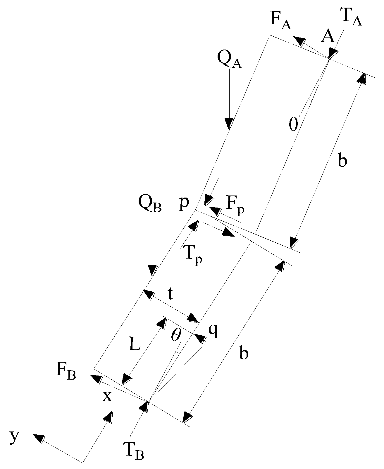
3.1. Mechanical Model of Overburden Fracture

The direct roof of the coal seam in the fifth mining area of Yaojie No. 3 mine is a composite rock layer of 2.3 m fine sandstone and coal. The thickness of the rock stratum is thin, and the filling degree of the caving rock stratum of the goaf is low. After segmented coal seam mining, the main roof will form an upturned “suspended roof” structure, as shown in Figure 2. Due to the high concentrated stress acting on the lower fulcrum of the structure, the roof roadway ground pressure appears. When the length of the structure exceeds its limit, the old roof breaks and turns, releasing a large amount of energy. The large amount of energy release in a short time may lead to impact damage and strong ground pressure behavior.
The length of the “suspended roof” structure of the main roof fracture, bending and rotation is l , the load of the overlying strata is q , the roof bending is loaded, M is its moment, and α is its corner, then the energy generated by the roof deformation can be calculated as follows:
W = 1 2 M α
The calculation of the moment can be expressed as the moment of the load against the fulcrum, which can be expressed as follows:
M = 1 2 q cos β l 2
According to the mechanics of materials, the second-order differential equation of deflection can be expressed as follows:
d 2 v d x = M E I
where E I is the bending stiffness of the section.
It can be observed from Figure 2 that the bending moment equation can be obtained by taking the distance of any section of the “suspended roof” structure as follows:
M = q cos β l x l x / 2 = q cos β ( l x ) 2 / 2
One can substitute M, integrate α and combine the boundary conditions to obtain
W = 1 2 M α = ( q cos β ) 2 l 5 24 E I

3.2. Hinged Rock Beam Structure after Broken Overburden

When the strength of the immediate roof is low and the thickness of the immediate roof is large or in the area where the coal seam becomes thin and the inclination becomes large, the caving coal and rock mass accumulates at the bottom of the goaf beside the roof under the influence of mining, which easily meets the conditions of forming a “masonry beam” structure. The main roof is broken, and the lower part is a relatively dense filling body, and the upper filling body is very loose or suspended. Because the dip angle of the coal seam in Yaojie No. 3 Mine is greater than 45°, the broken rock plate easily forms a more stable structure along the dip direction under the action of the component force along the dip, that is, the “hinged rock plate” structure. Through the tensile stress analysis of the roof, when the rock plate does not reach its tensile strength σ S , after the foundation coefficient K > 2, with the increase in K, the difference between the maximum tensile stress of the upper surface of the rock plate at the midpoint of the upper and lower end boundaries and the stress at other points on the boundary gradually decreases, that is, most of the load of the one-way rock plate is carried by the short-span (inclined) edge. At this time, the analysis of rock strata can be replaced by rock beams. Therefore, the “hinged rock slab” structure after the main roof is broken can be replaced by the “hinged rock beam”, and its mechanical model is shown in Figure 3.
One can suppose that the length of the upper and lower parts of the rock beam is B, the thickness is t, and the rotation angle is θ , the uniformly distributed load on the rock beam is Q A = Q B = Q , and the extrusion thrust and contact hinge friction shear at the three-hinge points A, P and B are T A , F A , T P , F P T B , F B , respectively. The gangue filled in the lower rock beam is regarded as an elastic foundation, the foundation coefficient is K, and the gangue filling length is l; therefore, the total foundation stress is as follows:
q = 1 2 k l 2 s i n θ
Take M A = 0 , M P = 0 , Y = 0 .
The extrusion thrust T and friction shear F at the three hinge points are as follows:
T A = 1 2 ( t b s i n θ ) b Q cos α 2 Q t b sin θ sin α k l 3 sin θ 3
T p = 1 2 ( t b s i n θ ) b Q cos α k l 3 sin θ 3
T B = 1 2 ( t b s i n θ ) b Q cos α + 2 Q t b sin θ sin α k l 3 sin θ 3
F p = Q t b s i n θ sin α 2 b 2 k l 3 sin θ 3 b
F A = Q c o s α + 3 Q t b sin θ sin α 2 b 2 k l 3 sin θ 3 b
F B = Q c o s α + Q t b sin θ sin α 2 b + 2 k l 3 3 b 2 k l 3 sin θ
From the analysis of Equations (6)–(11), the “hinged rock beam” structure has the following characteristics.
The extrusion thrust at point B is greater than that at point P, and the extrusion thrust at point P is greater than that at point A, while the frictional shear force at point A is greater than the one at point B, and the frictional shear force at point B is larger than the one at point P. The size of the extrusion thrust and friction shear is proportional to the load on the rock beam, that is to say, the deeper the mining is, the worse the stability of the structure is. The extrusion thrust and friction shear at the hinge point decrease with the increase in the dip angle of the rock stratum, so the larger the dip angle is, the easier it needs to be to establish a stable structure. The greater the length of rock slab (b value), the greater the extrusion thrust at the hinge point, and the smaller the friction shear. Therefore, the greater the segment height, the worse the stability of the structure. With the increase in the rotation angle, the extrusion thrust increases, the friction shear decreases, and the structural stability becomes worse. The longer the filling length of the rock beam at the lower part of the structure is, the larger the foundation coefficient is, and the easier it is to form a hinged stable structure.
Under the condition of horizontal sublevel top coal caving in steep seam, the “hinged rock beam” structure formed by the main roof is in a dynamic equilibrium state with the continuous instability and formation of a new stable structure in the mining process. Broken roof strata mainly show two forms of sliding and rotary instability.
(1)
Sliding instability
It can be observed from the analysis Equations (6)–(11) that the extrusion thrust at the hinge point A is the smallest and the friction shear force is the largest, so the sliding instability is most likely to occur at A. The conditions to prevent slippage instability are as follows:
T A t a n φ F A  
where tan φ is the friction factor at hinge point A .
(2)
Slewing instability
When the hinged structure is in a balanced state, the main influencing factors leading to the rotation instability are as follows: the plastic failure caused by the excessive extrusion thrust at the lower hinge point leads to the rotation instability of the structure; the elastic filling body at the lower part of the rock beam continues to slide downward, causing structural instability.
The hinge point A plays a key role in the stability of the whole “hinge” structure. When the structure formed by the broken roof strata is unstable, it will cause strong dynamic load disturbance to the working face. If the immediate roof is thin, the filling degree of the goaf formed by the broken coal and rock mass is relatively low and the impact of the dynamic load on the working face will be very strong, so the impact resistance of the hydraulic support should be considered, and the support with larger working resistance should be selected; when the immediate roof is thick, the crushed coal and rock mass form a buffer zone, which plays the role of buffer protection for the working face.

3.3. Space-Time Evolution Law of Overburden Structure Breakage and Instability

Based on the occurrence of overburden in the Yaojie No. 3 mine and the above law of overburden breakage and instability, the spatio-temporal evolution diagram of overburden breakage and instability is drawn, as shown in Figure 4.
It can be observed from the figure that when the working face is not mined, the topsoil structure is above the coal seam, and the roof is intact and not broken, as shown in Figure 4a. After the working face is mined, with the top coal being released, the topsoil structure above the coal seam also falls down and continues to attach to the top coal of the lower layer. Due to its thin thickness and small breaking distance, the immediate roof gradually falls down with the mining of the working face, forming a loose structure. When the mining range in the dip direction is large enough to reach the breaking distance of the main roof, the main roof breaks, and sinks, but the broken rock blocks of the main roof are relatively stable and overlap on the structure formed by the broken direct roof. With the mining and top coal caving of the working face, the gangue in the goaf and the remaining coal that has not completely caved move downward. The immediate roof block and the main roof block will also continue to sink and rotate to the depth, gradually parallel to the floor, and the main roof block will form a more stable hinge structure after breaking several times; on the one hand, it will bear the weight of the easily broken roof above the main roof and on the other hand, it will act on the gangue in the goaf and transfer part of the weight to the top coal and working face. With the further increase in the mining space, the span of the roof will gradually increase, and the sub-key layer 2 will also break and sink, and move together with the broken roof of the lower layer to form a lap structure, as shown in Figure 4b.
The sub-key stratum 1 and sub-key stratum 2 are broken periodically as the working face continues to mine downward. With the continuous movement of the working face, when the mining area continues to expand and reaches the breaking distance of the main key stratum, the main fundamental stratum will bend and sink until it is broken. After breaking, it will rotate and sink, and overlap on the structure formed after the breaking of the lower horizon. In the breaking and sinking of the main key stratum, it will cause the rock strata up to the surface to sink, forming a sinking area. According to the breaking, hinging and migration laws of the above overburden strata, the breaking and migration states of the overburden strata can be roughly drawn when the 10th, 15th and 20th layers are mined, as shown in Figure 4c–e.

3.4. Development and Failure Law of Overburden Fissures

As shown in Figure 5, from the analysis of the change law of rock fracture development, with the progress of layered mining, the fractures continue to expand to the high hard key stratum, the overlying strata are separated one after another, and at the same time, the fractures in the coal body expand to the depth of the coal seam, and a fracture zone appears near the floor in the lower coal body, where the weak surface of the coal body is abundant and the strength is weak.
As shown in Figure 6, tension and sliding failure mainly occurred in the coal body, and the sliding failure in the coal body is more than the tension failure, forming a shear failure zone near the side of the bottom plate.

4. The Mechanism of Dynamic and Static Loads Superimposed on Induced Scour in Horizontal Sublevel Mining of Steep and Extra-Thick Coal Seams

4.1. Static Load Condition

The static load stress in the mining process of the working face is mainly composed of the original rock stress and mining supporting pressure. The original rock stress mainly refers to the self-weight stress and structural stress. The self-weight stress depends on the mining depth, and the structural stress, such as faults, makes the stress distribution abnormal.
The original rock stress is expressed as follows:
σ j 1 = γ H = 1 + λ γ H
where λ is the tectonic stress coefficient.
After the mining activities are carried out in the coal and rock mass, the part where the stress of the surrounding coal and rock mass increases due to the load transfer of the overlying strata in the goaf space is called the mining support stress, which can be expressed by the following equation:
σ j 2 = k 1 γ H
Then, the total static load of surrounding rock system can be expressed as follows:
σ j = σ j 1 + σ j 2 = k + λ γ H
(1)
Self-weight stress field. The average mining depth of the three mines is 480–510 m, which provides the critical depth of impact.
(2)
Tectonic stress field. Tectonic stress mainly refers to the tectonic stress near the fold and the tectonic stress near the fault. The steep occurrence of the Yaojie No. 3 mine determines that it must be affected by a wide range of geological structures. In addition, the fault F607 near the working face of the fifth mining area is in the pinch out area, and the fault drop is 50–150 m, and the structural stress is concentrated. In addition, the fifth mining area is also affected by a fault cutting, such as the fault F15 near the cutting hole, with a drop of 150 m, and F604. Table 2 provides details of the geological structure characteristics near the working face.
(3)
Stress concentration in mining space.
It can be observed from the overburden structure diagram that the sub key layer near the roof side of the working face easily forms a suspended roof, resulting in the air inlet roadway and the end of the working face in the stress concentration area. In addition, the air intake roadway is staggered and overlies the goaf by 10–15 m, which also belongs to the stress concentration area. Due to the stoping of the working face, the roof and floor have a tendency to swing towards the goaf, producing shear forces in the opposite direction, making the floor of the working face a strong shear zone and prone to shear failure.
Figure 7 shows the maximum shear stress diagram (Figure 7a) and plastic zone distribution (Figure 7b) on the inclined section obtained by FLAC3D numerical simulation. It can be confirmed from Figure 8 that the shear stress at the bottom plate of the working face is concentrated, and the area close to the side of the return air roadway is in a plastic state.
The coal body of the working face is clamped in the middle of the roof and floor. Affected by mining, the stress distribution on the roof and floor side is uneven after the stress of the working face is redistributed, and the stress concentration on the roof side is high. The working face is mined in layers from top to bottom, and the vertical stress is released, but it is still subject to large horizontal stress. Therefore, mining support stress has the greatest impact on the static load condition, so the bottom coal is in a state of high stress concentration and becomes the static load force source-inducing impact.

4.2. Dynamic Load Conditions

In the process of mining, the coal and rock mass around the mining space produces stress concentration and elastic energy accumulation. When stress or elastic energy exceeds its bearing limit value, the coal and rock mass breaks, and the accumulated elastic energy propagates to the surrounding space in the form of vibration stress wave, forming a mine earthquake. It mainly includes mining earthquakes caused by roof pressure, coal pillar damage, roof fracture, large-scale movement of overlying strata, fault slip, etc.
After the vibration caused by the erosion rock breaking, it will propagate outward in the form of the stress wave. When the seismic wave propagates to the surrounding rock, the peak dynamic load σ d imposed by the seismic disturbance can be expressed as follows:
σ d p = ρ v p ( v p p ) p σ d s = ρ v s ( v p p ) s
where σ d P and σ d S are the dynamic loads of the P wave and S wave in turn; ρ is the density of coal rock medium; v P and v S is the propagation velocity of the P wave and S wave in turn, ( v p p ) P and ( v p p ) S are the peak vibration velocity of the P wave and S wave in turn, which is generally positively correlated with the vibration energy. Its dynamic load mainly includes the following three aspects:
(1)
Dynamic load is induced by the failure and instability of overburden structures
When the roof overburden can form an articulated bearing structure (Figure 8a), the working face support only bears the load of the top coal and direct roof. With the expansion of the mining space, the overburden will no longer form an articulated bearing structure. At this time, the source of dynamic load consists of the following two aspects: (1) overburden breaking and rotation; (2) the “hinged structure” formed by overburden, which is unstable. Failure and instability of roof overburden structures are the main sources of dynamic loads.
(2)
Fault slip induced dynamic load
As shown in Figure 9, the Fx fault in the fifth mining area is inclined to the working face, which is a normal fault with a strike of N40° E, dip of NW, dip angle of 70–75°, and drop of 5–20 m. The mining disturbance leads to the overall movement of the fault footwall, which induces large energy mine earthquakes and impacts the support of the working face.
(3)
Dynamic load induced by floor and coal fracture
In the mining process of the working face, it is not only the roof overburden that will be broken and unstable, but also the floor rock near the excavation disturbance and the coal body of the working face will also be broken and form a dynamic load, which has been verified by the on-site microcosmic monitoring results. Because the dynamic load produced by the floor and coal body is close to the working face, the near-field mine earthquake will be more likely to induce impact behavior.

4.3. Mechanism of Dynamic and Static Load Superposition Induced Impact

The excavation of the working face or mining roadway causes the redistribution of the stress of the surrounding coal and rock mass. In the process of the stress of rebalancing of the surrounding rock in the mining space, the surrounding rock will form local stress concentration due to elastic deformation, and some of the surrounding rock will be damaged to a certain extent due to the stress concentration. If the surrounding rock structure is not completely destroyed, at this time, the additional supporting structure can still maintain its stability. Otherwise, when the superimposed static load stress field formed by the surrounding rock structure under the action of the original rock stress and mining stress is higher than the ultimate bearing strength of the surrounding rock mass of the roadway, it will cause the impact damage of the stope or roadway. Generally, under the action of the support system, only the static load of the stope and roadway is less likely to cause impact damage to the coal rock system.
When the static load of stope or roadway is stable, the shock dynamic load σ d transmitted by the vibration effect of the fracture of the external coal and rock mass is superimposed with its original static load σ j , so that the stress intensity of the surrounding rock is higher than the ultimate strength σ b m i n of the surrounding rock mass of the roadway, the balance of the surrounding rock mass is broken, and the mining roadway will be destroyed instantaneously, or the impact failure will occur through repeated tension and extrusion of the shock dynamic load stress wave, resulting in shock appearance. According to the energy criterion of rockbursts, it can expressed as follows:
d U R d t + d U C d t + d U S d t > d U B d t
where UR, UC, and US are the energy stored in the surrounding rock and coal body, and UB is the energy consumed when a rockburst occurs.
The left side of the inequality can be expressed by Equations (18) and (19).
U = σ j + σ d 2 E 2
U b m i n = σ 2 b m i n 2 E
where σ j and σ d are the static loads in coal and rock mass and the dynamic load formed by mine earthquakes, respectively, and σ b m i n is the minimum load when a rock burst occurs.
According to Equations (18) and (19), the critical condition for the occurrence of rock burst is as follows:
σ s + σ d σ b m i n
According to Equation (20), the mechanism of rockbursts induced by dynamic and static load superposition is that the superposition of the static load in coal and rock mass and dynamic load formed by mine earthquakes is greater than the minimum load of impact.
Due to the particularity of the geology and mining conditions of steep coal seams, the fault structure is developed, and the mining work causes the coal body of the working face to be a part of a high static load area. Under the action of the surrounding mining dynamic disturbance, the roof fracture and instability, the floor and coal body fracture, and the fault slip will form a mine earthquake to exert the dynamic load on the working face. The superposition of the originally high static load and dynamic load stress exceeds the ultimate strength of the coal and rock mass. At the same time, the elastic energy accumulated in the coal and rock mass and the vibration energy released and transmitted by the mine earthquake are superimposed, which leads to instability and failure of the coal and rock mass system and large-scale impact dynamic disasters.

5. Discussion

Numerous scholars have carried out extensive research on the overburden fracture migration characteristics and impact mechanisms in mining steeply inclined coal seams. Wu Yongping et al. [34] constructed a sloping masonry structure of roof breakage in the mining of steeply inclined coal seams, and pointed out that the unbalanced migration of this structure was the leading inducement of stope support instability and failure. Shi Pingwu [35] constructed the overburden “cross-layer arch” structure for mining steeply inclined coal seams, and analyzed the influence rule of sliding instability and deformation instability of the structure on the mine pressure appearance. Ju Wenjun et al. [16,17] constructed the fracture mechanical model of inclined cantilever beams in steeply inclined sublevel mining of the old roof strata, and deduced the elastic energy expression of inclined cantilever beams in old roof strata. Lai Xingping et al. [18,19,20,21] built a roof stress model for mining steeply inclined coal seams based on beam theory and revealed its deformation law, and carried out a laboratory test, relying on the plane combined loading test device to reveal the evolution characteristics of temperature and acoustic emission during the fracture process of steeply inclined rock pillars under the influence of mining. The main research object of the existing dynamic disaster of steeply inclined coal rock is the roadway impact, and there are few studies on the stope impact of steeply inclined sublevel mining. The influence mechanisms of the working face and roadway are both related and different under the stress state of the coal body in the stope. The existing steep dynamic disaster research focuses on the strata structure fracture instability on the impact of the dynamic load, and the shock that occurs in mining coal. It also only focuses on the characteristics of the stress of the small structures of roadway surrounding rock the whole stope. Research on the stress of coal and rock mass structures has not yet fully revealed the steep thick coal seam sublevel impact mechanism. On the basis of previous studies, this paper takes the mining of 5521 working faces of steeply inclined extra-thick coal seams in the Yaojie No. 3 mine as the background, and studies the overburden structure fracture, spatio-temporal evolution law and induced shock mechanism in horizontal subsection mining of steeply inclined extra-thick coal seams. This paper reveals the characteristics of overburden migration and ore pressure in the incline section of sharply inclined sublevel mining stopes, and fails to consider the overburden fracture and instability along the advancing direction of the working face and the evolution law of the mining stress field, which deviates from the reality. Therefore, it is necessary to use the 3D discrete element 3DEC numerical simulation software to study the mining of steeply inclined coal seams under the state of three-way forces. This paper has carried on the mechanism research, but lacks quantitative research. Next, it needs to combine the highest control factors to carry on the quantitative research on the force division of the clamping coal body, to better guide the on-site production. Further study should include the impact of key strata azimuth and thickness on impact generation and strength, especially for the near vertical coal seam and it is necessary to also consider the impact of the roof and floor, and the failure characteristics of coal and rock in the stope.

6. Conclusions

(1)
With the increase in mining depth, the roof is transformed from the original stress arch structure to the hinged rock beam structure. In the mining process, double and multiple arch structures are formed, which have a definite bearing capacity. The instability of the large arch structure above will have an important impact on the stability of the lesser arch structure, and bring impact risk to the working face at the same time. The dynamic load formed by the instability of the key layer arch structure is the leading factor of rock-bursts in stratified mining of steep coal seams.
(2)
The asymmetry of the roof and floor makes the end of the coal body that is close to the air intake roadway in the working face a strong shear stress zone, which accumulates elastic properties, is prone to shear failure and has poor stability. Lateral support pressure and coal shear stress in the goaf are the static load sources of rock-bursts in steep coal seams.
(3)
After the roof overburden of the steeply inclined coal seam is broken, an articulated bearing structure is easily formed under the support of the sliding force of the fault block and the floating gangue in the goaf. When mining and drawing coal in the lower section, it is not difficult to form a suspended structure under the bearing structure. When the roof breaks periodically or the structure rotates and slides unsteadily, the strong dynamic load formed by the influence of the fault block on the top coal is the main dynamic load source of the impact of the working face. In addition, local fault activity or brittle failure of the intense shear zone of bottom coal can also form a strong dynamic load.
(4)
With the progress of layered mining, the cracks continue to expand to the high-level hard key layer, and there is a crack zone near the floor in the lower coal body, with weak strength. The slip failure in the coal body is greater than the tension failure, and a shear failure zone is formed on the side near the floor. This damage is formed in the mining process of the working face. When driving the lower stratified return air roadway, it is in the plastic zone, with low stress concentration and low impact risk.
(5)
The superposition stress of the dynamic load and static load reaches the state of large-scale instability and failure of the coal and rock, inducing the destruction of the coal body to release energy. For steep extra-thick coal seams, the shear failure of bottom coal in the working face releases energy, and the dynamic and static superposition rock-bursts occur when the energy released during the destruction of the coal and rock system is more important than the energy consumed.

Author Contributions

Writing—original draft, S.G. and B.Z.; Writing—review and editing, B.Z. and Q.C.; Supervision, C.Y. and Y.W.; Software, S.G. and B.Z.; Conceptualization, B.Z. and Q.C.; Administration, Q.C.; Validation, Investigation, C.Y.; Methodology, S.G.; Resources, Y.W. All authors have read and agreed to the published version of the manuscript.

Funding

This research was supported by the projects of “National Natural Science Foundation of China (52174130)”; “National Natural Science Foundation of China (52074270)”.

Institutional Review Board Statement

Not applicable.

Informed Consent Statement

Not applicable.

Data Availability Statement

The Microsoft Excel Worksheet data used to support the findings of this study are available from the corresponding author upon request.

Conflicts of Interest

The authors declare no conflict of interest.

References

  1. Gao, M.Z.; Yu, Z.L. Repetitive mining subsidence with thick soil layers and steep seam. J. China Coal Soc. 2007, 32, 347–352. [Google Scholar]
  2. Jiang, F.; Wang, P.; Feng, Z. Mechanism, prediction and control of “rock burst by shock “dynamic disaster in compound thick coal seam. J. China Coal Soc. 2009, 34, 1605–1609. [Google Scholar]
  3. He, M.; Xie, H.; Peng, S.; Jiang, Y.-D. Study on rock mechanics in deep mining engineering. Chin. J. Rock Mech. Eng. 2005, 24, 2803–2813. [Google Scholar]
  4. Jiang, Y.D.; Pan, Y.S.; Jiang, F.X.; Dou, L.M.; Ju, Y. State of the art review on mechanism and prevention of coal bumps in China. J. China Coal Soc. 2014, 39, 205–213. [Google Scholar]
  5. Dai, H.Y.; Guo, J.T.; Yi, S.H.; Wang, G.Y.; Liu, A.J. The mechanism of strata and surface movements induced by extra–thick steeply inclined coal seam applied horizontal slice mining. J. China Coal Soc. 2013, 38, 1109–1115. [Google Scholar]
  6. Sainoki, A.; Mitri, H.S.; Yao, M.; Chinnasane, D. Discontinuous modelling approach for stress analysis at a seismic source: Case study. Rock Mech. Rock Eng. 2016, 49, 4749–4765. [Google Scholar] [CrossRef]
  7. Dou, L.; He, X. Technique of classification forecasting rock burst in coal mines. J. China Univ. Min. Technol. 2007, 36, 717–722. [Google Scholar]
  8. Wang, N.B.; Cao, J.T.; Lai, X.P. Characteristics of stope migration and roadway surrounding rock fracture for fully mechanized top coal caving face in steeply dipping and extra thick coal seam. J. China Coal Soc. 2013, 38, 1312–1318. [Google Scholar]
  9. Kang, X.; Yang, S.L.; Zhan, P.; Li, L.H. Simulation Study of the Roof Fracture Pattern of a Horizontal Sublevel Caving in a Steeply Inclined Thick Coal Seam. Adv. Civ. Eng. 2020, 2020, 8370634. [Google Scholar] [CrossRef]
  10. Yang, Y.; Wei, J.; Wang, C. Research on the Influence of Mining Height on the Movement Characteristics of Overlying Strata during Extremely Thick Coal Seam Fully Mechanized Sublevel Caving Mining. Adv. Civ. Eng. 2021, 2021, 6661581. [Google Scholar] [CrossRef]
  11. Sun, C.; Chen, D.; Chen, Y.; Lu, J. Study on collapse law and control of hard roof in steeply inclined coal seam. J. Rock Mech. Eng. 2019, 38, 1647–1658. [Google Scholar]
  12. Zhang, Y.; Zhang, Z. Research progress on overburden failure law and control technology of coal mining. Coal Sci. Technol. 2020, 48, 85–97. [Google Scholar]
  13. He, C.; Lu, W.; Zha, W.; Wang, F. A geomechanical method for predicting the height of a water–flowing fractured zone in a layered overburden of longwall coal mining. Int. J. Rock Mech. Min. Sci. 2021, 143, 104798. [Google Scholar] [CrossRef]
  14. Zhu, Z.; Guan, S. Prediction of the Height of Fractured Water–Conducting Zone Based on the Improved Cuckoo Search Algorithm–Extreme Learning Machine Model. Front. Earth Sci. 2022, 10, 494. [Google Scholar] [CrossRef]
  15. Jiang, F.X.; Shi, X.F.; Wang, C.W.; Wei, Q.D. Mechanical mechanism of rock burst accidents in slice mining face under high pressure. Chin. J. Geotech. Eng. 2015, 37, 1123–1131. [Google Scholar]
  16. Ju, W.J.; Zheng, J.W.; Wei, D.; Sun, L.W.; Li, W.Z. Study on the causes and control technology about the coal bump in multi–layered mining roadway in steep–thick coal seams. J. Min. Saf. Eng. 2019, 36, 280–289. [Google Scholar]
  17. Ju, W.; Li, W. Fracture mechanical model of main roof along inclined for fully mechanized top coal caving in steep and extra thick coal seam. J. China Coal Soc. 2008, 33, 606–608. [Google Scholar]
  18. Lai, X.; Liu, B.; Chen, J. Induced hazardprone prediction to the intermediate rock–pillar dynamic instability in heavy steep–thick coal seam. J. Xi’an Univ. Sci. Technol. 2015, 35, 277–283. [Google Scholar]
  19. Lai, X.; Sun, H.; Cai, M. Mechanism of dynamic hazards due to coal and rock mass instability in extremely steep coal seams with the deepening mining. J. Xi’an Univ. Sci. Technol. 2017, 37, 305–311. [Google Scholar]
  20. Lai, X.; Yang, Y.; Chen, J.Q.; Ge, R.Z.; Cui, F.; Shan, P.F. Control of dynamic hazards induced by mining stress distortion in extremely steep and thick coal seams. J. China Coal Soc. 2016, 41, 1610. [Google Scholar]
  21. Lai, X.; Yang, Y.; Shan, P. Comprehensive analysis of disaster–causing characteristics of roof stress superimposed effect in steeply inclined coal seams. J. China Coal Soc. 2018, 43, 70–78. [Google Scholar]
  22. Wang, Z. Study on the Mechanism of Clamped Impact Instability in Horizontal Sublevel Mining of Steep Extra Thick Coal Seams; China University of Mining and Technology: Xuzhou, China, 2019. [Google Scholar]
  23. Wang, Z.; Dou, L.; Wang, G. Coal burst induced by horizontal section mining of a steeply inclined, extra –thick coal seam and its prevention: A case study from Yao jie No.3 Coal Mine, China. Shock. Vib. 2019, 2019, 1–13. [Google Scholar] [CrossRef]
  24. Li, A.; Dou, L.; Wang, Z.; Xie, J.; Wang, Y. Rock-burst mechanism and prevention of clamping coal in miningnear-vertical coal seam with horizontal slice method. J. China Coal Soc. 2018, 43, 3302–3308. [Google Scholar] [CrossRef]
  25. Dou, L.; He, J.; Cao, A.; Gong, S.; Cai, W. Superposition principle of dynamic and static loads of rockburst in coal mine and its prevention. J. Coal Ind. 2015, 40, 1469. [Google Scholar]
  26. Zhang, B.; Zhou, H.; Chang, Q.; Zhao, X.; Sun, Y. The Stability Analysis of Roadway near Faults under Complex High Stress. Adv. Civ. Eng. 2020, 2020, 8893842. [Google Scholar] [CrossRef]
  27. Chen, J.; Zeng, B.; Liu, L.; Tao, K.; Zhao, H.; Zhang, C.; Zhang, J.; Li, D. Investigating the anchorage performance of full–grouted anchor bolts with a modified numerical simulation method. Eng. Fail. Anal. 2022, 141, 106640. [Google Scholar] [CrossRef]
  28. Chen, J.; Liu, P.; Liu, L.; Zeng, B.; Zhao, H.; Zhang, C.; Zhang, J.; Li, D. Anchorage performance of a modified cable anchor subjected to different joint opening conditions. Constr. Build. Mater. 2022, 336, 127558. [Google Scholar] [CrossRef]
  29. Du, T.; Chen, J.; Lan, H.; Sun, B.; Yang, L.; Liu, X. Analysis on mine pressure bump of near vertical ultra thick seam with upper layer mining and lower layer excavation. Coal Sci. Technol. 2016, 44, 123–127. [Google Scholar]
  30. Yu, G.; Li, Q.; Wang, Y. Prevention and control technology of rock burst in layered mining of deep steep and extra thick coal seam. Coal Sci. Technol. 2011, 39, 17–21. [Google Scholar]
  31. Lu, W.B.; Wu, Y.M.; Chen, J.; Fu, H.L. Safety Analysis of Tunnel in Gob of High Steep Thick Coal Seam (II)—3–D Numerical Simulation for Mechanics of Initial and Secondary Support Structure. Appl. Mech. Mater. 2011, 1366, 1539–1545. [Google Scholar] [CrossRef]
  32. Zhang, J.F.; Liu, X.; Liu, Y.; Shao, X.P.; Zhang, H.M. Study of Top Coal Partition and Key Delayed–Action Region for Horizontal Sublevel Top Coal Caving in Deeply Inclined Seam. Math. Probl. Eng. 2021, 2021. [Google Scholar] [CrossRef]
  33. Yun, D.; Liu, Z.; Cheng, W.; Fan, Z.; Wang, D.; Zhang, Y. Monitoring strata behavior due to multi–slicing top coal caving longwall mining in steeply dipping extra thick coal seam. Int. J. Min. Sci. Technol. 2016, 27, 179–184. [Google Scholar] [CrossRef]
  34. Xie, P.S.; Wu, Y.B.; Ren, S.A.; Yu, H.W. Incline masonry structure around the coal face of steeply dipping seam mining. J. China Coal Soc. 2010, 35, 1252–1256. [Google Scholar]
  35. Shi, P.W.; Zhang, Y.Z. Structural analysis of arch of spanning strata of top coal caving in steep seam. Chin. J. Rock Mech. Eng. 2006, 1, 79–82. [Google Scholar]
Figure 1. Depiction of 5521-21 working face roadway layout profile.
Sustainability 14 11980 g001
Figure 2. Calculation model of main roof fracture.
Sustainability 14 11980 g002
Figure 3. Mechanical model of “hinged rock beam”.
Sustainability 14 11980 g003
Figure 4. Schematic diagram of overburden structure evolution. (a) Structural drawing of overburden when not mined; (b) structural drawing of overlying strata of mining 5 layers; (c) structural drawing of overlying strata of mining 10 layers; (d) structural drawing of overlying strata of mining 15 layers; (e) structural drawing of overlying strata of mining 20 layers.
Sustainability 14 11980 g004
Figure 5. Fracture development of rock stratum. (a) Excavation 032 (red); (b) excavation 045 layers (red).
Sustainability 14 11980 g005
Figure 6. Tension and shear diagram of coal body.
Sustainability 14 11980 g006
Figure 7. FLAC3D numerical simulation results. (a) Maximum shear stress diagram; (b) distribution of plastic zone.
Sustainability 14 11980 g007
Figure 8. Process of roof overburden structure breaking and instability. (a) Before breaking; (b) After breaking.
Sustainability 14 11980 g008
Figure 9. Fault slip induced thrust.
Sustainability 14 11980 g009
Table 1. Situation of coal seam roof and floor.
Stratum NameLithologyThickness (m)Lithology Description
Old roofFour layers of oil8It is black, with a dense structure and developed bedding.
Direct roofQuartz fine sandstone2~3Gray, off-white, siliceous cementation, dense and hard.
False roofCarbonaceous mudstone1~1.6Black, scaly structure, easy to slide and fall.
Coal SeamThe second layer of coal34~115Black, banded structure.
Direct floorCarbonaceous mudstone intercalated with coal streak or carbonaceous siltstone2~6Grayish-black carbonaceous mudstone and sandstone are interbedded, broken and with developed fissures.
Old floorSandstone0~232.61Fine greyish-white sandstone.
Table 2. Geological structure features near working face.
Structure NameStructure NatureTrendTendencyDip AngleFalling Head (m)
F15Normal fault110°NE75°50~130
F604Reverse faultN46° WNE80°80~260
F607Reverse faultN85° ENW50°10~20
Publisher’s Note: MDPI stays neutral with regard to jurisdictional claims in published maps and institutional affiliations.

