Article

Design Concept for a Greened Timber Truss Bridge in City Area

1
Institute of Structural Engineering, University of Natural Resources and Life Sciences, Vienna, Peter-Jordan-Straße 82, 1190 Vienna, Austria
2
designkollektiv GmbH, Rochusgasse 6/1, 1030 Wien, Austria
3
Institute of Soil Bioengineering and Landscape Construction, Peter-Jordanstraße 82/III, 1190 Vienna, Austria
4
HTBLA Hallstatt, Abteilung für Holz- und Restauriertechnik, Lahnstraße 69, 4830 Hallstatt, Austria
*
Author to whom correspondence should be addressed.
Sustainability 2020, 12(8), 3218; https://doi.org/10.3390/su12083218
Submission received: 2 March 2020 / Revised: 31 March 2020 / Accepted: 7 April 2020 / Published: 16 April 2020
(This article belongs to the Special Issue Advanced Construction and Architecture 2020)

Abstract

:
Properly designed wooden truss bridges are environmentally compatible construction systems. The sharp decline in the erection of such structures in the past decades can be led back to the great effort needed for design and production. Digital parametric design and automated prefabrication approaches allow for a substantial improvement of the efficiency of design and manufacturing processes. Thus, if combined with a constructive wood protection following traditional building techniques, highly efficient sustainable structures are the result. The present paper describes the conceptual design for a wooden truss bridge drawn up for the overpass of a two-lane street crossing the university campus of one of Vienna’s main universities. The concept includes the greening of the structure as a shading design element. After an introduction, two Austrian traditional wooden bridges representing a good and a bad example for constructive wood protection are presented, and a state of the art of the production of timber trusses and greening building structures is given as well. The third part consists of the explanation of the boundary conditions for the project. Subsequently, in the fourth part, the conceptual design, including the design concept, the digital parametric design, the optimization, and the automated prefabrication concept, as well as the potential greening concept are discussed, followed by a summary and outlook on future research.

1. Introduction

Material and energy lavishness in building constructions are shaping our current society. Economic efficiency still outranks environmental and social compatible design and construction. A good example of this phenomenon is the timber truss, a highly efficient solution of a linear load-bearing structure, which allows for optimal utilization of the construction material. Nevertheless, mainly plate girders made from glue laminated timber are used because of the easier and more economic production process. The disadvantage of plate girders, with their much lower efficiency regarding material utilization—especially for high loads and large spans, as is the case for bridges—is quickly overlooked for their economic efficiency. The continuous increase in the world population [1] goes hand in hand with the increase in demand for wood in different sectors [2], making the basic requirement of efficient use of the natural resources inevitable. In order to manage the increase of the global wood demand in a sustainable way, the following six possible approaches were defined in the WWF (World Wide Fund For Nature) living forest report 2012 [3]: (1) new plantation in the right places, (2) expanding production in well-managed natural forests, (3) forest certifications, (4) reuse and recycling, (5) fairer distribution, and (6) technological advances. A very important missing approach that would complement the list is a (7) high service life of constructions. The past has shown that traditionally built structures with a suitable design and an appropriate constructive wood protection have had a service life of several hundred years.
Urban growth and settlement pressure [4] have brought a series of additional challenges, such as the massive increase of grey infrastructure and sealed surfaces, the irreversible loss of biodiversity, and the production of anthropogenic heat. As described in [5], cities have a leading role in climate change. The greening of the built environment thus has important potential for counteracting urban heat and avoiding heat islands, as plants and vegetation provide cooling through shading and transpiration [6,7] and contribute considerably to retention and rain water management [8,9,10,11]. Green infrastructure has further positive impact at wellbeing and human comfort [12,13,14] and influences city dwellers from a creative point of view.
In this paper, the concept for a greened timber truss pedestrian bridge serving as an overpass over a two-lane street in city area is presented. The main requirements for the design concept were set as the following:
  • Most efficient use of material through optimized structural design;
  • Efficient and economic production process;
  • Best possible functionality in use as bridge and communal area;
  • Good integration into the surroundings;
  • Greening the structure.
The focus of the presented concept is to use technological advances in combination with an intelligent and attractive design for a high service life and the best possible functionality and integration into the surrounding. After the introduction, the first part of Section 2 of the paper gives an overview of the traditional construction techniques for timber bridges as a sound basis for the bridge design. Two chosen examples, the Rosannabrücke situated in Tyrol (Austria) and the Gosauzwangbrücke situated in Upper Austria (Austria), are described in detail, with one being a good and one a bad example for the implementation of constructive wood protection, which is necessary for a high service life of these structures. In the second part of Section 2, an overview of the state of the art of the design and the production of timber truss systems is given. The third part of Section 2 focuses on the state of the art of greening building structures. Section 3 explains the boundary conditions given for the project. Furthermore, Section 4 deals with the conceptual design of the presented truss bridge and is split in the subsections design concept, digital design, optimization and automated construction concept, and greening concept. Finally, a summary and an outlook on future research are given.

2. State of the Art

2.1. Comparison of Two Traditional Wooden Bridges

Using two existing bridge constructions from the mid-18th century as examples, the influence of constructive wood protection on the durability of wooden bridge structures can be clearly demonstrated. The first example is the Rosannabrücke located in Tyrol/Austria. Unfortunately, no construction plans from the time of origin exist for the oldest, mostly still original, wooden bridge spanning the Rosanna in Strengen am Arlberg (Tyrol). However, the exemplary state of maintenance and preservation of the bridge allows for a proper analysis of the constructive details and the long-term effects of a constructive wood protection. In addition, damage patterns and their causes can be found in a carefully inventoried documentation, which was carried out as part of the renovation work in 2014 on behalf of the Federal Monuments Authority Austria. The second bridge example, the Gosauzwangbrücke, a significant structural emblem of the United Nations Educational, Scientific and Cultural Organization (UNESCO) World Heritage Site Hallstatt-Dachstein/Salzkammergut (Upper Austria), tells a completely different story. The original plans were preserved unlike the bridge itself, which did not manage to withstand the climatic influences due to structural defects. Through a comparison of the two bridges, looking at similarities and differences in the constructive approach, general applicable rules can be derived, which, when implemented, can ensure long-term existence of future wooden structures. Both structures are situated in the northern alps between 500–1000 m above sea level and show similar traditional wood connections such as mortise and tenon as well as step joints and dovetails.
The embedding of the supports into the subsoil causes permanent moisture exposure, while the structure lifted from the ground is exposed to changing weather conditions. A reasonable approach to react to the boundary conditions is a separation of pier and bridge superstructure not only in a structural way, by choosing appropriate designs for the elements, but in respect of material choice as well. Wood on stone, a principle that extends from the two historical examples, is showcased in this paper to the pedestrian bridge spanning the Peter-Jordan-Straße, whose wooden superstructure rests on ultra-high-performance concrete (UHPC) pillars.

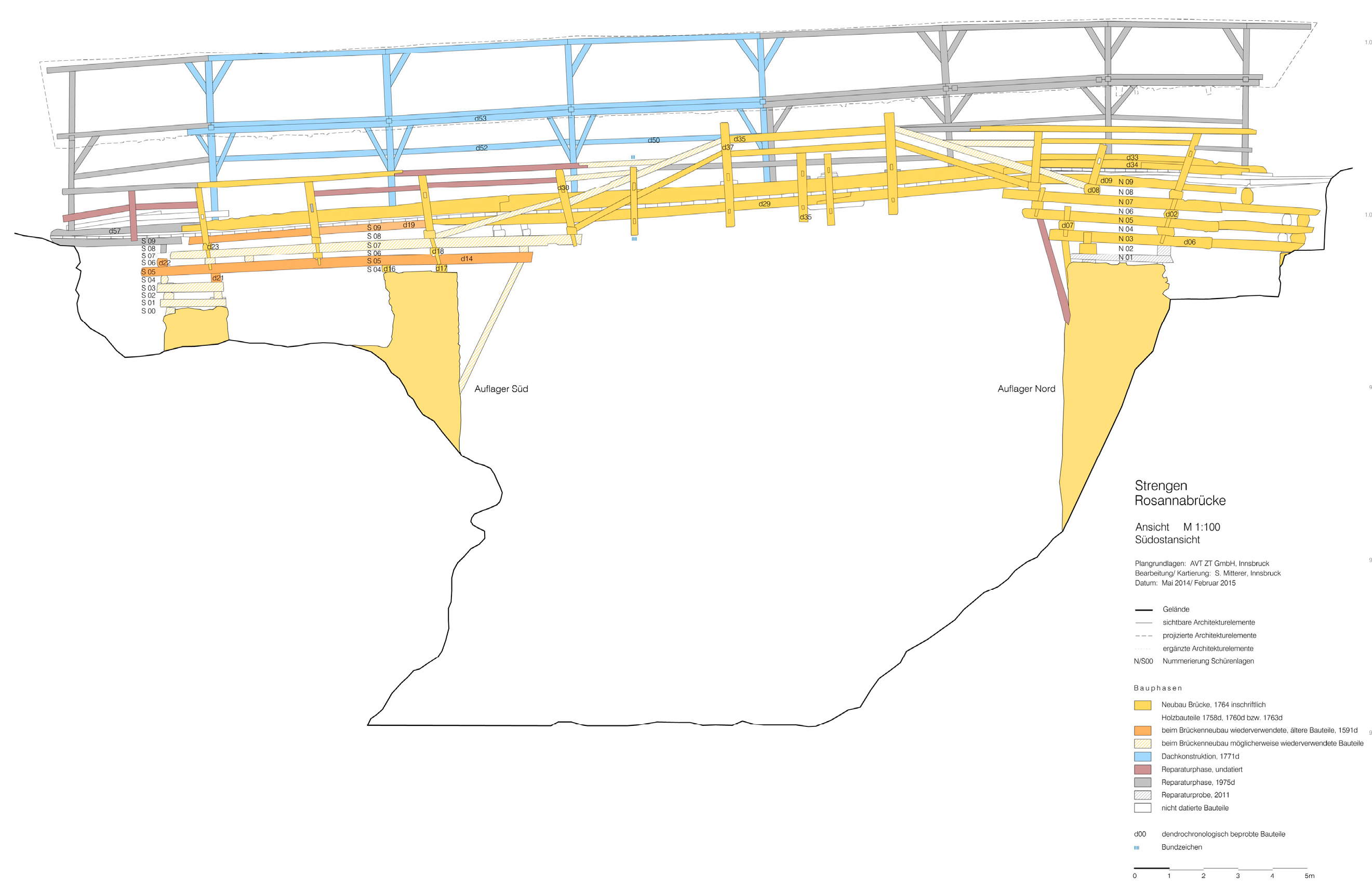
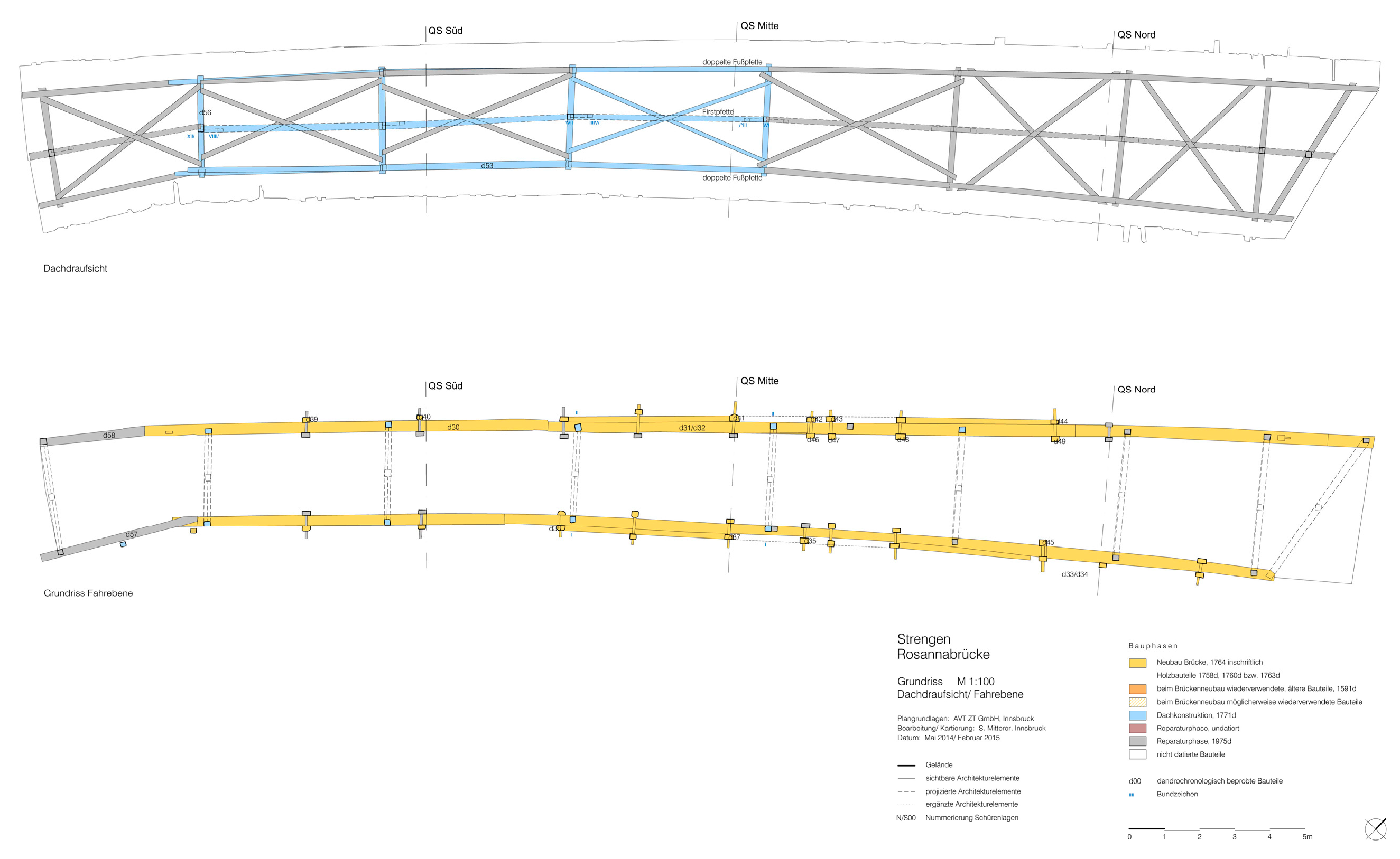
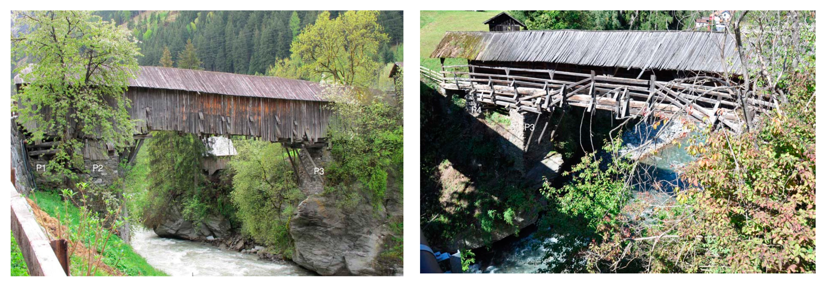
2.1.1. Rosannabrücke

In Strengen am Arlberg, at about 1000 m above sea level, the Rosanna is spanned by a wooden bridge called Rosannabrücke, which was built in 1764. The wooden superstructures of the bridge are based on tapered stone wall pillars and consist of a beam construction that is reinforced with a hanging structure. The bridge was protected using constructive measures against the climatic influences, resulting in the bridge being preserved in its original form. Figure 1, Figure 2 and Figure 3 show the documentation of the geometry of the bridge (front view, top view, and three cross sections) assessed in 2014/2015. Photographs of the bridge from inside, from below, and from both sides are displayed in Figure 4.
The construction, being the oldest wooden bridge in Austria, has a total length of approximately 40 m, with a free length of 18 m spanning the riverbed 15 m below. The load-bearing structure, which was built mainly of larch wood, consists of a combination of girder and compression only truss, which in turn rests on the superimposed beams projecting from the pillar heads [15]. The cantilever construction represents a relic of the original type of wooden bridge construction, in which the chasm was bridged by superimposed, ever-projecting beams [16]. With this design, the span of the central structure was reduced from 18 m to 13.5 m.
The main load-bearing structure is formed by two superimposed edge girders, which are strengthened by a queen post truss structure with double rafters and double collar beams. Split pins and wedges provide a connection of all members making iron nails or nuts dispensable. The slightly curved carriageway is covered with planks. This complex wooden structure mainly consists of horizontally arranged components, from which rain and melt water could not drain or evaporate fast enough. The high level of moisture of the horizontal surfaces, the mortises, and the wood substance underneath would lead to a high risk of fungal attack and the associated wood destruction.
To prevent the destruction due to moisture, the northwestern weather side is completely covered with vertical boards to protect the bridge surfaces against driving rain. Even in the detailed design, the elements are protected against the moisture with all grain surfaces covered with vertical “headboards” and all cantilevered components covered with inclined boards, allowing the rainwater to run off quickly.
The large structural protective surfaces defying the main directions of the weather attacks are wear elements that must be renewed periodically every 50 to 200 years. On the one hand, it is important to make the construction as simple as possible, so that craftsmen of later generations can easily deduct how the construction should be renewed. One the other hand, one should hope for the survival of the more subtle knowledge of the materials and the passing on of true craftmanship.
In the case of historical board coverings or vertical boarding, the so called “braid” or treetop-closer board ending should always point downwards. This mounting direction takes advantage of the wood-physiological fact that the movement of water in the cellular wood structure is smoothest in the tree’s growth direction, therefore allowing for a faster run down and drop of the moisture content after rainfall.

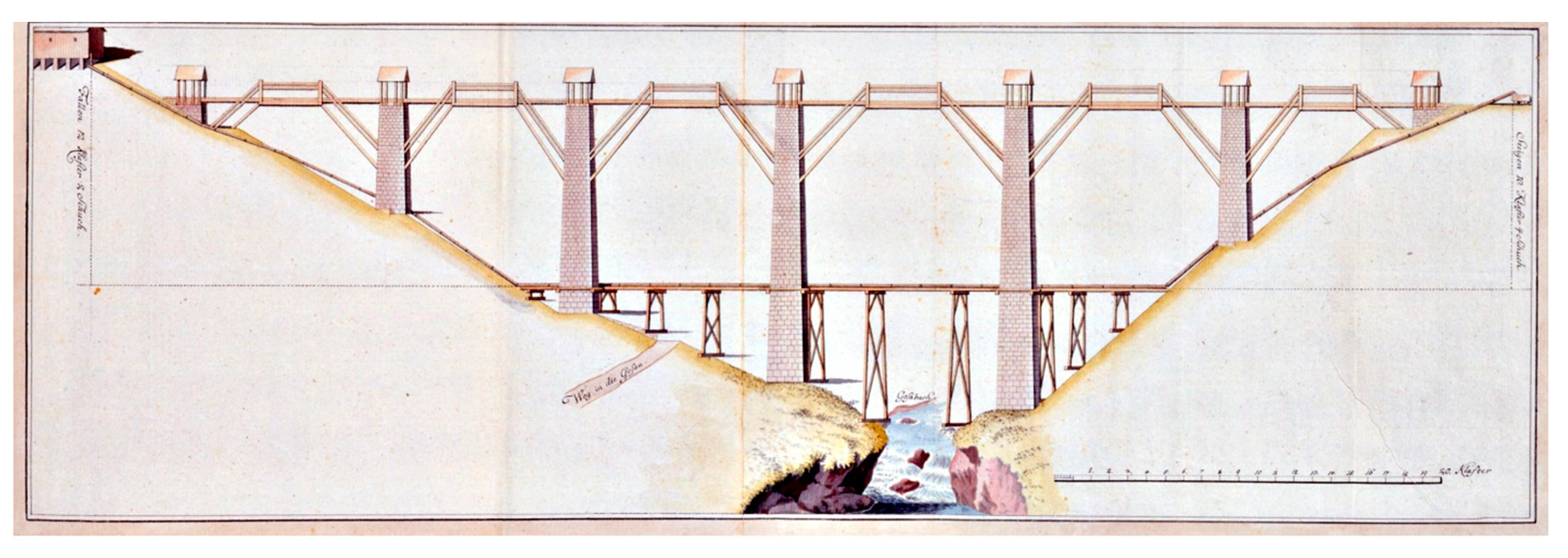
2.1.2. Gosauzwangbrücke

As with the Rosannabrücke, the Gosauzwangbrücke was built in the middle of the 18th century. The bridge represents an impressive solution for spanning a valley gorge, for the brine pipeline, the first modern raw material pipeline, was implemented in today’s UNESCO World Heritage region of Hallstatt-Dachstein/Salzkammergut (Upper Austria) [17]. The up to 37-m-high bridging of the Gosau creek, which is still used as a pipeline route, made it possible to lay the originally wooden pipeline with an even gradient, ensuring a steady line pressure [18].
Five stone pillars with heights between 10.4 m and 30.7 m and two bridgeheads are all that is left of the original 129 m long bridge once consisting of six bridge spans between 16 m and 21 m. The slim pillars, which taper 2 inches per fathom height (resulting in a gradient of 2.7%), have square cross sections and are made of massive limestone ashlar masonry, with the stones placed at the pillar crowns impressing with their dimensions of 0.7 m by 0.8 m by 0.4 m. The tapering of the pillars not only increases the stability but also adds a visual dynamic to the height development. This dynamic was reflected by the original wooden superstructure, which has unfortunately not stood the test of time. The scantlings had cross sections of 0.2 m by 0.25 m and lengths of 21 m, resulting in a mass of about 800 kg each. Comparing this mass to that of the cuboids of the pillar crowns (approximately 470 kg), it becomes conceivable that the scantlings were positioned horizontally next to the pillars before being lifted to the crown with pulleys at each end.
The depiction of the Gosauzwangbrücke from 1781 (Figure 5) [19], however, shows a much more complex structure, with the original system complemented by a hanging system, turning the structure into a batter-post queen post truss. The depictions of the bridge solely show canopies with open walls to all sides above the pillars and at the two abutments as a constructive measure for the protection of the structure. This measure successfully protected the pillar heads, therefore securing the entire stone structure. Constructive measures for the wooden structure, however, were not subsequently taken, resulting in extensive repairs to the Gosauzwangbrücke in the following years: 1782, 1805, 1811, 1813, and 1894 [20]. Failures especially occurred at the intersection between the wooden structure and the stone pillars as well as at the intersection of the inclined truss members and the vertical truss members due to the missing constructive wood protection for the horizontal surfaces. In 1969, the wooden superstructure was demolished and replaced by a steel structure with a trough cross section [21], the sides of which were designed as horizontally planked railings. In the course of these modifications, the pillar heads were covered with a reinforced concrete slab to ensure further protection again the ingress of water. In 2017, this steel structure had to be replaced by a technically similar structure made of aluminum profiles due to corrosion damage [22].
At the time of construction, the Gosauzwangbrücke was a bold high-tech solution for proto-industrial requirements with a height of 37 m and 20 m long batter-post trusses. Compared to this structure, the Rosannabrücke looks rather modest with its height above the river bed of only 15 m and 13.5 m wide of the load-bearing system. Nevertheless, the wooden structure of the Rosannabrücke, built primarily on the basis of manual experience, has survived the centuries, while the changing structures of the Gosauzwangbrücke simply represented the respective state of the art of their time.

2.2. Design and Production of Timber Truss Systems

The timber construction industry is already known for a high degree of prefabrication. Numerical controlled automated joinery machines in different embodiments from different manufacturers allow for a fast, efficient, and precise processing of standard engineered wood products. Nevertheless, the degree of automation is apart from single machines low and the process chain from design to manufacturing is, in practice, still characterized by several human and digital interfaces, leading to high costs and high error rates for geometrically optimized structures such as trusses. Thus, against the basic principle of using natural resources as efficiently as possible, the timber construction industry in the industrialized countries currently clearly focuses on saving costs instead of saving natural resources. Products with an easy and therefore economic manufacturing process are used prior to resource saving structures. Wooden trusses, for example, were replaced in most cases by plate girders, although the material yield rate is comparatively lower. In this context, it has to be mentioned that different tools for the evaluation of the ecologic impact of timber structures are available as, for example, described in [23].
Within the process chain (from design to assembly), the first step is that of the structure design. After the award procedure, the ideas and the digital data are transmitted to the timber construction plant. There, the geometry is further processed within the detailed design and work preparation until the structure is prefabricated. In the last step, the structure is mounted on site. The current status of the process chain is shown in Figure 6. All human and digital interfaces are marked in red. Within each interface, data and knowledge must be transmitted. Thus, a structure with a higher geometrical complexity, resulting, for example, from structural optimization, leads to higher complexity of the interfaces, thus leading to higher processing time and mistakes. The consequence for the current process chain is to keep the geometry as simple as possible, in most cases leading to a higher environmental impact to avoid unwanted mistakes.

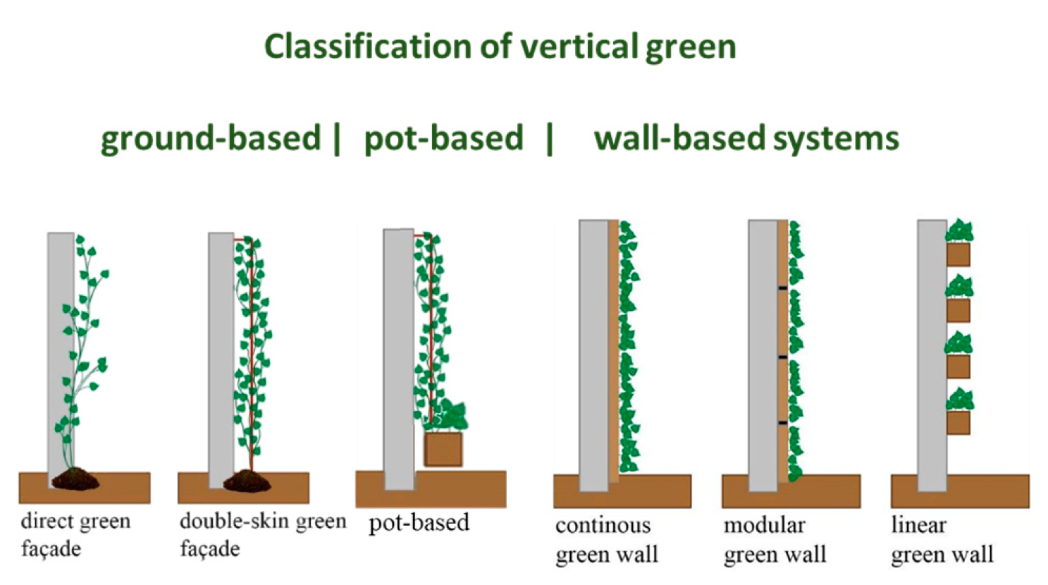
2.3. Greening Building Structures

In general, the combination of wooden trusses and vertical green is not yet widely applied. In this section, the state of the art of vertical greening methods and the currently available system technologies are highlighted. The advantages and the disadvantages of the systems are subsequently discussed.
Roof and facade greening have gained increased recognition within the context of climate change adaptation as well as counteracting urban heat and urban heat islands. The enhancement of urban green infrastructure becoming an integral part of future urban planning has also reached the political mindset, with many nations and cities developing appropriate strategies and guidelines, e.g., the European Green Infrastructure Strategy or the UHI (Urban Heat Island) Strategy of the City of Vienna [24,25,26]. Consequently, modern architecture needs to adapt accordingly, forcing an integration of design-based greening concepts in the architectural planning process at an early stage.
Current research gives evidence on numerous micro-climatic effects, specifically of green facades and their positive impact on urban and household temperature and energy balance [27,28,29]. Trees with high crown or leaf area densities and vegetation with exhaustive coverage on buildings have great significance in terms of shading traffic areas and building surfaces [30,31,32].
Nowadays, a wide range of greening techniques and systems are available not only for the application on new buildings but also for retrofitting. Updated classifications on the systems applicable for vertical greening are provided in [33,34]. A distinction is made between ground-based, pot-based, and wall-based systems (see Figure 7). The first group comprises direct greening with self-adhesive climbers planted in natural soil and double-skin green facades using structural devices as climbing aids (continuous guides or modular trellis [35]). In case of sealed surfaces or application in elevated heights (e.g., terraces, facades with street-orientation and upper-floor retrofit), the same arrangements can be applied in pot-based systems. Wall-based systems have specifically advanced in the past decade, being originally designed for facade green retrofit in elevated heights. They comprise a broad range of variations from textile pockets or bags to planter tiles, trays, modules, or other inert materials. Wall-based systems have the benefit that pre-cultivated, adult plants can be used, ensuring a green effect directly post installation. Modular systems are also easy to integrate as elements in facade construction, whereas greening retrofit solutions for curtain facades (steel or glass constructions) are not yet available.

3. Boundary Conditions

The main buildings of the University of Natural Resources and Applied Life Sciences, Vienna (in short, BOKU, deriving from its German name, Universität für Bodenkultur Wien), are located to the north and the northeast of the Türkenschanzpark (Figure 8, Number 12) in Döbling, Vienna’s 19th district. Since the opening of the first two university buildings of the Türkenschanze campus in 1892, the structure has constantly grown, not only in student and department numbers but also in offered Bachelor of Science (BSc) and Master of Science (MSc) programs, currently resulting in about 12,500 students, 2900 employees [36], 8 BSc, and 26 MSc programs [37]. In order to accommodate the increasing interest, the university campus expanded throughout the 19th district up into the 18th district, with the individual buildings spread out in proximity to one another but not forming an actual closed campus [38]. The assembly of university buildings was interrupted by other educational institutions such as the Modul School of Tourism (Figure 8, number 13), houses and apartment buildings of the Cottagequarter (Figure 8, number 14), and the previously mentioned spacious Türkenschanzpark. In terms of infrastructure, the Peter-Jordan-Straße plays the key role connecting the Gregor Mendel House (Figure 8, number 3), the BOKU main building located on the Gregor-Mendel-Straße in the east, and the Wilhelm Exner House (Figure 9, number 5), housing the university library and located at the intersection with Borkowskigasse in the west. The Türkenwirt, or TÜWI for short (Figure 8, number 1), is one of the most important social centers in the area, located right in the center. The new building (completed in 2018) accommodates various institutes, teaching and studying spaces, an Audimax that can accommodate an audience of up to 400, a canteen where up to 550 meals a day are served, a student run pub, and a farm shop [39]. The wooden lamella facade of the TÜWI (Figure 9, left) faces the Oskar Simony House (Figure 9, right), which was opened in 1904 as a student dormitory and canteen. Over the years, this historic building underwent repeated refurbishments and now offers a home for numerous institutes and classrooms as well as laboratories and workshops in the basement. In the courtyard of the building, which is open towards the street, a well-visited branch of a bakery chain can be found. A pedestrian census carried out in January 2020, mapped out in Figure 10, showed that the Peter-Jordan-Straße was crossed in the area of the intersection with the Dänenstraße on average 500 times in the mid-morning hours (from 09:00 to 11:00), peaking during noon (from 11:00 to 15:00) with 1650, and finishing the afternoon (15:00 to 17:00) off with a further 800 crossings (detailed distribution shown in Figure 11). In addition to the pedestrians, the intersection and the area around it are highly frequented by motorized and non-motorized transportation. The two lanes of the Peter-Jordan-Straße are not only moderately to highly used by individual motorized transport but are also integrated into the public transport network as bus stations for the bus lines 10A, 37A, and 40A. In addition, two heavily used bicycle paths, one on each side of the road, are part of this truly vibrant intersection.
In order to calm this particular area, a separated pedestrian crossing, which will decouple the pedestrian flow from the motorized traffic, improving not only the traffic flow but also pedestrian safety, is in the planning stages. The main challenge of this project was finding the optimal placement and orientation for the passageway regarding the diverse user habits and needs previously described. In the same train of thought, it was also necessary to clarify whether a connection with direct access to the two buildings (TÜWI and Oskar Simony House) would make sense and would be feasible. In addition, the visual contrast between the designs of the two building facades was to be thought of.

4. Conceptual Design

Subsequently, a comprehensive concept especially addressing the following topics: (1) design, (2) location and function, (3) basic ideas regarding the structural design, (4) a possible material choice, (5) a concept for the implementation of digital design, optimization, and automated fabrication for increasing the efficiency, and (6) a possible greening is presented. The claim of the authors is under no circumstances a completeness of the concepts. It is rather a structured reconditioning of the huge number of boundary conditions and serves as a sound basis for further and more detailed design and scientific investigations.

4.1. Design Concept

Similar to a DNA strand, the new pedestrian crossing could stretch over the Peter-Jordan-Straße in a spindle-like rotation around its own axis (implemented by the outer frames mounted to the bridge), bringing relief to the heavily crossed intersection with Dänenstraße by adding a second level to the equation. The design of the outer skin of the proposed bridge and the bridge itself symbolize the transfer of knowledge, an interactive process of transporting, transforming, and expanding the know-how acquired during research and teaching between teachers and their students. This transition process is reflected in the design of the overpass, which gives the impression of morphing from old to new. In terms of design, the twisted lamellar frames of the outer skin refer to the modern face of the new TÜWI building, while the load-bearing structure deduced from traditional construction methods acts as a backbone referencing the historical background of the university (Figure 12).

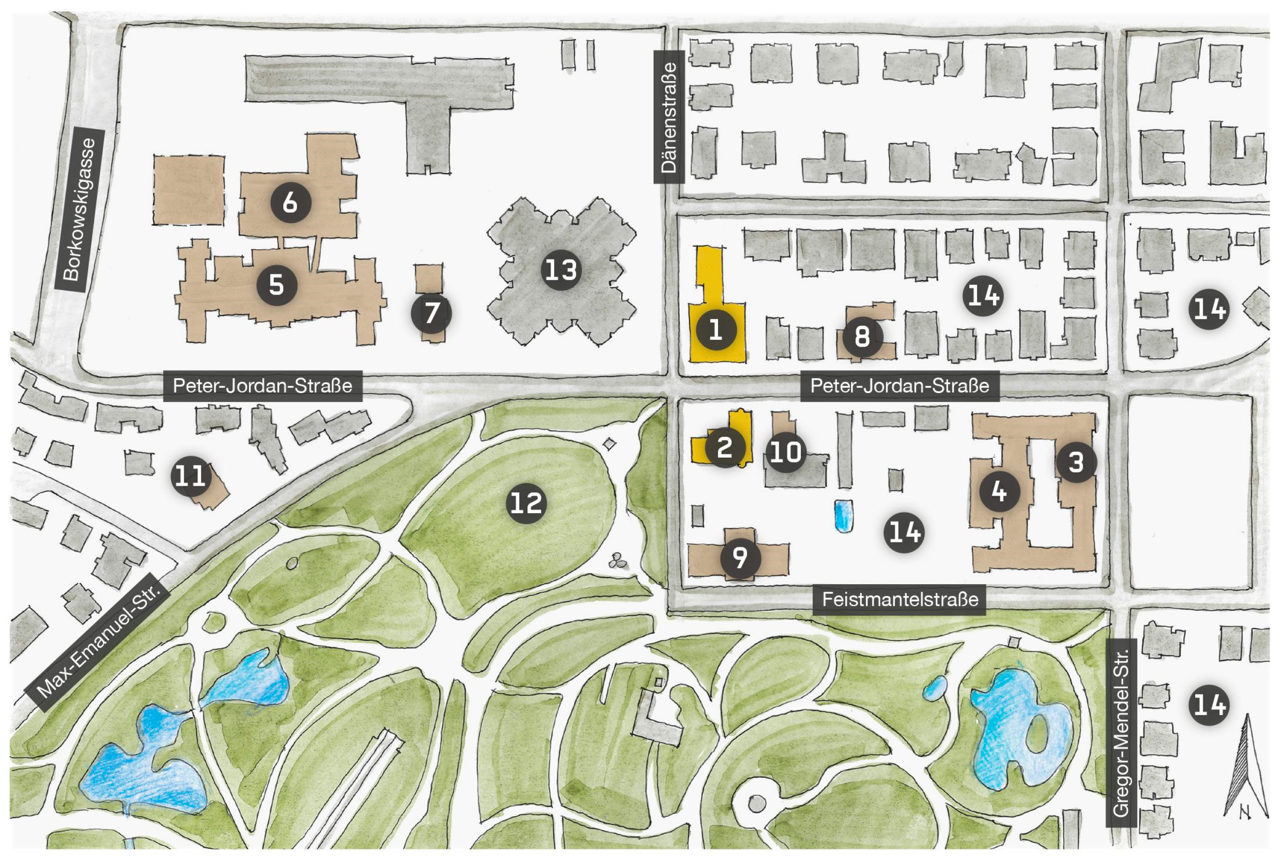
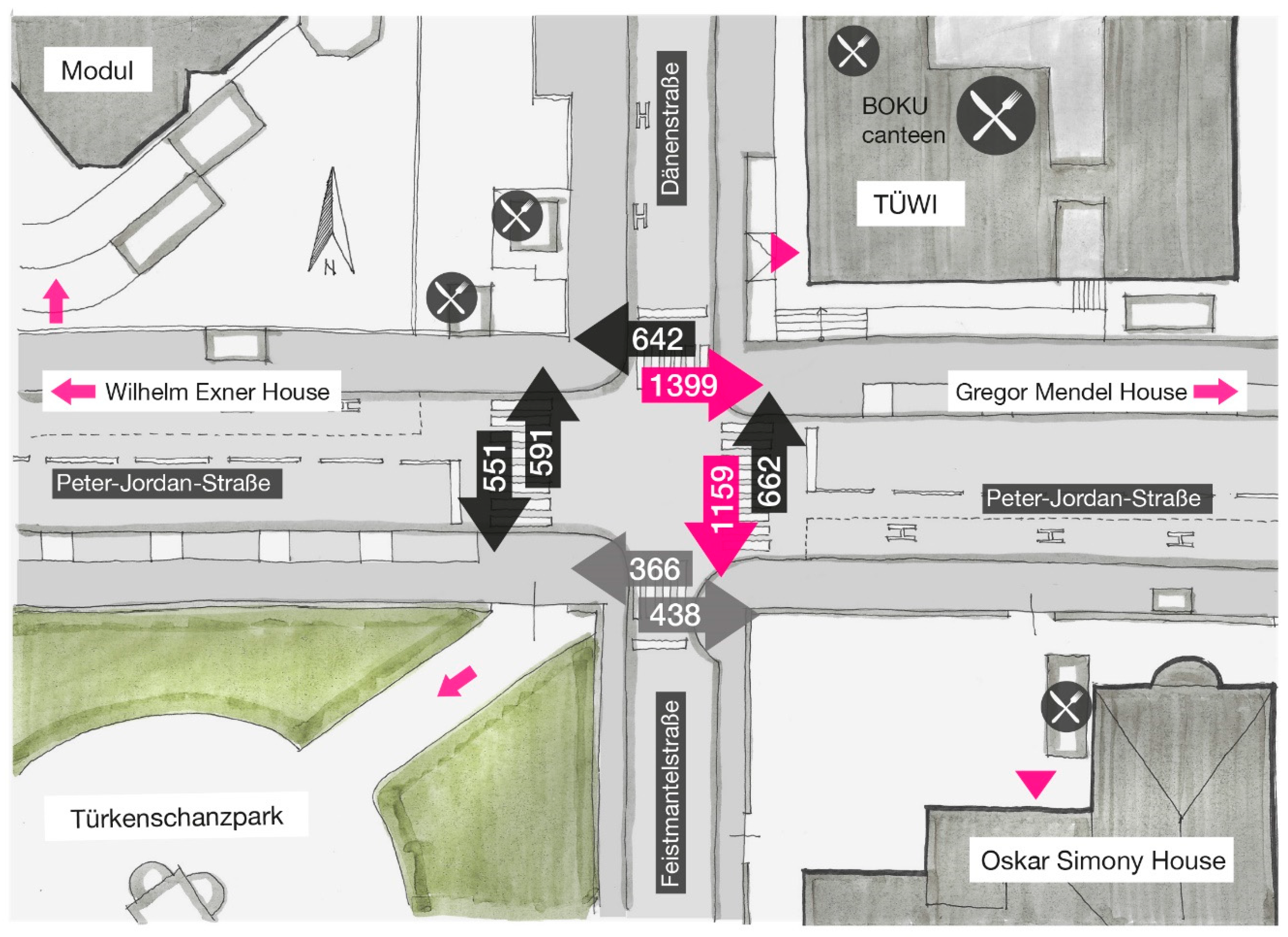
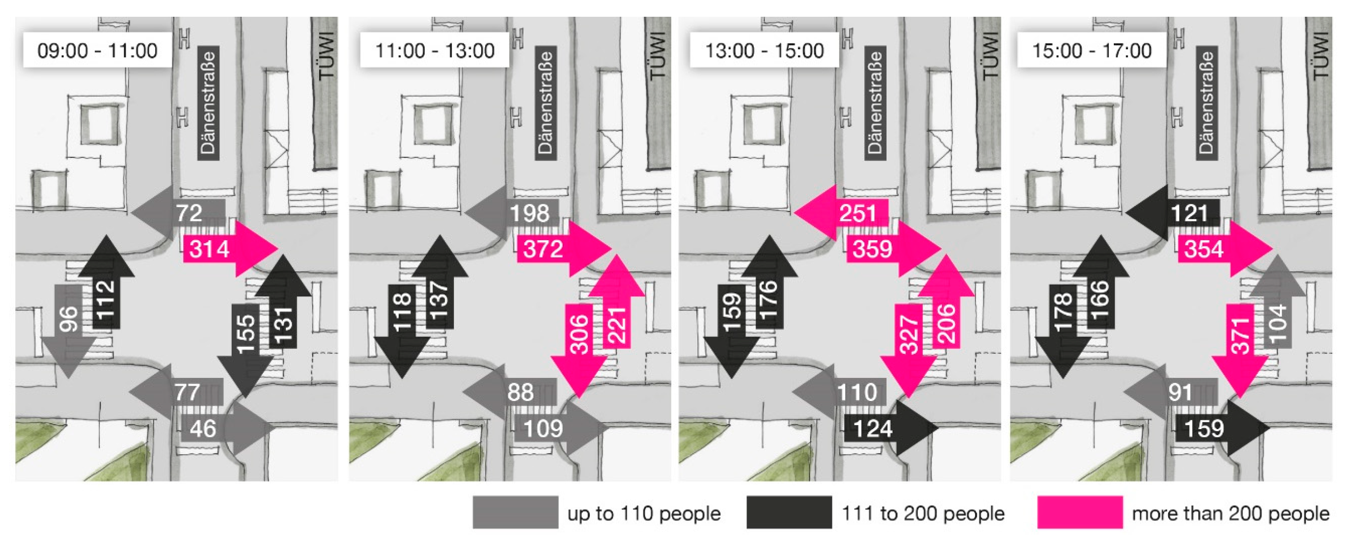
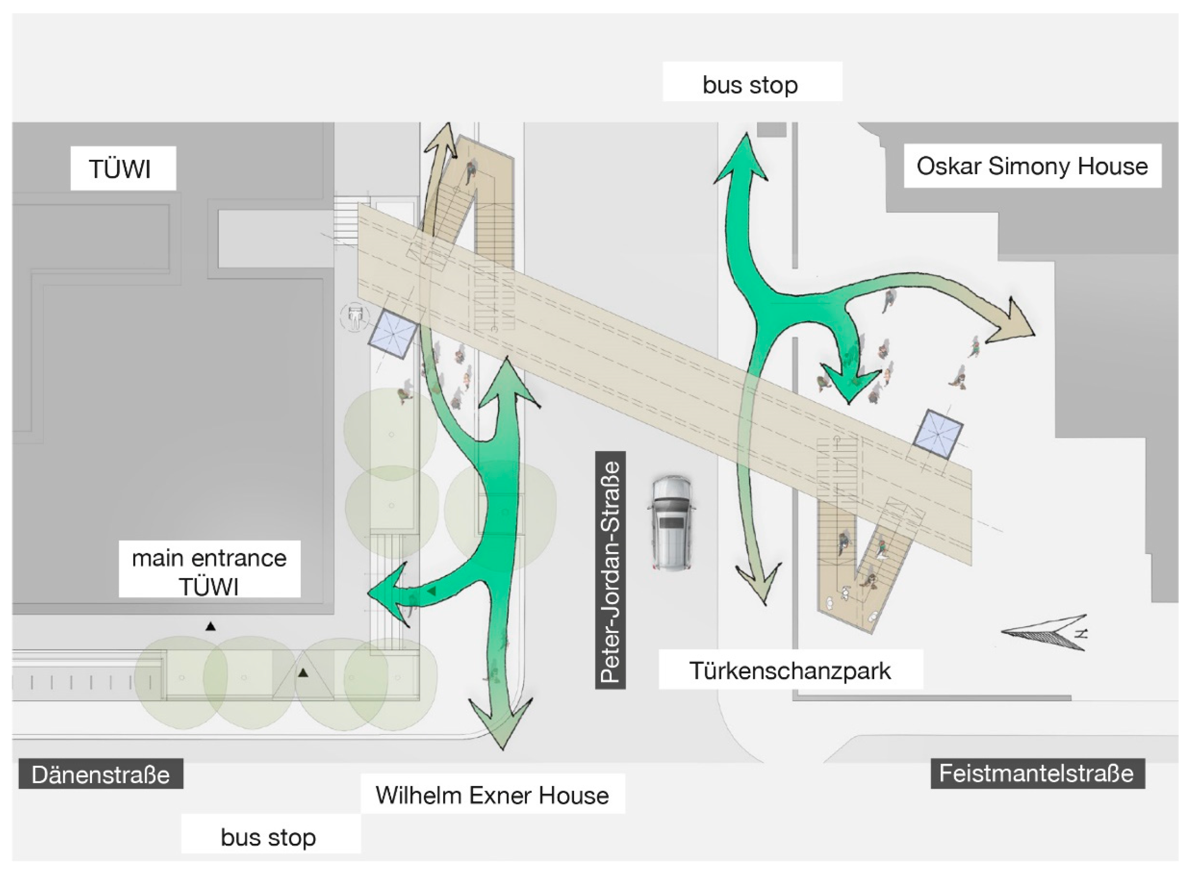
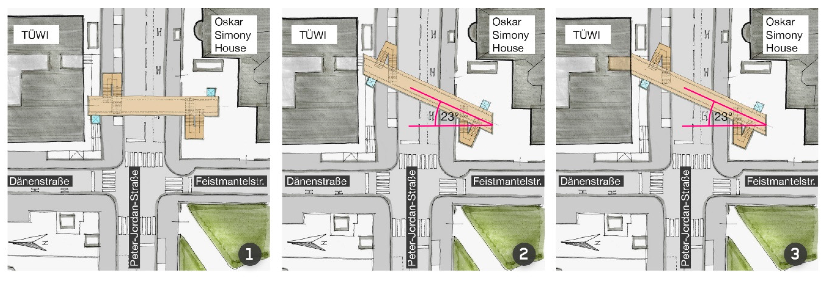
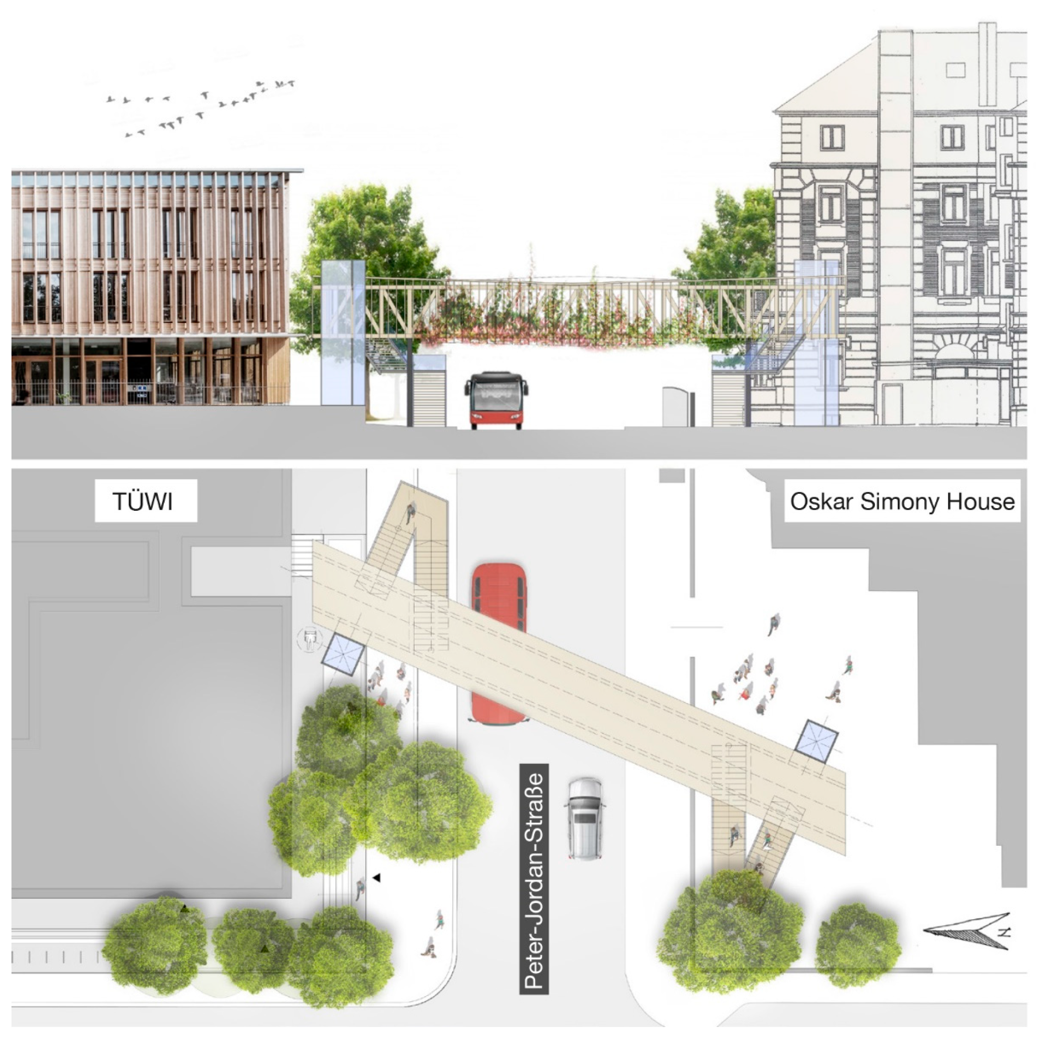
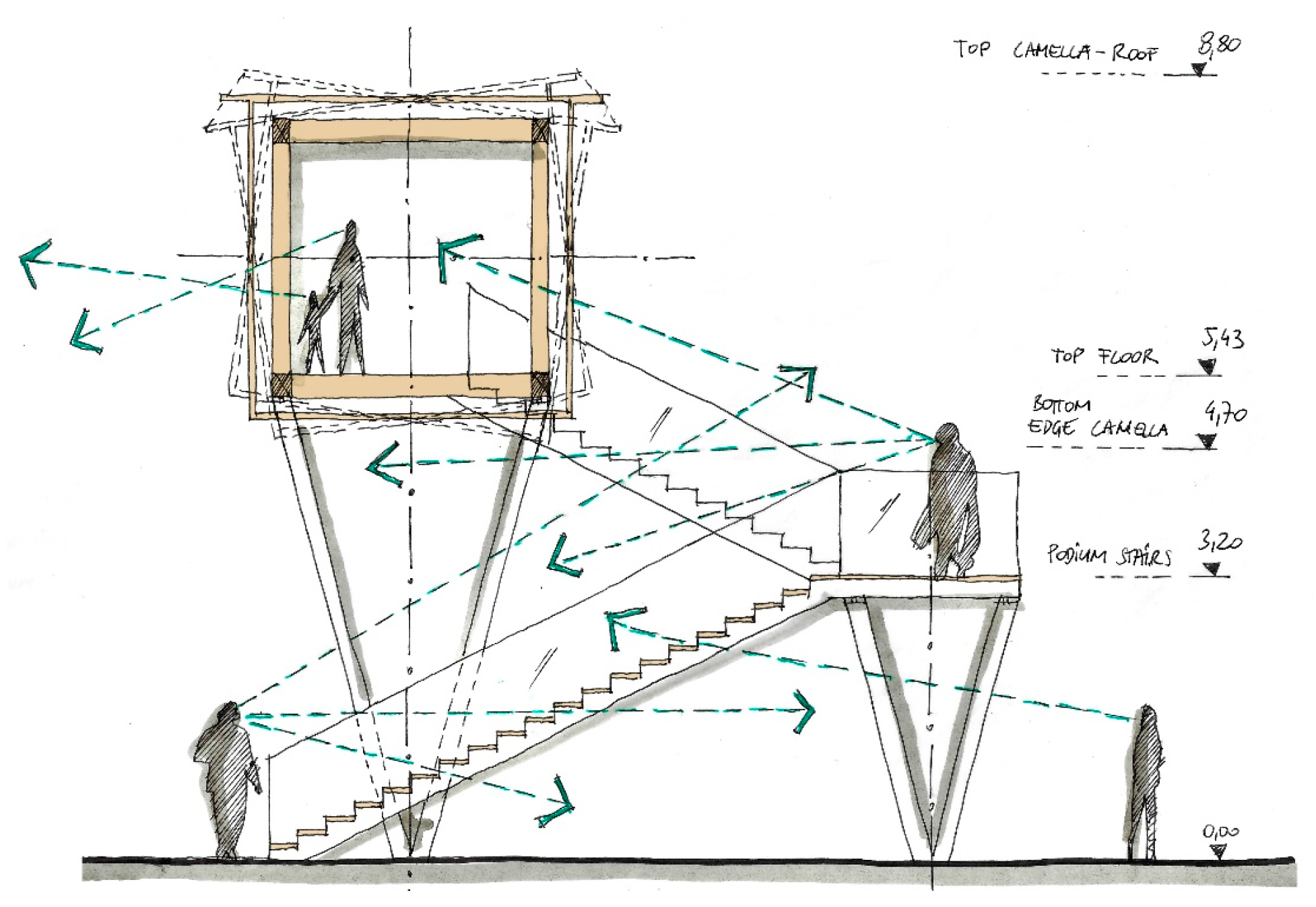
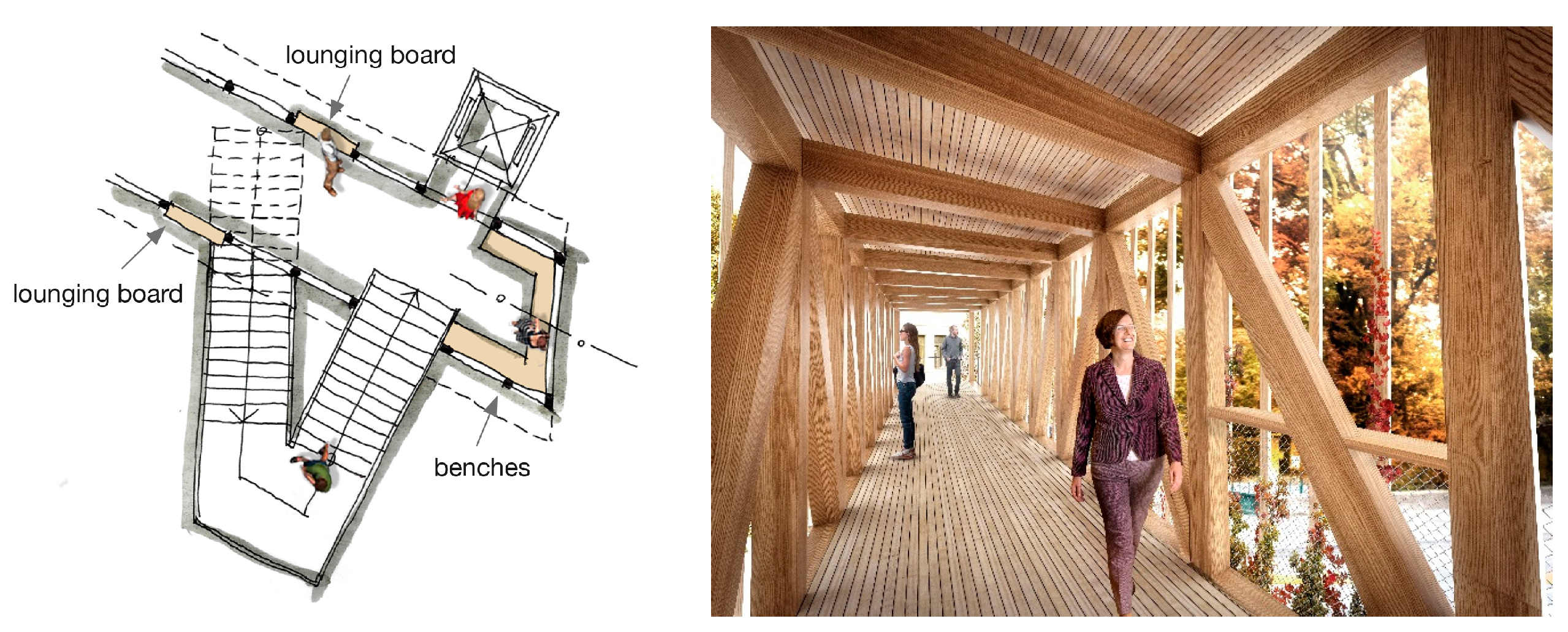
4.2. Location and Fuction

The concept describes the new pedestrian crossing above the Peter-Jordan-Straße to the west of the intersection with Dänenstraße in the area with the highest noted frequency of crossings during the day. The structure will gather the distributed pedestrian flows and allow safe and quick passage. The two flights of stairs have their entry points with opposite orientations, each aligned towards the main flow direction (Figure 13).
The bridge could either be positioned orthogonally (Figure 14, number 1) or at an angle (Figure 14, number 2) to the Peter-Jordan-Straße, freestanding or connected to the buildings nearby. Compared to orthogonal positioning, the rotated version appears more dynamic overall (Figure 15). While the steps and the lower segments of both flights of stairs remain aligned parallel to the course of the street in both versions, allowing a good access for the pedestrian flow, the axis of the “dynamic” bridge is rotated by 23° to the east with reference to the Oskar Simony House. Apart from opening up the access area to the bridge itself, the rotation around the longitudinal axis gives the approaching individuals the impression of gentle wave-like movement of the lamellar casing (Figure 16).
As mentioned before, a connection with direct accesses to the TÜWI building and the Oskar Simony house (Figure 8, number 2) was considered and investigated with regard to their functional advantages and feasibility. While a connection to the historical Oscar Simony House did not seem to make much sense due to the height of the building floors and the effected floor plan, a direct link to the TÜWI, with its numerous public facilities, seemed reasonable. A possible connection point was quickly found in the Peter-Jordan-Straße facing recess on the first floor.

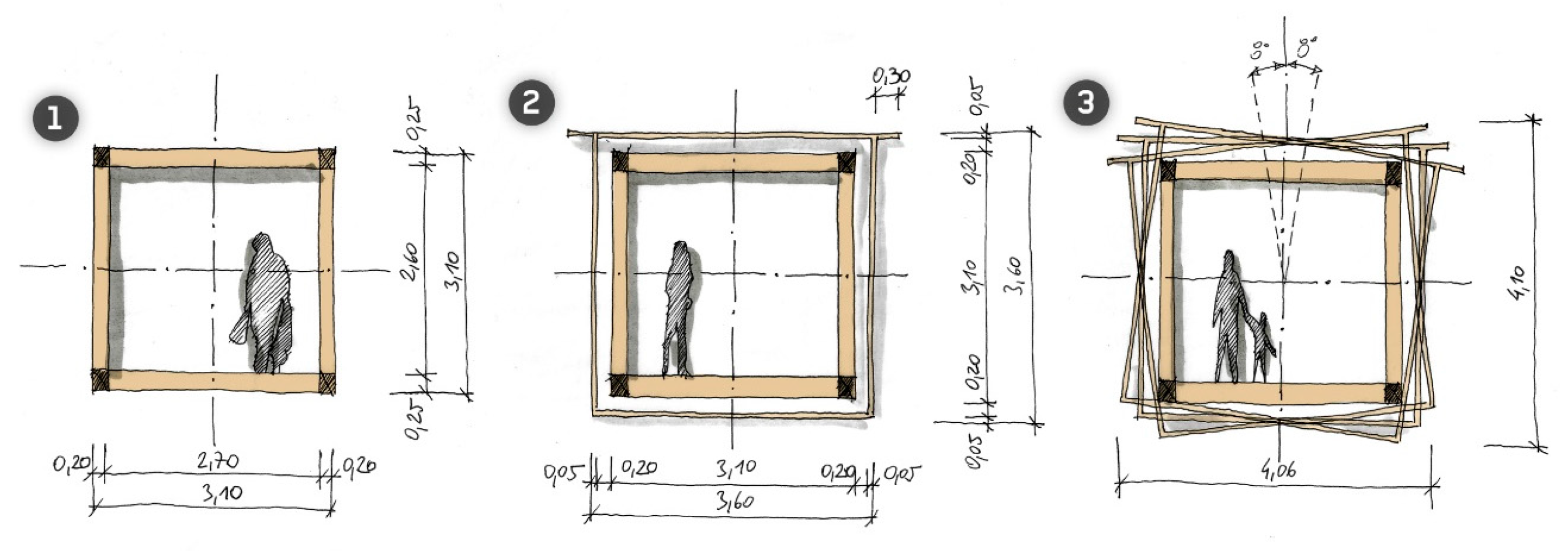
4.3. Structural Design

The structural design of the bridge consists of two floor-to-ceiling timber trusses, which are designed as single span girders with a length of 34 m as the primary structural system. Timber beams connect the two trusses to each other, creating a three-dimensional structure, and act as the secondary structural system. A parametric planning approach containing an optimization algorithm for the geometry of the main truss in combination with automated production data generation will be implemented to further improve the truss design. The optimization specifically takes the dimensions of the truss members and the geometry (slope combined with the distances of the vertical members) into account. Within the parametric planning approach, the global geometry serves as basis for the local connections. These are subsequently optimized also in an automated way as part of the continuous digital process chain. Based at the found geometry, the tool path and the subsequent g-code are generated. The advance of the approach is that the optimal geometry can be found, and eventual adaptions to changing boundary conditions can be integrated promptly until the final g-code generation for the machine.
Surrounding this supporting core, with inner dimensions of 2.70 m by 2.60 m (headroom up to the lower edge of the truss) (Figure 16, number 1), 110 lamellar frames are mounted at a horizontal and a vertical distance of 300 mm from the main axes, resulting in external dimensions of 3.60 m by 3.60 m of each single frame (Figure 16, number 2). Starting from the middle of the bridge, the individual frames are twisted to both sides by a total of 8°, with the rotation being mutual in both directions (Figure 16, number 3).
The bridge’s load-bearing structural system will be built, according to function and material, as a traditionally built construction. A roof including eaves is considered to protect the structure from driving rain and to serve as constructive wood protection. Horizontal surfaces are avoided. The outer skin as well as all access areas and facilities are to be constructed as slenderly and delicately as possible, leaving the backbone of the structure visible throughout the entire length and allowing all user and passers-by, whether on foot, on bicycle, or motorized maximum insight and view. The transparency of the structure not only prevents blind spots that can cause safety issues or areas that can be polluted but also allows for an optimal optical integration of the construction into its heterogeneous environment (Figure 17).
In terms of sustainability and in relation to the direct environment, a renewable material with a high resistance to weather influences is chosen: larch wood, equal to the Rosannabrücke. The timber trusses, being the load-bearing structure, will consist of larch glue laminated timber (glulam). The substructure of the roof, the floor, and the individual steps will also be made out of larch wood. With wood being the main material of choice, the design concept of integrations is well reflected.
The two flights of stairs will be supported on both sides by two V-shaped pillars made of ultra-high-performance concrete (UHPC), a material that allows small dimensions without compromising on load-bearing capacity or durability. At each end of the bridge, a lift in a glass/steel finish can be found in addition to the staircases, which are given a lightness through the open design using glass railings and free-floating steps (Figure 18).
The bridge will be illuminated indirectly using glare-free lights integrated into the trusses or the staircases. The ceiling and the floor paneling will consist of narrow strips of solid larch wood installed in a longitudinal direction of the bridge, underlining the dynamic of the alignment.

4.4. Material and Facilities

Depending on the design, the outer skin of the overpass can include trellis made of (larch) wood or steel. If greened, the structure would additionally contribute to the surrounding microclimate and reference nicely to the nearby Türkenschanzpark. Furthermore, the vegetation lends a supplementary dynamic character due to its seasonal changes in appearance (Figure 18). The structure should not only be seen as a means for crossing but should also invite the passengers to linger, experience, and reflect. Areas of deceleration will be provided through the arrangement of resting areas throughout the span. The open spaces created at the ends of the bridge and in between the truss elements will be equipped with benches and consoles (Figure 19, left). An additional bonus is the view when coming from the Oskar Simony house presenting an exceptional perspective on the Türkenschanzpark (Figure 19, right).
Finally, the symbolic character of such a structure should also be considered. The resulting gate-like installation marks an infrastructurally salient point of the most important access axis of the Türkenschanze campus. At the same time, the bridge symbolically connects the traditional past of the University of Natural Resources and Life Sciences with its dynamic present. The sustainable building materials, the innovative production approach, and the greening of the outer casing also represent the spirit of the institution from this point onward in the public eye.

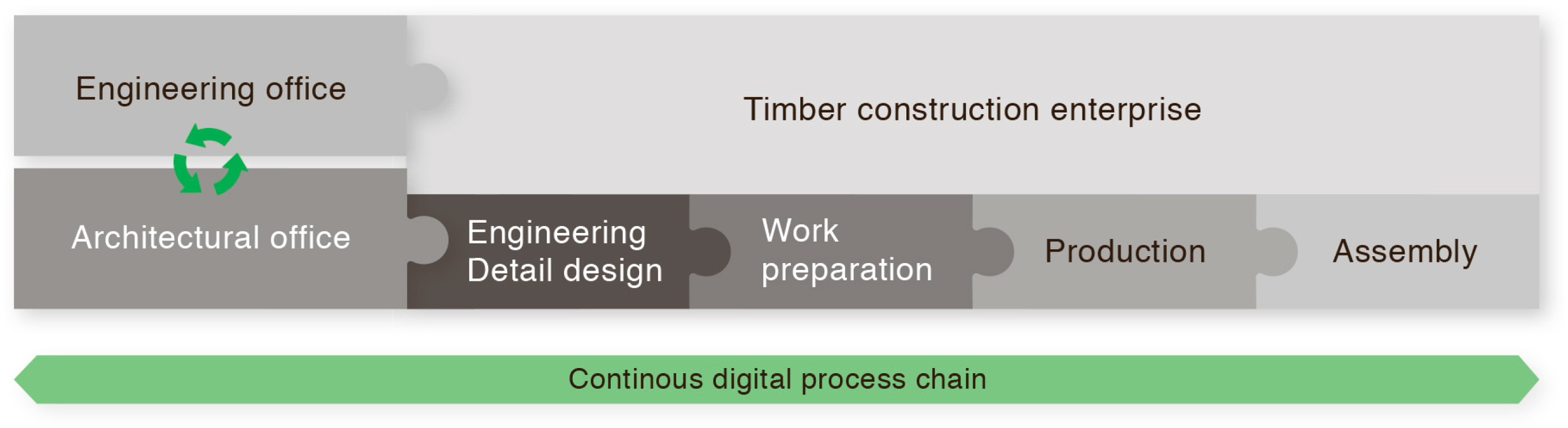
4.5. Digital Design, Optimization, and Automated Prefabrication Concept

Engineered timber products such as laminated timber and cross laminated timber provide advantageous properties in comparison to classic sawn timber [40,41,42]. Wood is a natural inhomogeneous anisotropic material with discontinuities due to defects such as pitch pockets, branches, fiber twist, etc. The machining process and the gluing allow for a compensation of these defects to obtain smoother and better material properties. In addition, geometry deviations resulting from changes of the equilibrium moisture can be reduced. The drawback is that the production process of these products is accompanied by many subtractive machining processes. If sawn timber is produced from a tree trunk, the yield rate lies at about 55%, and the rest are by-products. The yield rate sinks to 25–30% within the further processing to laminated timber. Consequently, good mechanical properties and advantageous behavior regarding geometric deformations entail a low yield percentage of the raw material.
Considering the low yield percentage, the structural optimizatison of building components made from engineered timber products such as laminated and cross laminated timber instead of classic sawn timber becomes of outmost importance. The aim is to industrialize the design and the prefabrication processes of wood constructions by using a continuous digital process chain to enable efficient implementation of this valuable material. The aspired process chain, from design to assembly, is shown in Figure 20. The digitization of all interfaces allows for a very fast and reliable workflow from first design to the generation of the production data. The direct digital link also allows for a fast and easy consideration of changes within the design process. Different approaches for this purpose were already developed, inter alia, at the ETH Zürich, the EPFL Lausanne, and at University of Stuttgart [43,44,45,46,47,48,49,50,51]. All found solutions within these impressive research and application projects have one thing in common—they represent individual digital design and production processes for the respective task or project.
The aim of the authors is to develop a standardized procedure for timber trusses for easy use in broad application. The development is split in four subprocesses: (1) optimization of the connections, (2) optimization of the production technology, (3) optimization of the digital and the human interfaces (during design and production), and (4) algorithm-based optimization of the structural design. Initial research addressing (1), (2), and (3) can be found in [52].

4.6. Greening Concept

In this chapter, the potential for the application of (climbing) plants on wooden trusses and the combination of wooden trusses with vertical green is pointed out. Wooden trusses can be designed in a countless number of sizes and shapes and have noticeable potential for modular pre-production and fitting with plants and planters. Whether hitherto commonly applied truss design meets the requirements for plant attachment and long-term plant habitats is yet unanswered and is put in the center of interest.
The combination of building green on constructional timber was rather uncommon until now, making scientific data on the topic nonexistent. The reservations of the construction sector regarding the compatibility of plants with wooden surfaces imply that they impair surfaces and have adverse effects on the constructive elements and the load-bearing assemblies and are not based on any actual reports or research. However, wooden climbing aids and trellis have been used traditionally in the gardening sector, as have wooden pots and planters. Wooden pergolas are also commonly greened with climbing plants for providing natural roofing and shading. Popular plants used are varieties of roses, jasmine, wisteria, honeysuckles, and many more.
Applying vertical green on wooden trusses means exploring new frontiers and may require a more profound review of the plant species and the planting equipment. The current approach to roof greening is specifically focused on the planting substrates, which are technically sophisticated and specifically developed to fulfill a series of requirements such as light weight and water storage capacity with simultaneous permeability. Nutrient availability is important, as are retention buffer and drainage capacities, since rainwater management on building surfaces has become a major issue and needs deeper consideration when designing planters and planting elements for building green. This is just as valid for all versions of vertical green and needs to be transferred to greening of wooden trusses.
A further decisive factor is the irrigation management. In contrast to green roofs, green facades and specifically pot-based and wall-based systems need artificial irrigation. The quantity of water supply depends on various external and internal factors: meso- and microclimate and weather conditions, exposition, plant species, substrate characteristics, and irrigation system (single or multiple loops). Drip-irrigation is considered state of the art, adding the same water quantities in regular intervals and disrespecting the actual demand. However, up-to-date technologies use multiple-circuit and sensor-based systems, with water supply only provided when substrate moisture drops below a certain threshold. This allows for a more resource-saving management, water savings of up to two thirds, and prevents water overflows or drowning of the plants. The latter is as decisive for plant survival as is avoiding droughts, but preventing overflows is crucial for facade material and surface protection. Water damage is specifically critical in case of timber constructions and timber trusses and must be diligently anticipated and considered with particular care.
Water damage can theoretically result from constantly wet leaves that are in permanent contact with the timber surface. Options to avoid this are (a) double-skin systems with trellis and climbing aids and adequate spacers or (b) appropriate roofing that should be considered in the construction design or can even be used as a design element. Interesting alternatives to upward climbing plant systems are seen in (c) hanging plant systems and similar configurations. They have great potential as shading curtains and should be tested with respect to design-based branch-guiding elements and growth characteristics. As the wooden bridge will be functioning as an overpass, the particular street situation requires the compliance with the legal requirements in terms of structure gauge. This is of specific relevance for management operations and needs particular attention in the design setup.
Following these considerations, there is an obvious set of criteria decisive for both the plant and the truss design that need to be defined and specified at an early planning stage. From this, a series of research questions arise that should be addressed and clarified in a pretest setting:
(1)
How can the requirements for plant attachment and guides be fulfilled for the options (a), (b), and (c)?
(2)
How can they be integrated in the truss design?
(3)
How can the timber–plant interaction be characterized?
(4)
Is wetting emerging and resulting from leaf attachment and climbing organs?
(5)
Does surface plant contact cause serious impact to the timber and the stability performance?
(6)
Can the long-term plant habitats be assessed and modeled regarding aesthetic integration, material protection, and microclimatic benefits?

5. Summary and Outlook

The present contribution described the concept for the digital design and the automated manufacturing of a greened wooden truss bridge for pedestrians in the area of the University of Natural Resources and Life Sciences, Vienna based on traditional building techniques.
The durability of a wooden bridge is strongly related to a well thought out constructive wood protection. Therefore, two traditional Austrian wooden bridges, the Rosannabrücke in Tyrol (Austria) and the Gosauzwangbrücke in Upper Austria (Austria), representing both a good and a bad example of constructive wood protection, were presented. The Rosannabrücke, built in 1764, represents the oldest Austrian wood bridge still in service. A clear result of the comparison between the two bridges can be found in the importance of a constructive wood protection, especially for load bearing structures. Therefore, centuries-old craft knowledge regarding this topic has to be conserved and shared with future generations. The scientific reconditioning regarding this topic is also limited due to the big influence of different boundary conditions (climate, local, and global location). As concluding and general applicable rules derived from the preliminary comparative study, the protection of horizontal surfaces, of grain-cut-timber, and of the windward side faces can be mentioned. It is often performed traditionally to consider wear elements in design that are renewed periodically.
The study identified the boundary conditions for the design concept and analyzed the spatial situation as well as the pedestrian flows in the area of interest. With an average rate of 1650 crossings within the midday peak, the need to relieve this area is evident. The heterogeneous campus situation at the Türkenschanze suggests a structure that reflects the special and universal character of the institution BOKU in the public space in terms of construction and design. Through early and intensive integration of technical and architectural design disciplines in a multidisciplinary team, a design was created that, in addition to the technical requirements, also integrated design concerns such as the optical integration of the pedestrian overpass into its inhomogeneous surroundings or the spindle-shaped twisting of the enclosure as a symbolic gesture for the transfer of knowledge in general.
After focusing on the design, digital design and automated manufacturing concepts were introduced. It can be derived that the current process chains in constructive timber engineering are characterized by a huge number of digital and human interfaces, leading to inefficiency and a high error rate. The authors presented a more efficient concept for the process chain, which reduced human and digital interfaces in order to increase ecologic and economic efficiency. Structural optimization and a fully digital process chain combined with efficient production techniques are considered key methods. The clear objective is to develop a workflow for widespread use instead of individual structures. Within the present contribution, the basic needs of improvement were identified and serve as a basis for more detailed research. Areas with required improvement were defined, which will be presented in a more specific scientific work in separate papers.
The presented design study brought to light that scientific work regarding the greening of wooden trusses is non-existent and that a greening concept needs to be addressed from experimental and scientific points of view. Thus, a number of research questions regarding the influence of greening on the load-bearing wood elements were formulated, serving as basis for further empirical investigations.
Future work will focus on a deeper investigation of the constructive wood protection by analyzing an increased number of existing structures, by setting up a structured database, and by monitoring them over a period greater than five years. This should allow for setting a scientific basis for the assessment of the constructive wood protection and will allow for structured recommendations within construction of wood structures.
Regarding the topic of industrialization of the process chain for the construction of wood structures, an automated geometry optimization algorithm will be developed and directly linked to the generation of production data. Further research focus will be set on the development of highly efficient connection technologies for frame members under compressive and tensile loads. The full process will be evaluated within the production of a scaled bridge girder. The load-bearing capacity of the girder will be analyzed subsequently in destructive tests. Apart from that, the authors strive to push research forward regarding the combination of wooden trusses with planting. Therefore, a test setup will be constructed in summer 2020, and different approaches of vertical green will be tested to evaluate the potential of the approach.

Author Contributions

The general strategy as well as the general concept for the bridge was developed by B.K. He was in addition responsible for the structural design as well as the digital design, optimization, and automated prefabrication concept. M.R. and A.S. were responsible for the architectural and design concept. R.S. contributed with the findings around the greening of structures. F.I. contributed with the comparison of the two traditional wood bridges (Rosannbrücke and Gosauzwangbrücke). All authors have read and agreed to the published version of the manuscript.

Funding

This research received no external funding.

Acknowledgments

The authors gratefully acknowledge the BOKU rectorate for the good cooperation. The open access publication was supported by BOKU Vienna Open Access Publishing Fund.

Conflicts of Interest

The authors declare that they have no conflict of interest.

References

  1. Lutz, W.; Sanderson, W.; Scherbov, S. The end of world population growth. Nature 2001, 412, 543–545. [Google Scholar] [CrossRef] [PubMed] [Green Version]
  2. World Wide Fund for Nature. WWF Living Forests Report: Chapter 1-Forets for a Living Planet; WWF: Gland, Switzerland, 2012; ISBN 978-2-940443-32-1. [Google Scholar]
  3. World Wide Fund for Nature. WWF Living Forests Report: Chapter 4-Forests an Wood Products; WWF: Gland, Switzerland, 2012; ISBN 987-2-940443-32-1. [Google Scholar]
  4. Moreno, E.L. Urbanization and Development: Emerging Futures: World Cities Report 2016; UN Habitat: Nairobi, Kenya, 2016. [Google Scholar]
  5. Rosenzweig, C.; Solecki, W.; Hammer, S.A.; Mehrotra, S. Cities lead the way in climate–change action. Nature 2010, 467, 909–911. [Google Scholar] [CrossRef] [PubMed]
  6. Vox, G.; Blanco, I.; Schettini, E. Green façades to control wall surface temperature in buildings. Build. Environ. 2018, 129, 154–166. [Google Scholar] [CrossRef]
  7. Weixelbaumer, V.; Zluwa, I.; Weihs, P. Roof shelter environment: An experimental study about increasing thermal comfort on a rooftop terrace by combining photovoltaic energy production and greenroofs. In Hildegard Gremmel-Simon, Proceedings of the Gebäude der Zukunft? vernetzt-digital-ökosozial, Pinkafeld, Austria, 22–23 November 2018; Leykam, Buchverlagsgesellschaft, m.b.H: Pinkafeld, Austria, 2018. [Google Scholar]
  8. Speak, A.F.; Rothwell, J.J.; Lindley, S.J.; Smith, C.L. Rainwater runoff retention on an aged intensive green roof. Sci. Total Environ. 2013, 461, 28–38. [Google Scholar] [CrossRef] [PubMed]
  9. Todorov, D.; Driscoll, C.T.; Todorova, S. Long-term and seasonal hydrologic performance of an extensive green roof. Hydrol. Process. 2018, 32, 2471–2482. [Google Scholar] [CrossRef]
  10. Hoelscher, M.-T.; Nehls, T.; Jänicke, B.; Wessolek, G. Quantifying cooling effects of facade greening: Shading, transpiration and insulation. Energy Build. 2016, 114, 283–290. [Google Scholar] [CrossRef]
  11. Jesionek, K.; Bruse, M. Impacts of vegetation on the microclimate: modeling standardized building structures with different greening levels. In Proceedings of the Fifth Int. Conf. on Urban Climate, Lodz, Poland, 1–5 September 2003; pp. 1–5. [Google Scholar]
  12. Elsadek, M.; Liu, B.; Lian, Z. Green façades: Their contribution to stress recovery and well-being in high-density cities. Urban For. Urban Green. 2019, 46, 126446. [Google Scholar] [CrossRef]
  13. Başdoğan, G.; Çığ, A. Ecological-Social-Economical Impacts of Vertical Gardens in the Sustainable City Model. Yüzüncü Yıl Üniversitesi Tarım Bilimleri Dergisi 2016, 26, 430–438. [Google Scholar]
  14. Yan, H.; Wang, X.; Hao, P.; Dong, L. Study on the microclimatic characteristics and human comfort of park plant communities in summer. Procedia Environ. Sci. 2012, 13, 755–765. [Google Scholar] [CrossRef] [Green Version]
  15. Mitterer, S. Dokumentation Strengen Rosannabrücke, 2015.
  16. Seifert, A. Im Zeitalter des Lebendigen, S. 138; Müllersche Verlagshandlung: Munich, Germany, 1943. [Google Scholar]
  17. Hofkammerarchiv Wien Camerale, Fasz. 8, rot 248, 120 ex junio. 1972.
  18. Idam, F. 13.000 Rohre für den Soletransport. Industrie-kultur, April 2009; 16–17. [Google Scholar]
  19. Hofkammerarchiv Wien. Plan Sig. H-112 aus der Handschrift Nr. 627, Relation ü.d. 1781 Skgt. Visitation d. Hofschreiberamtes und Marktbericht Hallstatt; Hofkammerarchiv Wien: Wien, Austria, 1781. [Google Scholar]
  20. Schraml, C. Das oberösterreichische Salinenwesen von 1750 bis zur Zeit nach den Franzosenkriegen; Wien Government: Wien, Austria, 1934; p. 123.
  21. Fellner, A. Bergmännisches Handwörterbuch für Fachausdrücke im Salzbergbau-und Sudhüttenwesen; Wien Government: Wien, Austria, 1999.
  22. Kommunal. Wanderweg und Sole-Pipeline; Österreichischer Kommunalverlag, Wien ISSN: 1605-1440, issue 09/17, 2017. Available online: https://gemeindebund.at/website2016/wp-content/uploads/2017/10/kommunal_9-2017.pdf (accessed on 2 February 2020).
  23. Zubizarreta, M.; Cuadrado, J.; Orbe, A.; García, H. Modeling the environmental sustainability of timber structures: A case study. Environ. Impact Assess. Rev. 2019, 78, 106286. [Google Scholar] [CrossRef]
  24. Magistrat der Stadt Wien; Wiener Umweltschutzabteilung MA22. Urban Heat Islands–Strategieplan Wien; Wiener Umweltschutzabteilung: Wien, Austria, 2015.
  25. European Commission. Communication from the Commission to the European Parliament, the Council, the European Economic and Social Committee and the Committee of the Regions-Green Infrastructure (GI)—Enhancing Europe’s Natural Capital. COM; European Commission: Brussels, Belgium, 2013. [Google Scholar]
  26. United States Environmental Protection Agency. Greening EPA. Available online: https://www.epa.gov/greeningepa (accessed on 20 February 2020).
  27. Bustami, R.A.; Belusko, M.; Ward, J.; Beecham, S. Vertical greenery systems: A systematic review of research trends. Build. Environ. 2018, 146, 226–237. [Google Scholar] [CrossRef]
  28. Yang, F.; Yuan, F.; Qian, F.; Zhuang, Z.; Yao, J. Summertime thermal and energy performance of a double-skin green facade: A case study in Shanghai. Sustain. Cities Soc. 2018, 39, 43–51. [Google Scholar] [CrossRef]
  29. Hunter, A.M.; Williams, N.S.G.; Rayner, J.P.; Aye, L.; Hes, D.; Livesley, S.J. Quantifying the thermal performance of green façades: A critical review. Ecol. Eng. 2014, 63, 102–113. [Google Scholar] [CrossRef]
  30. Scharf, B.; Kraus, F. Green roofs and greenpass. Buildings 2019, 9, 205. [Google Scholar] [CrossRef] [Green Version]
  31. Sanusi, R.; Johnstone, D.; May, P.; Livesley, S.J. Microclimate benefits that different street tree species provide to sidewalk pedestrians relate to differences in Plant Area Index. Landsc. Urban Plan. 2017, 157, 502–511. [Google Scholar] [CrossRef]
  32. Gillner, S.; Vogt, J.; Tharang, A.; Dettmann, S.; Roloff, A. Role of street trees in mitigating effects of heat and drought at highly sealed urban sites. Landsc. Urban Plan. 2015, 143, 33–42. [Google Scholar] [CrossRef]
  33. Medl, A.; Stangl, R.; Florineth, F. Vertical greening systems–a review on recent technologies and research advancement. Build. Environ. 2017, 125, 227–239. [Google Scholar] [CrossRef]
  34. Radić, M.; Dodig, M.B.; Auer, T. Green Facades and Living Walls—A Review Establishing the Classification of Construction Types and Mapping the Benefits. Sustainability 2019, 11, 4579. [Google Scholar] [CrossRef] [Green Version]
  35. Manso, M.; Castro-Gomes, J. Green wall systems: A review of their characteristics. Renew. Sustain. Energy Rev. 2015, 41, 863–871. [Google Scholar] [CrossRef]
  36. University of Natural Resources and Life Sciences BOKU-Daten und Fakten 2018. Available online: https://boku.ac.at/fileadmin/data/Zielgruppen/ZahlenDatenFakten.pdf (accessed on 2 February 2020).
  37. University of Natural Resources and Life Sciences BOKU. Available online: https://boku.ac.at/ (accessed on 2 February 2020).
  38. Unviversity of Natural Resources and Life Sciences BOKU-site map location Türkenschanze. Available online: https://boku.ac.at/fileadmin/data/H05000/H12000/Baum_2012/B-_International_Students_coming_to_BOKU/I-_Wie_plane_ich_mein_Studium_an_der_BOKU/3_Map_Tuerkenschanze.pdf. (accessed on 2 February 2020).
  39. Bundesimmobiliengesellschaft, m.b.H. Detail-Bundesimmobiliengesellschaft. Available online: https://www.big.at/projekte/tuewi-boku-wien/ (accessed on 2 February 2020).
  40. Bodig, J.; Jayne, B.A. Mechanics of Wood and wood Composites; Van Nostrand Reinhold: New York, NY, USA, 1982; ISBN 978-0-442-00822-2. [Google Scholar]
  41. Möller, E. Tendenzen im Holzbau. Bautechnik 2013, 90, 42–46. [Google Scholar] [CrossRef]
  42. Shmulsky, R.; Jones, P.D. Forest Products and Wood Science: An Introduction; John Wiley & Sons: Hoboken, NJ, USA, 2011; ISBN 978-0-8138-2074-3. [Google Scholar]
  43. Helm, V.; Willmann, J.; Gramazio, F.; Kohler, M. In-situ robotic fabrication: Advanced digital manufacturing beyond the laboratory. In Gearing up and accelerating cross-fertilization between academic and industrial robotics research in Europe; Röhrbein, F., Veiga, G., Natale, C., Eds.; Springer International Publishing: Cham, Switzerland, 2014; pp. 63–83. [Google Scholar]
  44. Søndergaard, A.; Amir, O.; Eversmann, P.; Piskorec, L.; Stan, F.; Gramazio, F.; Kohler, M. Topology optimization and robotic fabrication of advanced timber space-frame structures. In Proceedings of the Robotic Fabrication in Architecture, Art and Design, Sydney, Australia, 18–19 March 2016; pp. 190–203. [Google Scholar]
  45. Willmann, J.; Knauss, M.; Bonwetsch, T.; Apolinarska, A.A.; Gramazio, F.; Kohler, M. Robotic timber construction—Expanding additive fabrication to new dimensions. Autom. Constr. 2016, 61, 16–23. [Google Scholar] [CrossRef]
  46. Thoma, A.; Adel, A.; Helmreich, M.; Wehrle, T.; Gramazio, F.; Kohler, M. Robotic fabrication of bespoke timber frame modules. In Proceedings of the Robotic Fabrication in Architecture, Art and Design 2018, Zurich, Switzerland, 10–15 September 2018; Springer: Cham, Switzerland, 2018; pp. 447–458. [Google Scholar]
  47. Weinand, Y. Neue Wege für Holztragwerke. Das Forschungslabor IBOIS an der EPF Lausanne; Birkhäuser GmbH: Basel, Switzerland, 2011. [Google Scholar]
  48. Robeller, C.; Gamerro, J.; Weinand, Y. Théâtre vidy lausanne–a double-layered timber folded plate structure. J. Int. Assoc. Shell Spat. Struct. 2017, 58, 295–314. [Google Scholar] [CrossRef]
  49. Hensel, M.; Menges, A.; Weinstock, M. Emergent Technologies and Design: Towards a Biological Paradigm for Architecture; Routledge: Abingdon, UK, 2013; ISBN 978-1-315-88129-4. [Google Scholar]
  50. Krieg, O.D.; Menges, A. Neue Dimensionen-Computerbasierter Holzbau vom Entwurf bis zur Fertigung. In Proceedings of the Holz_Haus_Tage 2014, Bad Ischl, Austria, 2 October 2014. [Google Scholar]
  51. Menges, A.; Schwinn, T.; Krieg, O.D. Advancing Wood Architecture: A Computational Approach; Routledge: Abingdon, UK, 2016; ISBN 978-1-317-39234-7. [Google Scholar]
  52. Kromoser, B.; Braun, M. Towards efficiency in constructive timber engineering-design and optimization of timber trusses. In Proceedings of the IABSE Congress 2019, New York, NY, USA, 4–6 September 2019. [Google Scholar]
Figure 1. Front view of the Rosannabrücke in Strengen in Tyrol, Austria © Sonja Mitterer [15].
Sustainability 12 03218 g001
Figure 2. Top view of the Rosannabrücke in Strengen in Tyrol, Austria © Sonja Mitterer [15].
Sustainability 12 03218 g002
Figure 3. Cross section of the Rosannabrücke in Strengen Tyrol, Austria (left: cross section at the south side, center: cross section in the center of the structure, right: cross section at the north side of the structure) © Sonja Mitterer [15].
Sustainability 12 03218 g003
Figure 4. Rosannabrücke in Strengen in Tyrol; left: view towards east, right: view towards west © Sonja Mitterer [15].
Sustainability 12 03218 g004
Figure 5. A historical drawing of the Gosauzwangbrücke from 1781 [19].
Sustainability 12 03218 g005
Figure 6. Visualizations of current status of the state-of-the-art process chain from design to assembly.
Sustainability 12 03218 g006
Figure 7. Simplified classification of vertical greening systems (based on [33]).
Sustainability 12 03218 g007
Figure 8. Overview/site plan for Universität für Bodenkultur Wien (BOKU) Türkenschanze campus: (1) Türkenwirt (TÜWI); (2) Oskar Simony House; (3) Gregor Mendel House, BOKU main building; (4) Justus von Liebig House; (5) Wilhelm Exner House containing the university library; (6) Franz Schwackhöfer House (including additional building); (7) Center of International Relation; (8) Adolf Cieslar House; (9) Adolf von Guttenberg House; (10) BOKU Nursery and Kindergarden; (11) Villa Max Emanuel; (12) Türkenschanzpark; (13) Modul School of Tourism; (14) Cottagequater, without scale. © designkollektiv GmbH.
Sustainability 12 03218 g008
Figure 9. Left: new TÜWI building; right: street view showing the Oskar Simony House and the TÜWI building. ©Thomas Rossipaul, BOKU 2019.
Sustainability 12 03218 g009
Figure 10. Pedestrian census during the peak hours, intersection Peter-Jordan-Straße and Dänenstraße/Feistmantelstraße (values combined from Figure 11), without scale, north-oriented. © designkollektiv GmbH.
Sustainability 12 03218 g010
Figure 11. Pedestrian census broken down by the four peak periods, intersection Peter-Jordan-Straße and Dänenstraße/Feistmantelstraße, survey conducted (from left to right) on 8 January 2020, 20 January 2020, 21 January 2020, and 9 January 2020, without scale, north-oriented. © designkollektiv GmbH.
Sustainability 12 03218 g011
Figure 12. Proposed design for a pedestrian bridge between the new TÜWI building and the Oskar Simony House, version with direct access to the TÜWI building; rendering: © Michael Sohm, expressiv GmbH.
Sustainability 12 03218 g012
Figure 13. Pedestrian flows, main flow directions from green (heavily frequented) to beige (less frequented), rotated freestanding version without scale. © designkollektiv GmbH.
Sustainability 12 03218 g013
Figure 14. Layout sketch, pedestrian bridge, orthogonal freestanding version (1), dynamic rotated freestanding version (2), and rotated connected version (3) without scale. © designkollektiv GmbH.
Sustainability 12 03218 g014
Figure 15. Layout and side view of the dynamic rotated version put in context with the adjacent buildings and pedestrian flows, without scale. © designkollektiv GmbH.
Sustainability 12 03218 g015
Figure 16. (1) Cross section of primary and secondary structural system; (2) cross section in the middle of the bridge with lamellar frame; (3) cross section of the bridge with rotated lamellar frames, without scale. © designkollektiv GmbH.
Sustainability 12 03218 g016
Figure 17. Schematic cross section showing the transparency of the steps and the wooden structure, without scale. © designkollektiv GmbH.
Sustainability 12 03218 g017
Figure 18. View to the west, greened bridge in autumn, Rendering: © Michael Sohm, expressiv GmbH.
Sustainability 12 03218 g018
Figure 19. Left: seating areas with benches and consoles, lingering zones, and areas of deceleration, without scale; © designkollektiv GmbH. Right: view from inside the greened wooden truss bridge in autumn on the Türkenschanzpark. Rendering: © Michael Sohm, expressiv GmbH.
Sustainability 12 03218 g019
Figure 20. Visualizations of the aspired continuous digital process chain from design to assembly.
Sustainability 12 03218 g020

