1. Introduction
Recently, permanent magnet (PM) machines have been widely used in electric vehicle (EV) applications due to their high power density and efficiency [
1,
2]. The basic characteristics which are required for a traction machine mainly include the following:
- (1)
High torque density and power density; high torque for starting, at low speeds and hill climbing, and high power for high-speed cruising;
- (2)
wide speed range, with a constant power operating range of around 3~4 times the base speed being a good compromise between the peak torque requirement of the machine and the volt-ampere rating of the inverter;
- (3)
high efficiency over wide speeds and torque ranges, including low torque operation;
- (4)
intermittent overload capability, typically twice the rated torque for short durations;
- (5)
high reliability and robustness appropriate to the vehicle environment;
- (6)
acceptable cost;
- (7)
low acoustic noise and low torque ripple.
The most important design requirements of traction machines for electric vehicles are to achieve rated operating conditions (torque) and maximum operating range (maximum speed). Therefore, the air gap magnetic field of the motor needs to be adjusted. However, owing to the high coercive force of rare-earth PM, it is difficult to adjust the PM field to obtain a wide constant power speed range [
1]. In order to achieve a flexible air-gap flux adjustment, d-axis flux-weakening (FW) current is normally applied [
2]. Nevertheless, the FW current increases the potentially irreversible demagnetization risk of PM. Meanwhile, the resultant FW excitation copper loss reduces the operating efficiency particularly under high-speed conditions [
1].
Variable flux memory machine (VFMM) has been considered as an effective solution to resolve the conflict between high torque at low-speed conditions and constant power maintaining capability at high-speed conditions in conventional PM machines [
3,
4,
5,
6,
7,
8,
9,
10,
11,
12,
13,
14,
15,
16,
17,
18,
19]. The low coercive force (LCF) magnet in VFMM makes air-gap flux regulation convenient by applying a temporary magnetizing or demagnetizing current pulse [
3,
4]. Meanwhile, there is a negligible associated excitation loss during the flux regulation, which achieves excellent FW capability and high efficiency over a wide speed range. Nonetheless, due to the low torque density of VFMMs having the LCF magnet as the only magnetomotive force (MMF) source, some hybrid PM VFMMs were presented and extensively investigated [
5,
6,
7,
8,
9,
10,
11,
12,
13,
14,
15].
By considering the magnetic circuit relationship between NdFeB and LCF magnets, hybrid PM VFMMs can be generally divided into series [
8,
9,
10,
11] and parallel structures [
11,
12,
13,
14,
15], respectively. For the series structures [
8,
9,
10,
11], the magnetization state (MS) of the LCF PM is not susceptible to the armature reaction demagnetization due to the stabilizing effect of the NdFeB magnet under on-load conditions. However, the NdFeB magnet is likely to cause a reverse magnetization of the LCF PM, which leads to a relatively limited air-gap flux adjustment range [
8,
9,
10,
11]. On the other hand, for the parallel hybrid magnet memory machine (PHMMM) [
11,
12,
13,
14,
15], the two types of PMs are independent of each other, so that a flexible online flux regulation can be achieved. However, the LCF PM is susceptible to the on-load demagnetization caused by armature reaction or NdFeB PM field, thereby reducing the torque density [
12,
13]. For addressing this issue, the rotor can be improved by adding multiple
q-axis magnetic barriers. This design can reduce the
q-axis inductance and alleviate the cross-coupling effect [
17,
18,
19,
20]. Meanwhile, a positive
d-axis current can be used to produce positive reluctance torque and prevent on-load magnet demagnetization [
21].
However, in the previous studies of PHMMM, the impact of different PM arrangements on the electromagnetic performance remains unreported. Therefore, this paper aims to focus on this topic to provide some constructive design guidelines. This paper is organized as follows: in
Section 2, the proposed machine topologies and features are described firstly. In addition, the operating principle is introduced based on the nonlinear hysteresis model of the LCF PM. Afterwards, the simplified magnetic circuits are established and modeled to analytically reveal the flux regulation principle in
Section 3.
Section 4 is devoted to a comparison of the electromagnetic characteristics of two PHMMMs with different PM arrangements. The experiments on a PHMMM are carried out to validate the finite-element method (FEM) results in
Section 5, followed by a conclusion in
Section 6.
3. Analytical Analyses of PHMMM
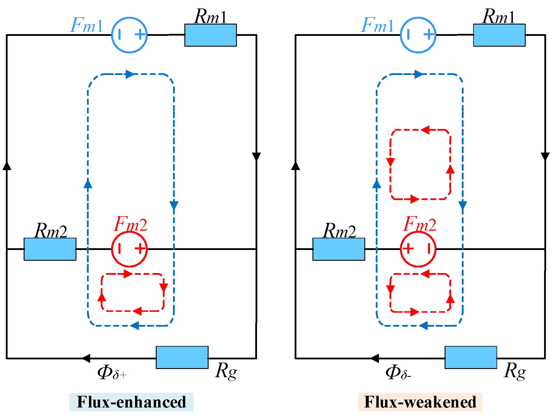
In order to qualitatively reflect the possible effects of the PM arrangements on the flux adjusting range, a simplified equivalent magnetic circuit of PHMMM is established as shown in
Figure 5. The peak air-gap fluxes at the flux-enhanced/weakened states are expressed as [
7].
where
Fm1 and
Fm2 represent the equivalent MMFs of HCF and LCF PMs, respectively. Besides,
Rm1 and
Rm2 are the magnetic reluctances of HCF and LCF PMs, respectively, while
Rg is the air-gap magnetic reluctance.
Moreover, the flux adjusting ratio
αm can be expressed as:
Therefore, by substituting
Φδ+ and
Φδ- into (5), the flux adjusting ratio of the proposed HPMMM can be rewritten as:
Further simplifying the above formula:
where
Hc1 and
Hc2 are the coercive forces of LCF and HCF PMs, respectively;
μr1 and
μr2 are the relative permeability of LCF and HCF PMs, respectively; moreover,
Am1 and
Am2 represent the cross-sectional, respectively.
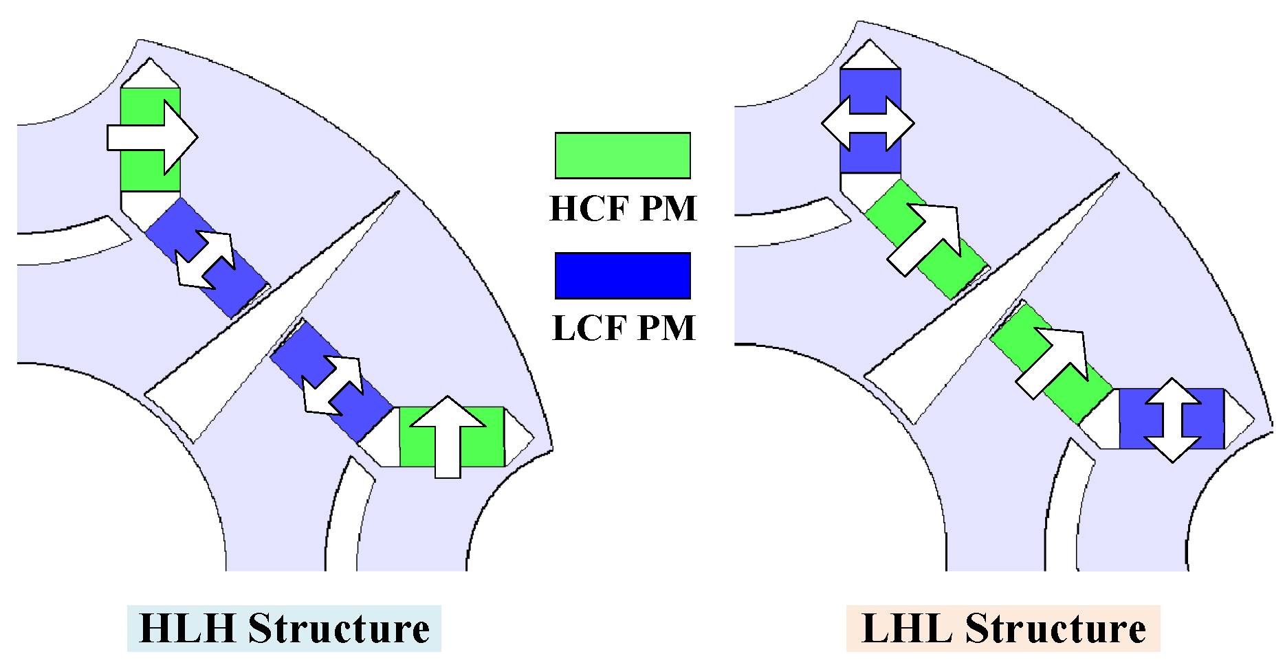
Therefore, it can be seen that the flux adjusting ratio αm of the PHMMM is associated with the ratio of Am1 to Am2. Since the level of the coercive force and remanence of the two types of PMs are different, even if the usage of two kinds of PMs in different structures is the same, the thickness of the two types of PMs is still different due to the geometric limitation of the U-shaped structure, so that the magnetic resistances of the two types of PMs in HLH and LHL structures are unequal. As a result, the peak air-gap fluxes of the HLH and LHL structures are different.
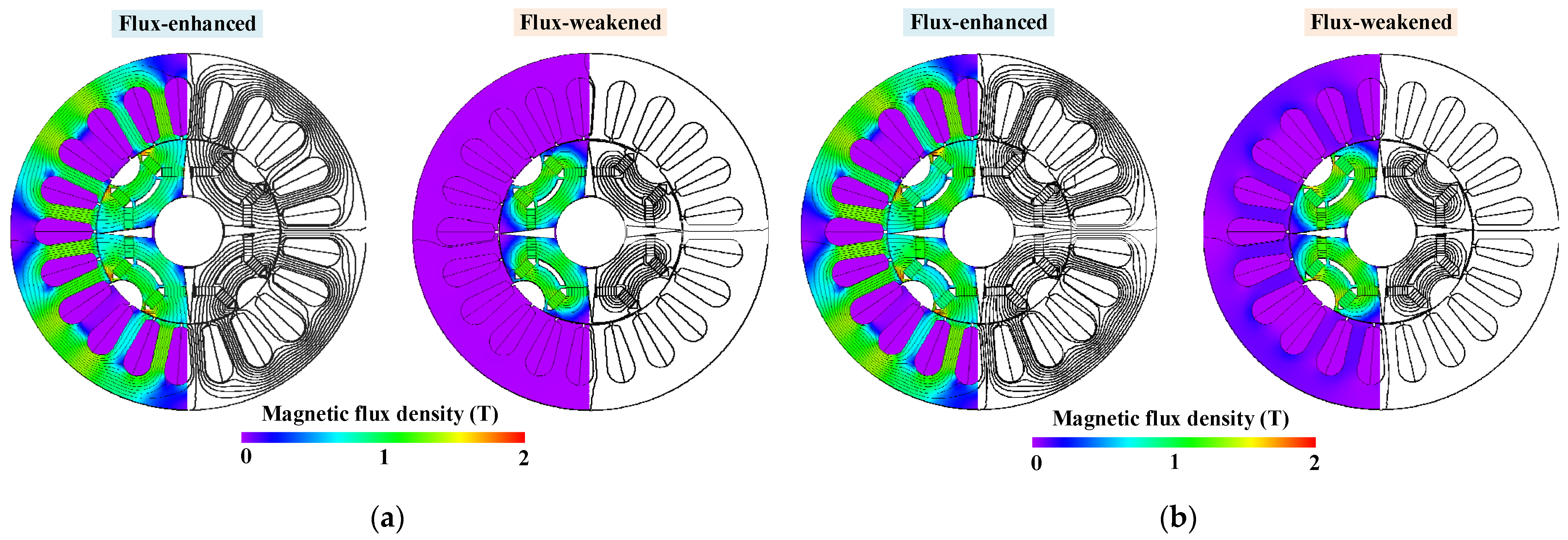
After comparing the cross-sectional areas of LCF and HCF PMs in HLH and LHL structures, the HLH structure owing a wider flux adjusting range on account of the larger ratio of
Am1 to
Am2, which can be also evidenced by the open-circuit field distributions in
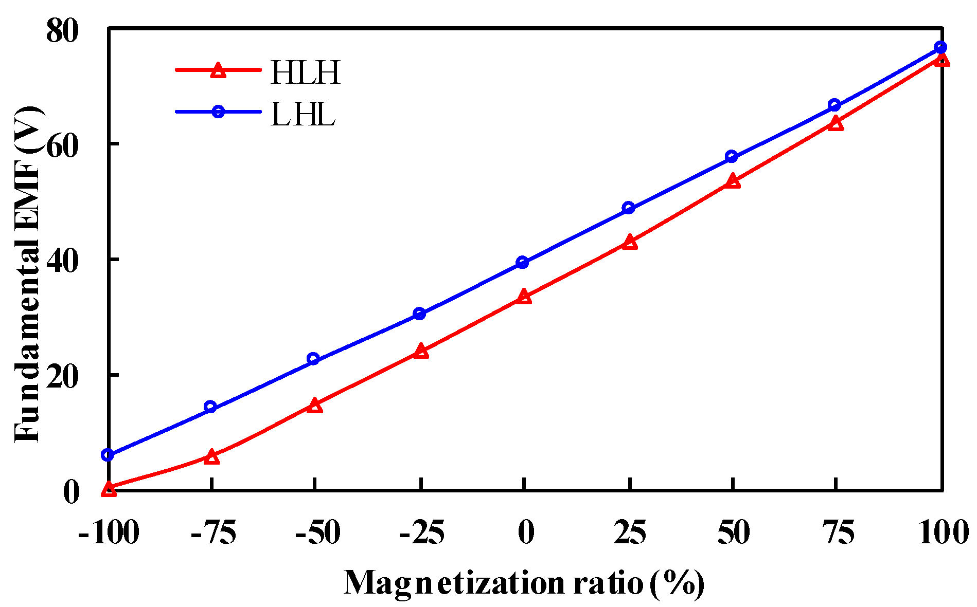
Figure 5. Moreover, the fundamental back EMFs, as functions of the magnetization ratio of LCF PMs, are shown in
Figure 6. It can be observed that the HLH structure shows a slightly wider flux regulation range due to the larger ratio of
Am1 to
Am2, as presented in (7). In addition, the HLH structure shows quite a low fundamental back EMF at the flux-weakened state, resulting in low torque and efficiency. In this case, according to the required flux adjusting range of three times, the MSs “
Kmr = 1” and “
Kmr = −0.5” are chosen for further analysis.
4. Electromagnetic Performance Comparison
The electromagnetic characteristics of the proposed PHMMM with HLH and LHL structures are compared in this Section. The design parameters of the two structures are listed in
Table 1. It should be noted that the two structures share the same stator, HCF and LCF magnet usage, overall dimensions, as well as electric loading in order to ensure the fairness of the comparison.
4.1. Open-Circuit Performance
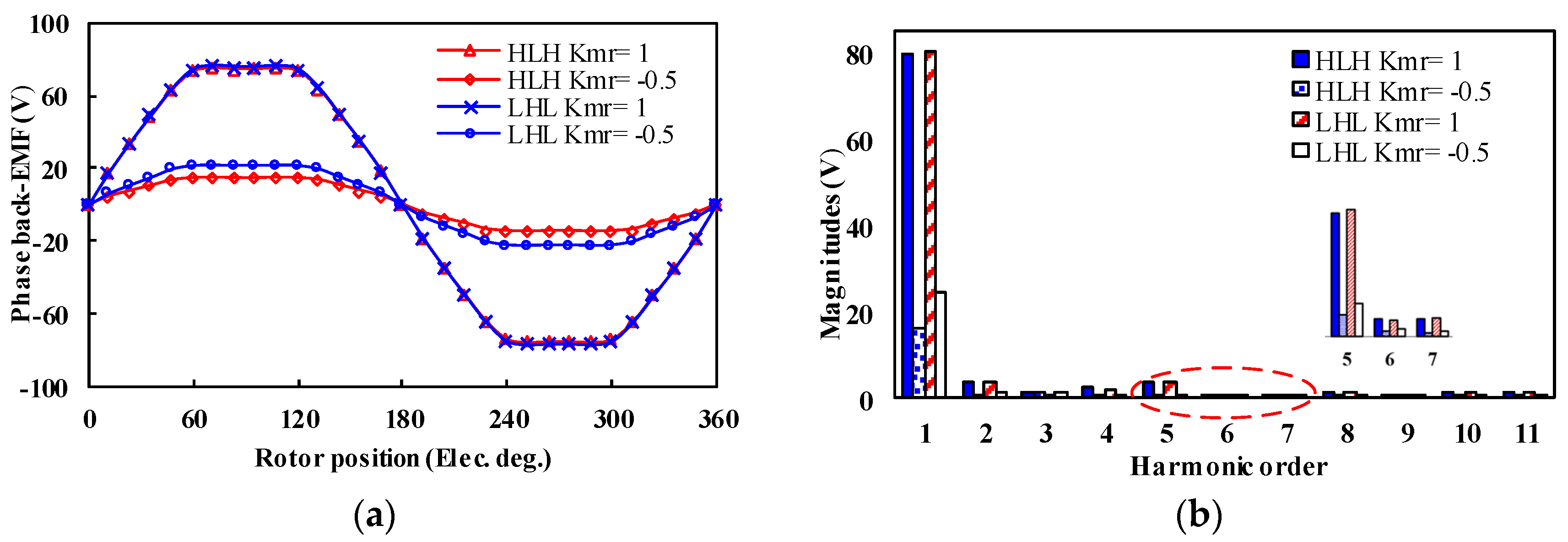
The open-circuit back EMFs and harmonic spectra of the two PHMMMs under different MSs are shown in
Figure 7. It can be seen that the LHL structure shows higher EMF magnitude at both two different MSs.
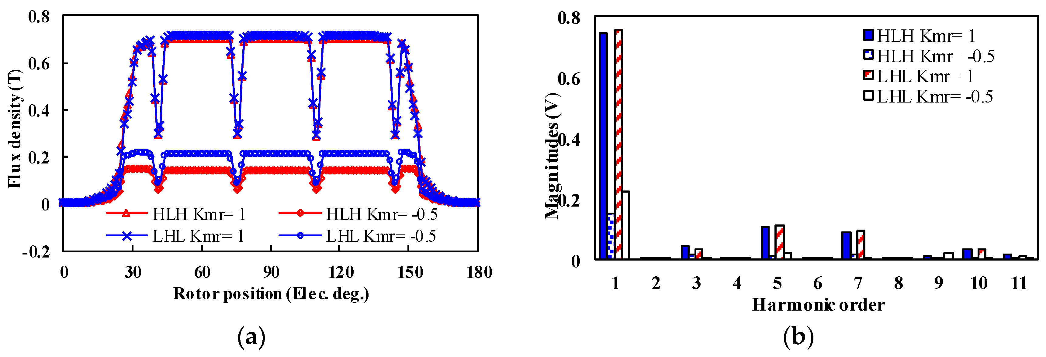
The corresponding air-gap flux density waveforms and harmonic spectra under different MSs are shown in
Figure 8. The LHL structure shows a higher magnitude of flux density under
Kmr = −0.5 state, while the flux density of the LHL structure under
Kmr = 1 state is basically the same as the HLH structure.
4.2. Magnetization Performance
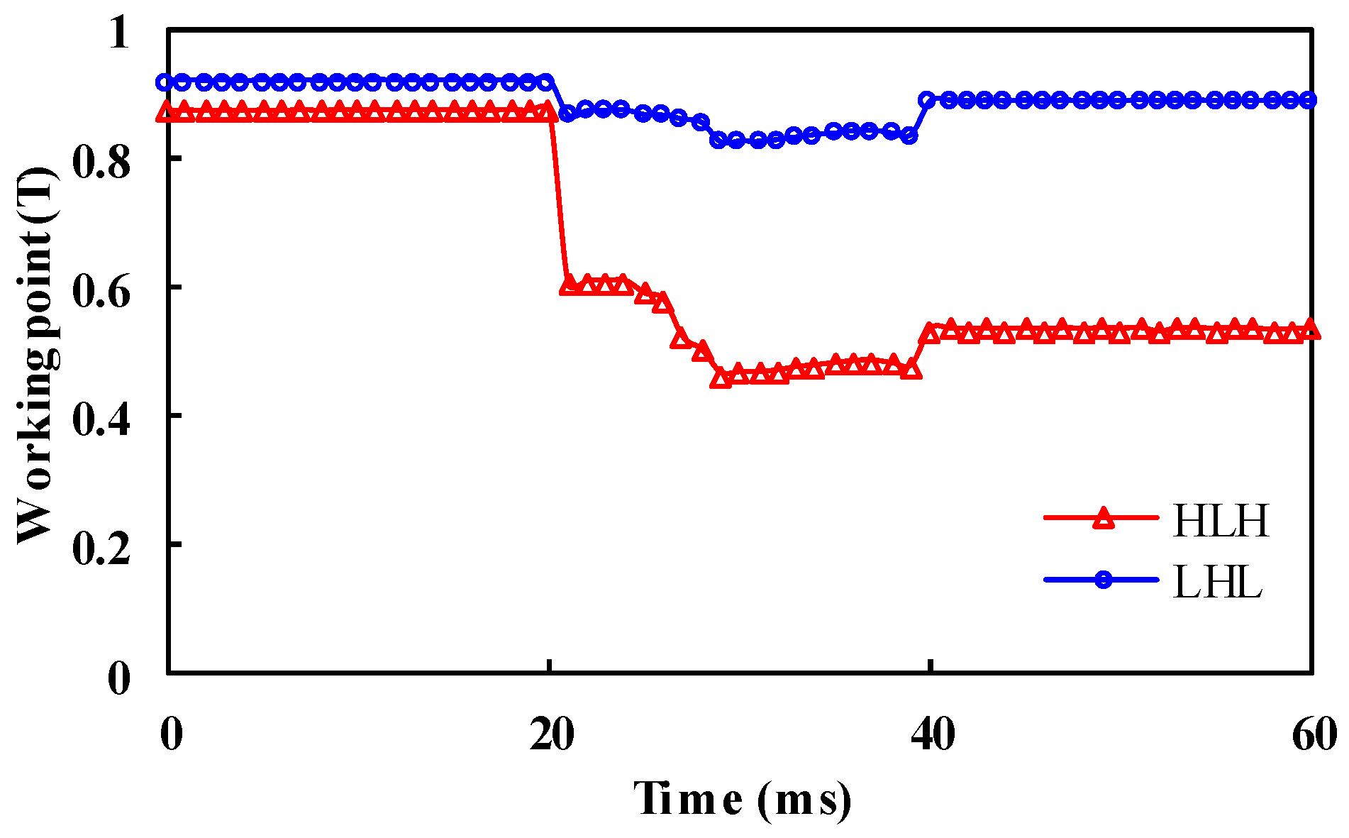
The working point variations of the two PHMMMs before and after applying one electrical period of a
d-axis demagnetizing current pulse of 2A are shown in
Figure 9. The HLH structure is more susceptible to be demagnetized since the LCF PMs in the HLH structure are located closer to the
d-axis centerlines.
Figure 10 and
Figure 11 show the variation of fundamental EMF with the applied
d-axis demagnetizing and remagnetizing current pulse, respectively. The HLH structure requires smaller demagnetizing and remagnetizing current amplitudes. It indicates that the inverter rating of the HLH structure is lower than that of the LHL case, which is beneficial for cost-effective applications.
4.3. Torque Characteristics
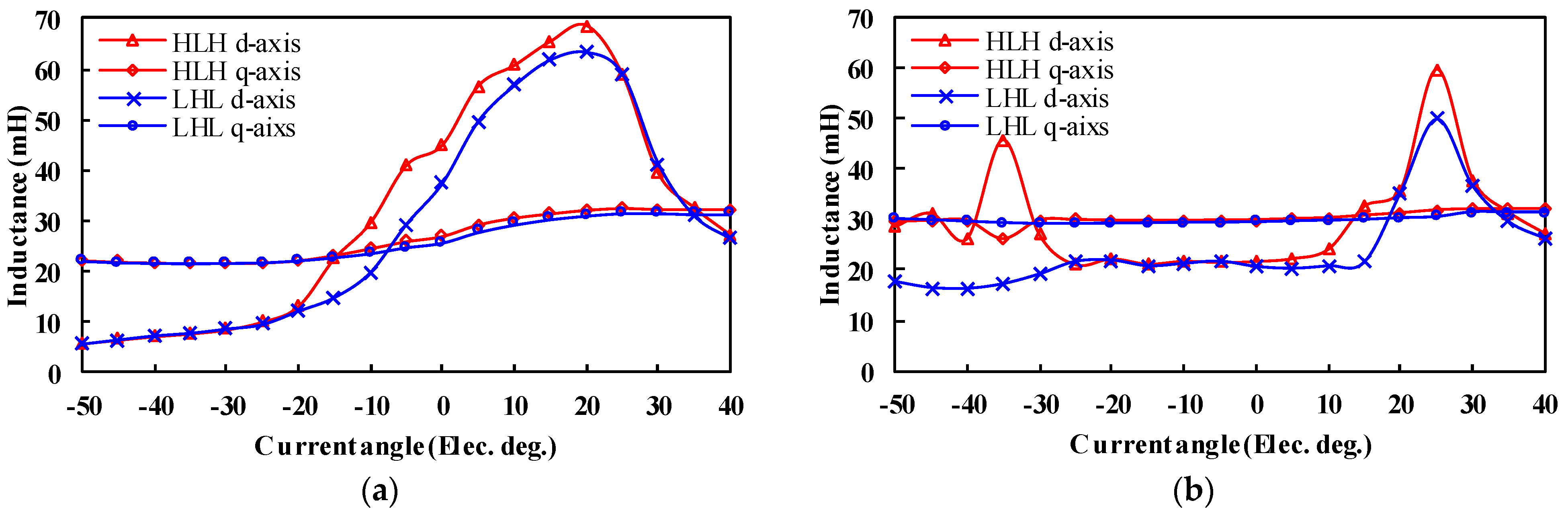
The inductance characteristics of the machine not only affect the flux regulation range but also have an effect on torque capability. For the proposed PHMMMs, the
d/q-axis inductance curves of two types of structures under different current angles are shown in
Figure 12. It should be noted that the current angle is defined as based on the
q axis, which is used to express the phase relationship between the EMF
E0 and the armature current
Ia, that is to say,
q axis refers to the current angle of 0 current degrees, and
d axis corresponds to the current angle of −90 current degrees. It is obvious that the
d-axis inductance experiences a more significant fluctuation than the
q-axis inductance for the two structures due to the design of the
q-axis barriers. For the HLH structure, the flux-intensifying characteristics with “
Ld >
Lq” can be achieved when the current angle is between “−15” and “35” degrees. For the LHL structure, the range will be slightly reduced, between“−5” and “35” degrees.
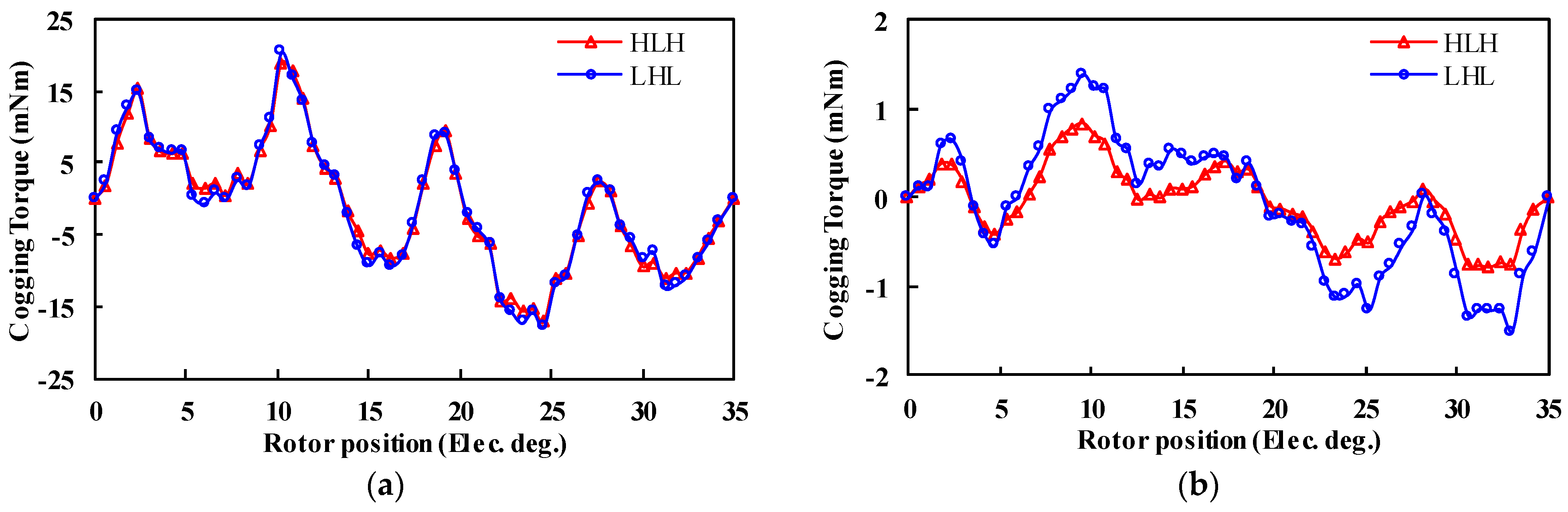
The cogging torque curves under different MSs are shown in
Figure 13. It can be seen that the ripple patterns of the cogging torque of the two cases under the “
Kmr = 1” state are basically the same. However, the LHL structure torque amplitude is relatively higher under the “
Kmr = −0.5” state. This is mainly resulted from larger fifth-order harmonics in the back EMFs, as reflected in
Figure 7b.
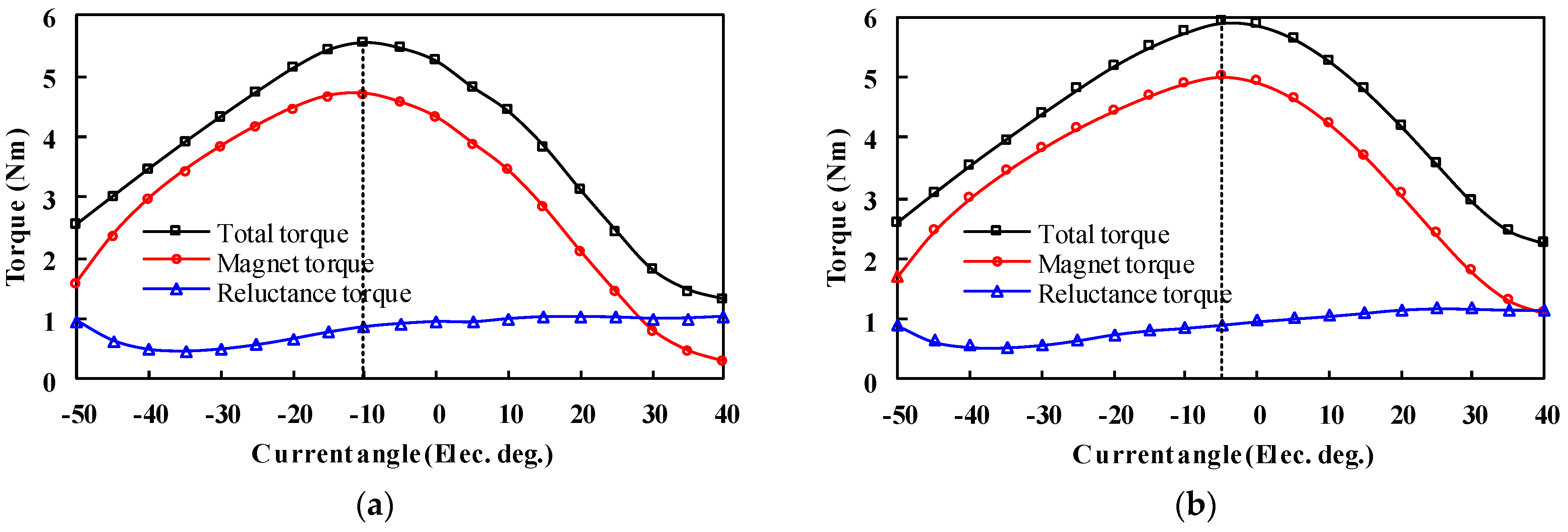
The torque against current angle characteristics under the flux-enhanced state is illustrated in
Figure 14. It can be observed that the maximum torques all occur at a negative current angle of −10 and −5 electrical degrees for the HLH and LHL structures, respectively. Furthermore, the reluctance torque is positive in the selected current angle range, which increases the total torque capability.
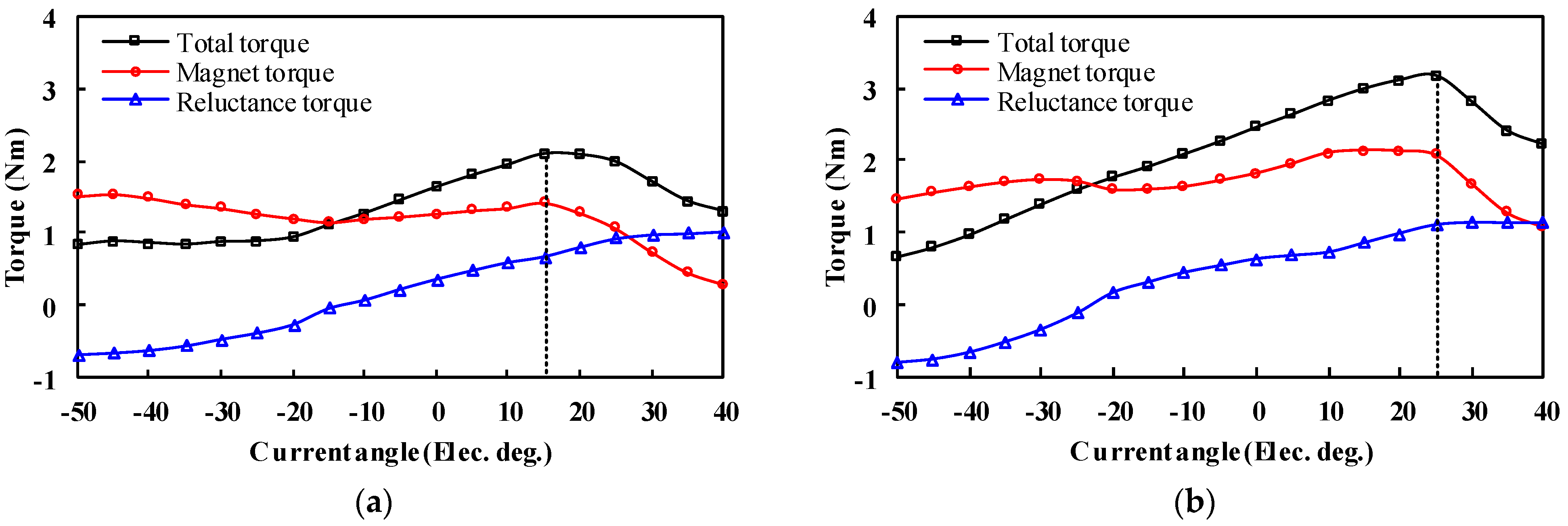
The torque against current angle characteristics under the “
Kmr = −0.5” state is illustrated in
Figure 15. It can be observed that the maximum torques all occur at a positive current angle of 15 and 25 elec. deg. in the two cases, respectively. Due to the low MS of the LCF PMs, the magnet torque decreases significantly compared with that at the flux-enhanced state.
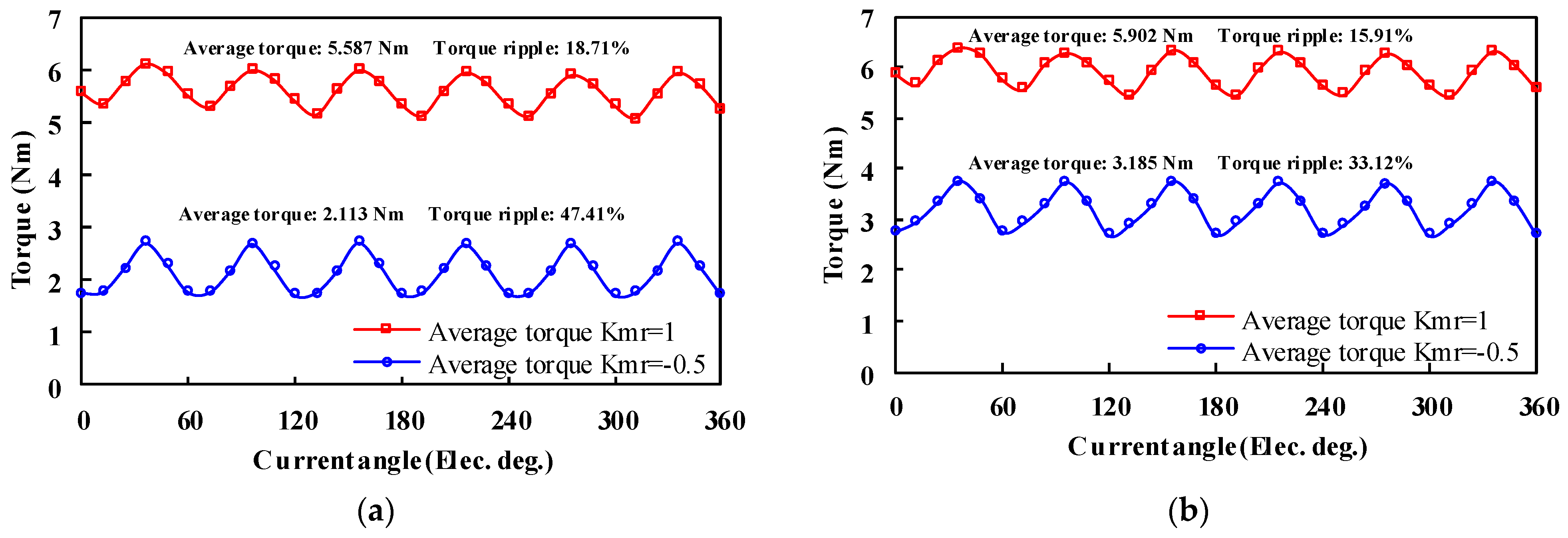
Furthermore, the steady torque waveforms under the maximum torque-per-ampere (MTPA) control with rated current density are shown in
Figure 16. It implies that the LHL structure exhibits higher torque and less torque ripple rate than the HLH counterpart regardless of MS.
4.4. Demagnetization Withstand Capability
The unintentional cross-coupling demagnetization caused by the armature reaction or NdFeB PM field in two PHMMMs should be further examined.
The cross-coupling demagnetization ratio can be defined as [
7,
14]:
where
E1 and
E2 are the fundamental back EMFs before and after applying rated current. The demagnetization ratio DR of the two structures under different loads is calculated, as shown in
Figure 17.
The demagnetization ratios of the LHL structure under different armature currents when Kmr = 1 are higher than those of the HLH structure. Moreover, the unintentional demagnetization will aggravate with larger current amplitude. In addition, both two structures show a small cross-coupling demagnetization ratio under the “Kmr = −0.5” state. This is because the HCF PMs are short-circuited by LCF PMs, leading to a flux loop formed within the rotor core. In this case, the HCF PMs can stabilize the working points of the LCF PMs in turn. It can be summarized that the LHL structure turns out to be more susceptible to the armature reaction, which shows a lower undesired demagnetization withstand capability.
4.5. Efficiency Performance
The five commonly used magnetization states (
Kmr = ±1, ±0.5, 0) of the two motors are simulated, and the comprehensive efficiency map is obtained as shown in
Figure 18. It can be seen that both motors have relatively high comprehensive efficiency.
5. Experimental Verification
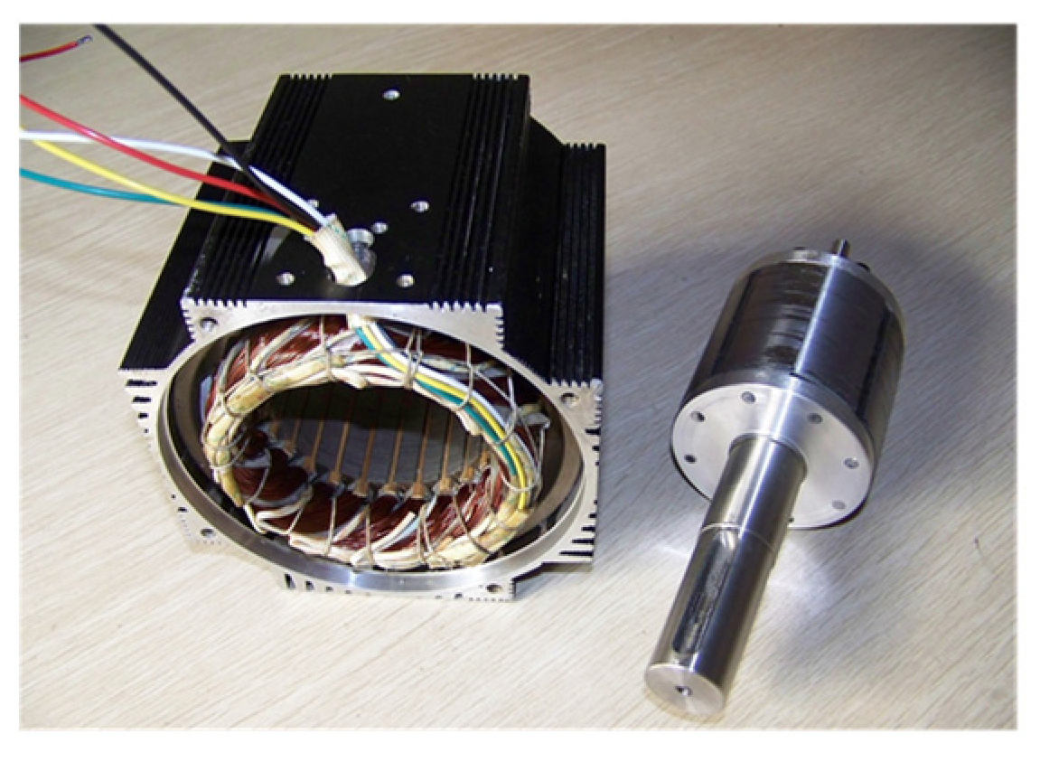
In order to validate the proceeding analyses, an HLH PHMMM is manufactured and tested. The fabricated machine is shown in
Figure 19.
Figure 20 is a schematic diagram of the test platform. The test platform basically includes an adjustable DC power supply, inverter, PC, test prototype, coupling, load machine, and controller. The adjustable DC power supply injects a three-phase current into the inverter to drive the PHMMM for motoring operation. In addition, the PC terminal can use the controller to apply instantaneous
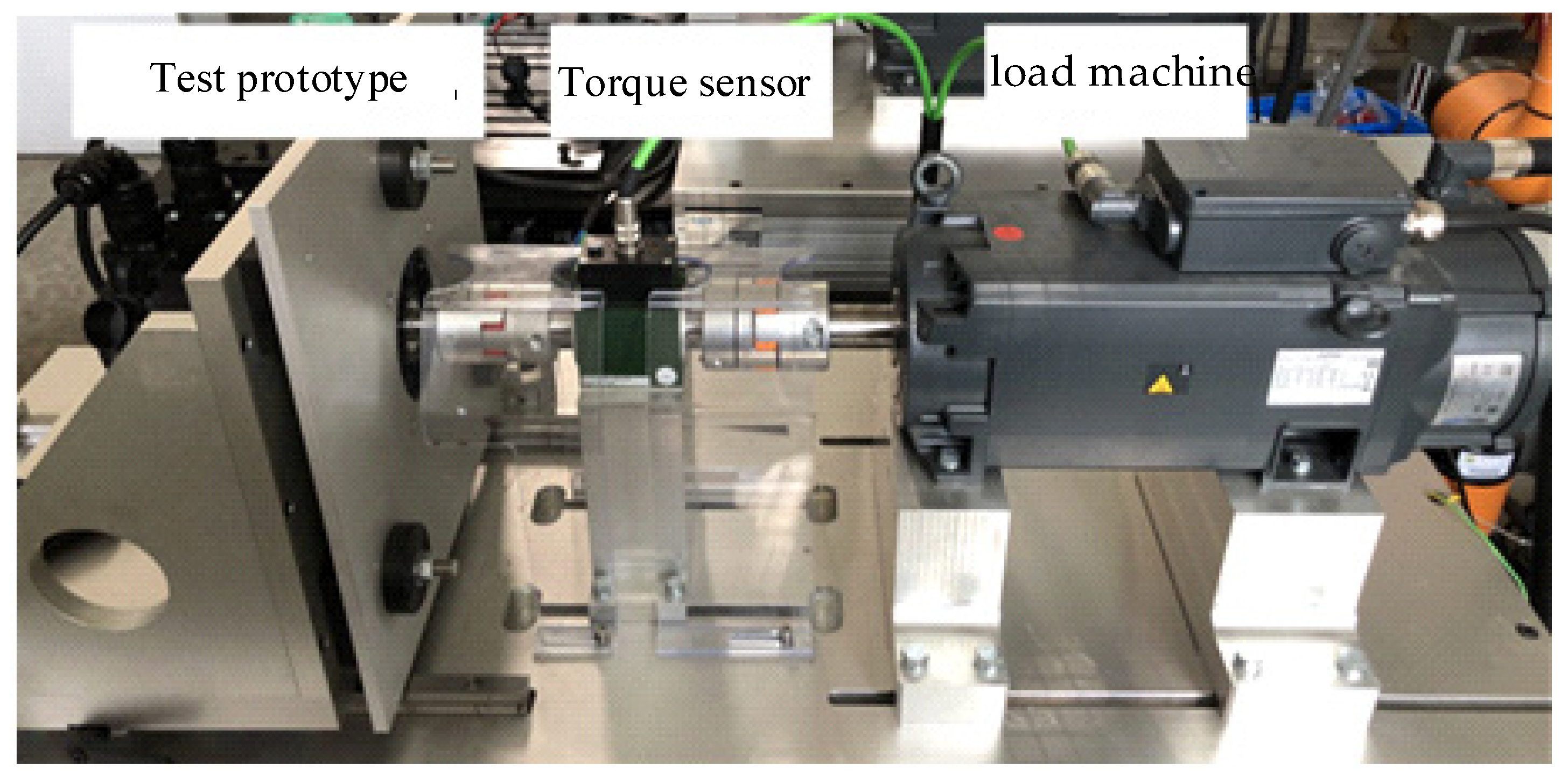
d-axis current pulses to change the MS during the load operation. The prototype drives the load machine to rotate at the same speed through the coupling. At this time, the torque data can be fed back to the PC in real time through the torque sensor to record the relevant data. The actual test platform is shown in
Figure 21.
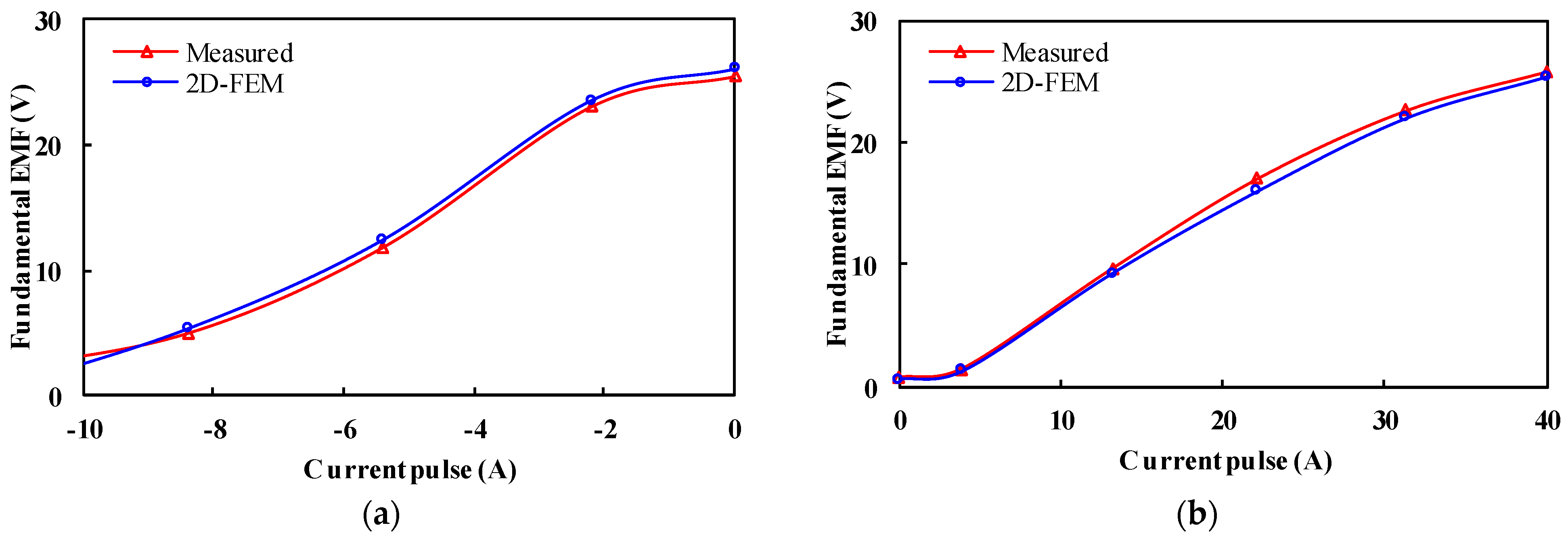
In the finite element simulation, the flux regulation ability is normally reflected by the air-gap flux density. However, in the actual testing process, since the motor’s air-gap flux density cannot be measured directly, it is usually characterized by the no-load back EMF amplitude of the machine under different MSs.
Figure 22 shows the phase fundamental EMF of the manufactured PHMMM with the applied d-axis demagnetizing and remagnetizing current pulses that have been measured and compared with FE-predicted ones. As expected, the 2D-FEM results are consistent with the experimental results. It can be observed that the HLH PHMMM shows a wide flux adjusting range, which confirms the foregoing FEM analyses.
Similar to the simulation process, the experiment was also carried out in two magnetization states, namely the high magnetization state
Kmr = 1 and the low magnetization state
Kmr = −0.5. The torque-speed curves obtained are shown in
Figure 23, and the experimental results can be seen to have high consistency with the simulation.
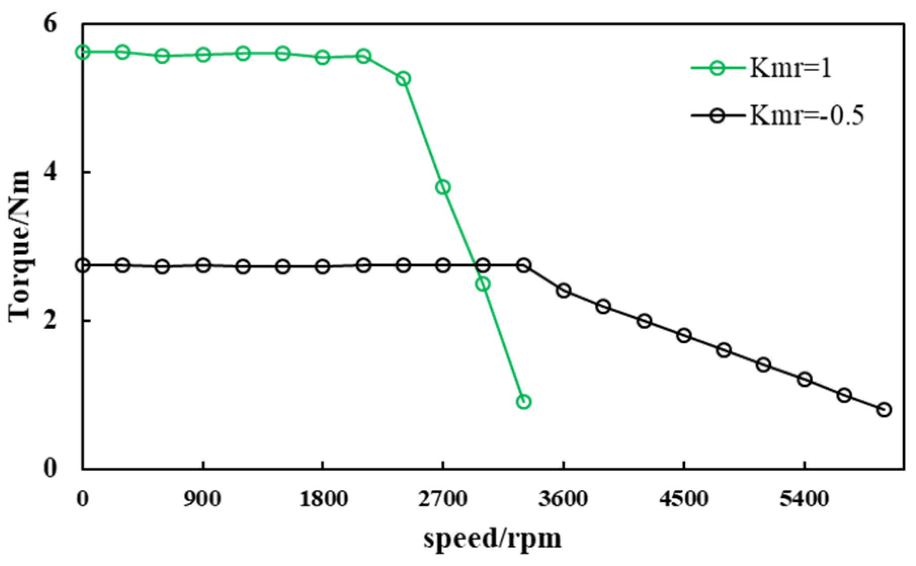
Figure 24 shows the measured torque-speed curves in
Kmr = 1 and
Kmr = −0.5 states. It can be seen that it is similar to the simulation situation. The pulse current demagnetization can be applied to the motor at point
A to effectively broaden the motor operating area. The turning speed is about 3200 rpm.
6. Conclusions
This paper presents a comparative study of the PHMMMs with different PM arrangements. According to the arrangement of the two types of magnets, the PHMMMs can be divided into HLH and LHL structures. The simplified magnetic circuit models of the PHMMMs under different MSs are analyzed, it can be deduced that the HLH structure can obtain a relatively wider flux regulation range. Further, the electromagnetic characteristics of the proposed PHMMM with different PM arrangements are comprehensively compared. It is found that the LHL structure exhibits higher torque density and lower torque ripple than the HLH structure due to its higher peak air-gap flux density and less high-order harmonics. On the other hand, better demagnetization withstands capability, lower magnetizing current, and inverter rating can be observed in the HLH structure. Finally, a PHMMM with an HLH structure is fabricated and tested, which confirms that the HLH structure can achieve a wide flux regulation range. Overall, both PHMMMs have their own merit and demerit and should be selected according to the requirements for the specific applications.


