Article

Cross-Network Information Dissemination in Vehicular Ad hoc Networks (VANETs): Experimental Results from a Smartphone-Based Testbed

1
Guglielmo srl, Strada Parma 31/H, Langhirano 43010, Italy
2
UPMC Sorbonne Universités, LIP6, 4 Place Jussieu, Paris 75005, France
3
Thales Communications & Security SA, 4 Av. des Louvresses, Gennevilliers 92230, France
4
Department of Information Engineering, University of Parma, Viale G.P.Usberti 181/A, Parma 43124, Italy
*
Author to whom correspondence should be addressed.
Future Internet 2013, 5(3), 398-428; https://doi.org/10.3390/fi5030398
Submission received: 1 March 2013 / Revised: 14 June 2013 / Accepted: 5 July 2013 / Published: 5 August 2013
(This article belongs to the Special Issue Vehicular Communications and Networking)

Abstract

:
In this work, we present an innovative approach for effective cross-network information dissemination, with applications to vehicular ad hoc networks (VANETs). The proposed approach, denoted as “Cross-Network Effective Traffic Alert Dissemination” (X-NETAD), leverages on the spontaneous formation of local WiFi (IEEE 802.11b) VANETs, with direct connections between neighboring vehicles, in order to disseminate, very quickly and inexpensively, traffic alerts received from the cellular network. The proposed communication architecture has been implemented on Android smartphones. The obtained experimental results show that an effective cross-network information dissemination service can entirely rely on smartphone-based communications. This paves the way to future Internet architectures, where vehicles will play a key role as information destinations and sources.

1. Introduction

In the last few decades, Intelligent Transportation Systems (ITSs) have attracted the worldwide interest of researchers, automotive companies and governments. ITSs promise to hugely improve the safety, efficiency and sustainability of the transportation system [1]. A key role in ITSs should be played by the so-called Inter-Vehicular Communications (IVCs), a set of new technologies, standards and protocols that should give full networking capabilities to the vehicles. Roughly speaking, it is possible to identify two main features that IVCs should provide to the vehicles: (i) continuous Internet connectivity on a geographical scale; and (ii) fast, but intermittent, local area connectivity to the vehicles and/or other roadside equipment (e.g., traffic lights, pedestrian crossings, guardrails, etc.) positioned in a delimited region. The first kind of connectivity could be provided by leveraging existing network infrastructures (e.g., cellular networks), through any devices present in a vehicle, such as dedicated infotainment devices or general-purpose smartphones and tablets. On the opposite side, the local area connectivity is provided through dedicated On-Board Units (OBUs), implementing a set of Dedicated Short Range Communications (DSRCs) technologies, such as the Institute of Electrical and Electronics Engineers (IEEE) 802.11p [2] or the European Telecommunications Standards Institute (ETSI) Intelligent Transport Systems (ITS)-G5 [3] standards, able to provide a fast transport service in a limited geographical area of interest.
However, several studies show some important weaknesses affecting DSRC technologies, mostly related to reliability and scalability, making their use impractical in low-density networks or in the case of challenging propagation conditions [4]. Furthermore, as of today, DSRCs are facing a significant resistance in reaching the market, because of their strong dependence on the decisions of public administrations and of the lack of a satisfactory business model for selling the OBUs [4,5]. In many circumstances, these limitations can be partially overcome by employing cellular technologies, such as Long Term Evolution (LTE) or some kind of third generation (3G) technology, in a complementary manner [6,7]; even in this case, however, the number of vehicles equipped with an embedded 3G/4G transceivers may be scarce. For these reasons, the general consensus indicates personal devices, such as smartphones and tablets, as key players in developing future ITS solutions. In fact, smartphones are gaining more and more popularity, and nowadays, we may assume that, with extremely high probability, there is (at least) one of these devices inside each vehicle. This new class of personal device is typically equipped with a dual interface, for cellular (typically 3G or LTE networks) and WiFi networks and, therefore, should ideally be able to provide both continuous Internet connectivity and sporadic local connectivity. Obviously, the performance of vehicular communications based on smartphones is not comparable to communications based on dedicated hardware, but in certain conditions, they can offer a satisfying performance level [8]. For all these reasons, it is reasonable to expect that next generation ITSs systems will be based on a heterogeneous mix of hardware (OBUs and smartphones) and communication technologies (DSRCs, WiFi, 3G/4G), as proposed recently in [9,10].
In this work, starting from the results of [10], we further investigate this kind of heterogeneous architecture, by implementing a smartphone-based service for real-time traffic information dissemination. More specifically, we describe the innovative cross-network approach for effective information dissemination in vehicular environments, proposed in the 2011–2012 Italy-Israel “Cross-Network Effective Traffic Alerts Dissemination” (X-NETAD) project [11]. As pointed out in [10], the goal of the X-NETAD project was the design and implementation of low cost, efficient and ubiquitous traffic alerts dissemination to drivers. In particular, it envisions the formation of ephemeral local VANETs, formed by one “primary” vehicle surrounded by “secondary” vehicles. The former vehicle acts as a gateway for traffic alerts coming from a 3G/4G network, which are broadcast to the latter vehicles by means of WiFi broadcast communications. As aforementioned, the peculiar feature of X-NETAD consists in being entirely based on smartphones, without the need for dedicated OBUs. However, it is possible to easily extend the X-NETAD architecture in order to exploit the presence of dedicated OBUs within the targeted vehicles.
While our previous work [10] aimed at presenting the “big picture” of the X-NETAD architecture without disclosing any specific implementation detail, in this manuscript, a comprehensive overview of the main research and scientific aspects of the X-NETAD project is provided. To summarize, the goal of this manuscript is twofold:
  • to provide an in-deep description of the X-NETAD architecture and its implementation on a VANET formed by an Android smartphone;
  • to present the experimental results, obtained by implementing X-NETAD on a testbed of commercial off-the-shelf (COTS) Android smartphones, with no high-end requirements, shedding light on the strengths and weaknesses of the proposed architecture.
This paper is structured as follows. In Section 2, we discuss related works on multihop broadcast protocols and VANET applications based on smartphones. In Section 3, the principle design behind X-NETAD is presented. The details of the dissemination protocol and its implementation on the Android platform are provided in Section 4. The experimental results are illustrated in Section 5. Finally, conclusions are drawn in Section 6.

2. Related Works

Historically, real-time traffic monitoring and congestion-detection systems relied on police reports or dedicated road sensors (e.g., buried inductive loops, active infrared sensors, cameras and radars). In recent years, the widespread diffusion of cellular communications has enabled the design of traffic estimation techniques based on data provided by cellular operators. Typically, cellular networks are used as a source of anonymous geo-referenced raw data, stored and processed in a remote data center in order to extract information on the traffic intensity. Relevant examples of this approach are: (i) the TrafficSense system developed by Cellint Traffic Solutions Ltd [12]; and (ii) the Localizing and Handling Network Event Systems (LocHNESs) platform developed by Telecom Italia, which allows a real-time evaluation of urban dynamics based on the anonymous monitoring of mobile cellular networks [13]. An alternative approach consists in using the smartphones themselves to build distributed location-based services (LBSs), through suitable distributed algorithms and overlays. Distributed LBSs are a clear example of geo-collaboration services, where active users can efficiently discover and disseminate information about existing services (such as a video stream from a webcam, storage volunteers and others), geo-referenced objects and information (e.g., positions of gasoline stations, accidents, bad surface conditions, traffic jams). These approaches, combined with mobile phone-based nodes, allow building distributed applications to harvest efficient traffic information, travel time and auxiliary data in the regions of interest. Rybicki et al., with Peers on Wheels [14] and, more recently, with PeerTIS [15], proposed P2P (Peer-to-Peer) architectures, where participating cars are peers organized in a Distributed Hash Table (DHT), to receive and distribute useful information to improve the vehicle travel time using dynamic route guidance. A different P2P approach, called Distributed Geographic Table (DGT), was proposed in [16] and applied to a real smartphone-based Traffic Information System (TIS) scenario in [17]. The DGT is a structured overlay scheme, where each participant can efficiently retrieve node or resource information (data or services) located near any chosen geographic position. In such a system, the responsibility for maintaining information about the positions of active peers is distributed among nodes, for which a change in the set of participants causes a minimal amount of disruption. The overlay is different from other P2P-based localization systems (DHT and tree-based overlays), where geographic information is routed, stored and retrieved among nodes, which are organized according to a structured overlay scheme. The DGT idea is to build up the overlay directly, taking into account the geographic positions of the nodes and any other information required to build a network, where overlay neighbors are also geographic neighbors and no additional messages are needed to obtain the closest neighborhood of a peer. Hybrid vehicular networks, relying also on cellular connectivity, provide a good solution to overcome the coverage limitations of pure-VANET solutions when the vehicle spatial density is low, thus allowing one to reach an increased number of potentially isolated vehicles [4]. Open issues are (i) the data exchange cost over the cellular infrastructure and (ii) the latency of data delivery, which is higher than the pure-VANET approach. Therefore, cellular network-based distributed architectures are not suitable for short-range safety-driving applications, but could be efficiently applied in scenarios where (i) latency is not an issue and (ii) the distance from the event or generic geo-localized information is sufficient to guarantee proper data dissemination.
Regardless of the origin of the information, the issue of real-time dissemination of this information to the interested vehicles is still an open problem. In recent years, many broadcast protocols for VANETs have been proposed by the research community. In [18], one can find a possible classification of broadcast protocols. In [19], the authors focus, from a theoretical perspective, on efficient broadcasting for mobile ad hoc networks. Position-based broadcast protocols (see [20] and references therein) exploit the knowledge of some geographical characteristics of the network, to improve the retransmission efficiency. For example, the Emergency Message Dissemination for Vehicular environments (EMDV) protocol achieves remarkable performance exploiting pure geographical information and information on the local network topology [21]. The major drawback shared by all position-based protocols, however, is the need for information on the network topology and the geographical characteristics of the environment where the nodes are located [21]. Since collecting this information may be very difficult, several alternative broadcasting protocols have been recently proposed with the goal of achieving the same performance level of position-based protocols without the need for major information exchange. The Urban Multihop Broadcast (UMB) [22], the Smart Broadcast (SB) [23] and the Binary Partition Assisted Protocol (BPAB) [24] are good examples of threshold-based protocols, based on the idea of partitioning the transmission range of the source in distinct regions.

3. X-NETAD: The Idea

3.1. The Big Picture

The goal of the X-NETAD project was to design and implement an innovative traffic alerts dissemination system based on a cross-network (cellular and WiFi) software application, installable on dual-interface (UMTS and WiFi) smartphones [11]. An illustrative representation of the envisioned cross-network traffic alert dissemination system is shown in Figure 1. The key idea of the X-NETAD approach is that of leveraging on the spontaneous formation of WiFi local VANETs, with direct connections between neighboring vehicles, in order to disseminate traffic alerts and GPS location in the VANETs very quickly and inexpensively. It is important to remark that X-NETAD has been conceived of for a unidirectional exchange of information from a centralized data center to mobile vehicles, but it does not allow collecting information from the nodes. (A distributed detection application, based on a similar architecture, is proposed in [25].)
Figure 1. Illustrative Cross-Network Effective Traffic Alert Dissemination (X-NETAD) traffic alerts dissemination scheme.
Futureinternet 05 00398 g001
The X-NETAD system has been designed in such a way that, at any given time, only a small percentage (e.g., 10%) of the vehicles (i.e., the smartphones inside the vehicles) are assumed to be directly connected to the traffic alerts dissemination system through an Internet connection provided by a cellular network. More precisely, the X-NETAD architecture is based on three types of entities: (i) Primary Users (PUs); (ii) Secondary Users (SUs); and (iii) an vehicular ad hoc networks (VANETs) (AS). The AS is in charge of maintaining, filtering and distributing the traffic information, collecting it from a series of third-party providers—in the specific case of the X-NETAD project, the Israeli company, Cellint, had this role. The AS supports the following minimum set of requirements and operations:
  • to provide suitable access interfaces on the Internet;
  • to provide a secure communication channel with the PUs;
  • to possess authentication, authorization and accounting capabilities;
  • to support a basic set of operations to allow the PUs to register to the service and to obtain localized traffic information (of a given geographical area or route) according to a pull-based distribution model.
PUs are privileged users that periodically retrieve the information of interest from the AS, through a 3G (in general, cellular) Internet connection. The SUs obtain information from the PUs via Vehicle 2 Vehicle (V2V) communications according to a push content distribution model (e.g., the PUs periodically disseminate it without any explicit query from the SUs), but they cannot receive the information directly from the AS. To this end, a very efficient broadcast technique for information dissemination in VANETs, denoted as Irresponsible Forwarding (IF), has recently been proposed [26,27]. IF assigns to each vehicle an optimized rebroadcast probability, which takes into account the surrounding vehicle spatial density and can be easily tuned; this guarantees fast information dissemination, even in the presence of high vehicular traffic. According to theoretical and simulative analysis presented in [27], the IF protocol and the related Silencing IF protocol perform better than flooding in terms of latency and efficiency and slightly worse in terms of reliability. Furthermore, the advantages of IF with respect to flooding become more evident as the network congestion increases, as in the case of high average vehicular densities or high network loads. The IF protocol does not require nodes to exchange any additional message and, therefore, could easily replace the legacy flooding protocol that is still used by many Car-2-Car Communications Consortium (C2C-CC) [28] related projects. For instance, the geo-broadcasting protocols defined within the GeoNet project (e.g., GeoBroadcast and TopoBroadcast) rely on the flooding protocol for multihop broadcast communications [29]. We provide additional details on the IF protocol in Subsection 3.3.

3.2. A Push/Pull Dissemination Approach

Generally speaking, the choice between pull-based and push-based approaches should be taken according to four main metric and parameters: (i) the delay affecting the information distribution; (ii) the energy consumption of the device; (iii) the complexity of the client and server applications; and (iv) the unicast or broadcast nature of the communications. In fact, a push-based approach is suitable for broadcast communications, since it allows one to increase the network efficiency. As mentioned in Subsection 3.3.1, in X-NETAD, a hybrid push/pull paradigm is used. In fact, the communications between PUs and SUs use a push-based approach, while the communications between AS and PUs employ a pull-based approach.
A pull-based approach for the AS/PUs communications has been adopted for the following motivations.
  • The communications between AS and PUs are unicast, since (i) 3G networks do not allow broadcast communications and (ii) each PU should receive different information according to its position.
  • The information distributed in X-NETAD are not time-critical, and thus, there is no need to use a push-based approach in order to minimize the delay.
  • The energy consumption is one of the main concerns with mobile applications, and it is well known that a 3G connection has a high energy consumption. By adopting a pull-based approach, the mobile application can schedule the request for traffic updates without the need of keeping a 3G connection active all the time. Moreover, the application can adapt the intervals between consecutive queries according to the behavior of the vehicles. For example, if the vehicle is not moving, there is no need to look for traffic updates. Similarly, if the battery of the smartphone is depleting, the application can decide to reduce the update frequency.
  • A pull-based approach significantly increases the complexity of the server, since it has to cope with a potentially large number of concurrent requests—current techniques, however, should not make this aspect a limitation.
In the case of the PUs/SUs communications, the scenario is totally different. In fact, in this case, the PU transmits the same information to all the SUs and, therefore, it is far more efficient to employ broadcast communications instead of a series of unicast communications. Moreover, in VANETs, the nodes cannot turn off their radio interfaces in order to save energy, because of the following critical issues that affect VANETs: (i) short-lived connections; (ii) highly dynamic topology; and (iii) harsh channel conditions. This prevents a pull-based approach from leading to significant energy savings.
The above reasons motivate the decision for adopting a push-based paradigm, which is also considered in recent works, such as [9].

3.3. The Irresponsible Forwarding (IF) Protocol

In this subsection, we describe the basic idea of the probabilistic dissemination protocol to be used in each VANET to propagate traffic alerts from the primary user (which acts as local VANET source) to all users forming the VANET.

3.3.1. Reference Scenario

Figure 2 shows the linear network topology of reference. We consider a one-dimensional wireless network with N (receiving) nodes, under the assumption that the road’s width is considerably smaller than the transmission range of the vehicles. Each node is uniquely identified by the indices, j { 1 , 2 , , N } . The source node, denoted as node 0, is placed at the left end of the network.
Figure 2. A typical linear network topology of a vehicular ad hoc network (VANET).
Futureinternet 05 00398 g002
The following preliminary assumptions are introduced to derive simple, yet significant, insights. The inter-vehicle spacing is exponentially distributed with mean, 1 / ρ s , where ρ s is the vehicle spatial density (dimension: [veh/m]). In other words, the nodes’ positions are generated according to a one-dimensional Poisson distribution with parameter, ρ s —the validity of this assumption is confirmed by empirical traffic data [30]. Each vehicle has a fixed transmission range, denoted as z (dimension: [m])—the transmission range depends, obviously, on the transmit power that is assumed to be identical for each node. Each vehicle is equipped with a Global Positioning System (GPS) receiver. As a result, each vehicle knows its own position at any given time. The network size (the line length) is set to L (dimension: [m]). For generality, we denote as normalized network size the positive real number, norm L / z , and we observe that ρ s z (dimension: [veh]) represents the average number of vehicles within a transmission range.

3.3.2. Probability Assignment Function
Let us consider a vehicle, at a generic distance, d, from the source node (positioned at the origin of the horizontal axis), within the transmission range of the source. In Figure 2, N z denotes the number of nodes within the transmission range of the source, i.e., d { d 1 , d 2 , , d z } . According to the idea of the IF protocol, the vehicle should rebroadcast the packet only if the probability of finding another vehicle in the consecutive interval of length, z d , is low; otherwise, it should not. More specifically, when a vehicle receives a packet, it compares its position with that of the transmitter and computes its rebroadcast probability as follows:
p = exp ρ s ( z d ) c
where d is the distance between the vehicle and the transmitter and c 1 is a coefficient that can be selected to “shape” the probability of rebroadcasting. The higher the value of c, the higher the probability of rebroadcasting at any position, d. In the particular case with c = 1 , the rebroadcast probability reduces to the probability that there is no vehicle in the interval of length, z d .
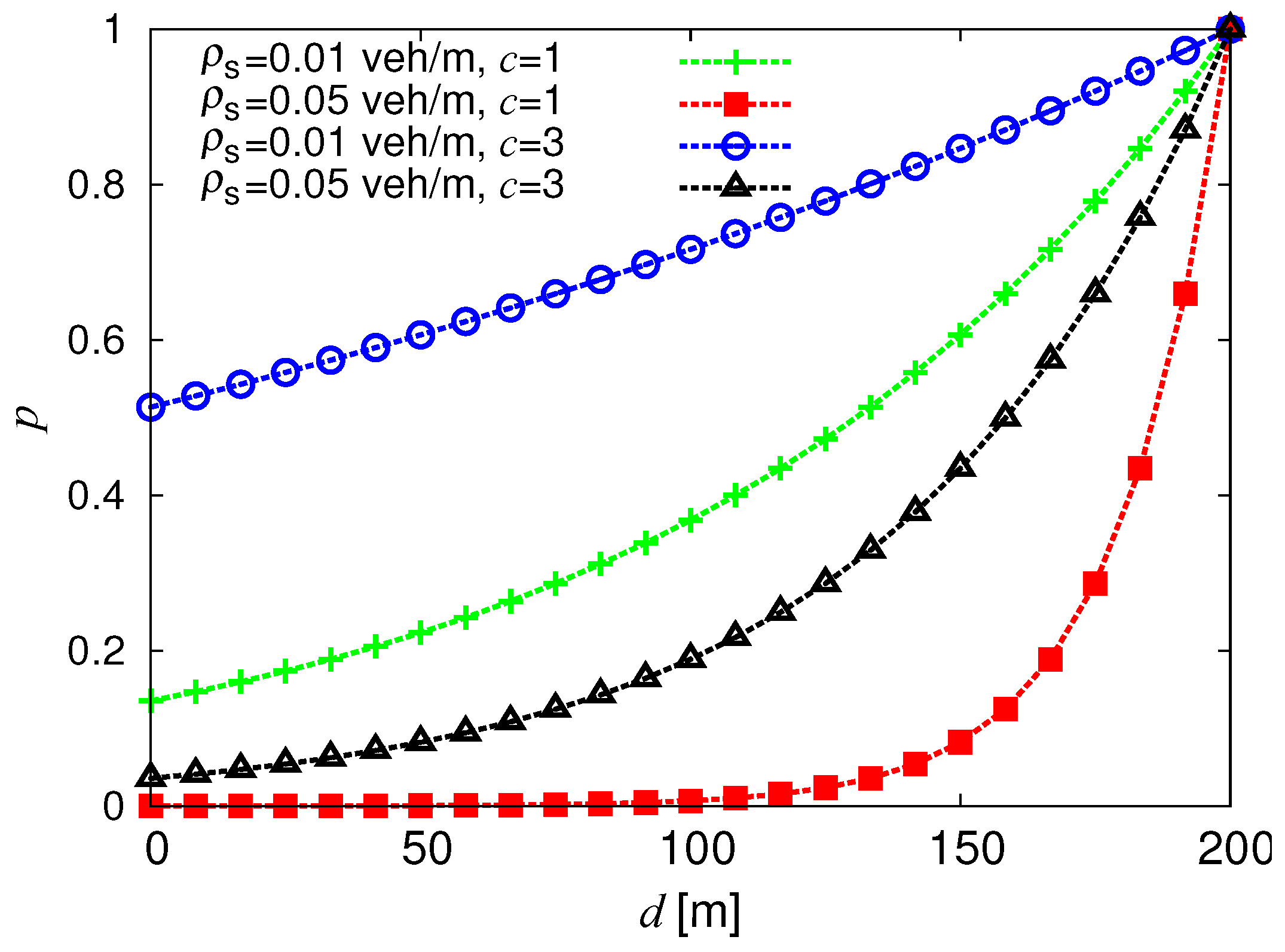
In Figure 3, the rebroadcast probability is shown, as a function of the distance between the receiver and the transmitter, for various values of c and ρ s z .
Figure 3. Rebroadcast probability, as a function of the distance, with z = 200 m, c { 1 , 3 } and ρ s z { 0 . 01 , 0 . 05 } veh/m.
Futureinternet 05 00398 g003
This figure can be interpreted as follows. When d is small, the value of p is also small, because the receiving vehicle is very close to the transmitter, and therefore, it should let the other node take the responsibility of rebroadcasting. When d becomes larger, the value of p becomes larger and approaches one when the node is at the edge of the transmission range. Note that with the probability assignment in Equation (1), the node spatial density is also taken into account. When the network is sparse, the overall rebroadcast probability should be high (e.g., even if the receiving node is relatively close to the transmitter), in order to ensure complete reachability. As observed in Figure 3, when ρ s z decreases from 0.05 veh/m to 0.01 veh/m, the overall forwarding probability also increases. In addition, the coefficient, c, is also effective at shaping the rebroadcast probability, as the overall rebroadcast probability can be increased by increasing the value of c.

3.3.3. IF in IEEE 802.11 Networks

Since communications are broadcast, correct packet reception cannot be acknowledged. Therefore, the packets are never retransmitted and the Contention Window (CW) of the backoff procedure of the Carrier Sense Multiple Access with Collision Avoidance (CSMA/CA) medium access control (MAC) protocol is constant and equal to the value specified by the parameter, CW min of the IEEE 802.11 standard [31]. Moreover, it is well known that broadcast communications cannot exploit the Ready-To-Send/Clear-To-Send (RTS/CTS) mechanism foreseen by the IEEE 802.11 standard. Hence, they suffer from the hidden terminal problem, which inevitably reduces the number of packets able to propagate to the farthest reachable node of the network. Note that the Distributed Coordination Function (DCF) mechanism of the IEEE 802.11 standard obviously introduces an additional channel access delay, proportional to the traffic load and to the parameter, CW min , thus increasing the overall delay. We remark that while the traffic load is ineffective in an ideal (collision-free) scenario, in an IEEE 802.11 network scenario, it will have a relevant impact.
According to various simulations studies carried out to characterize the performance of the IF protocol in realistic IEEE 802.11 networks [26,27], our results show that the IF protocol significantly outperforms a simple flooding protocol, in terms of rebroadcast (and energy) savings. The performance improvement brought by the IF protocol is more relevant for high values of the node density and/or of the traffic intensity, since in these conditions, the IF protocol shows a “self-regulatory” capability, keeping the transmission delay short and the number of retransmissions small. In the presence of Nakagami fading, IF becomes very attractive, providing good performance at a low computational cost.

4. Application Design and Implementation

This section proposes an overview on the design and implementation of the X-NETAD system. At first, we explain how the system operates, discussing also some challenges faced during the implementation process. Next, we describe the message exchange in the system, together with a description of the architecture blocks of X-NETAD nodes, focusing on the structural and logical differences between PUs and SUs.

4.1. System Overview and Challenges

The X-NETAD system is a futuristic network architecture conceived for the distribution of valuable traffic alerts to mobile vehicles, taking advantage of both cellular and ad hoc communications. A subset of nodes that form the system (namely, the PUs) should have the ability to simultaneously manage the cellular and the IEEE 802.11 interfaces (the latter being set in ad hoc mode), while the remaining nodes (i.e., the SUs) will only use the IEEE 802.11 interface. The X-NETAD application has been designed to be general enough for various mobile OSs and has been implemented on Android mobile devices.
Like other mobile OSs, Android is natively capable of connecting to IEEE 802.11 networks operating in the infrastructure mode, but it lacks any support for the ad hoc operating mode. However, it is possible to overcome this limitation, since most wireless network adapters inside Android devices are compliant with the full IEEE 802.11 standard and, thus, support the ad hoc mode. This functionality can be exploited running the OS as administrator with super-user rights, using a procedure called rooting and properly configuring the wireless adapter to connect to ad hoc networks using the classic ifconfig Linux command. Furthermore, the access to network interfaces is natively exclusive, i.e., only one between the cellular and the IEEE 802.11 interfaces is active at a time. In X-NETAD, we have introduced suitable software routines that overcome this limitation by properly altering the routing table of the devices, making it a true multi-homed device.
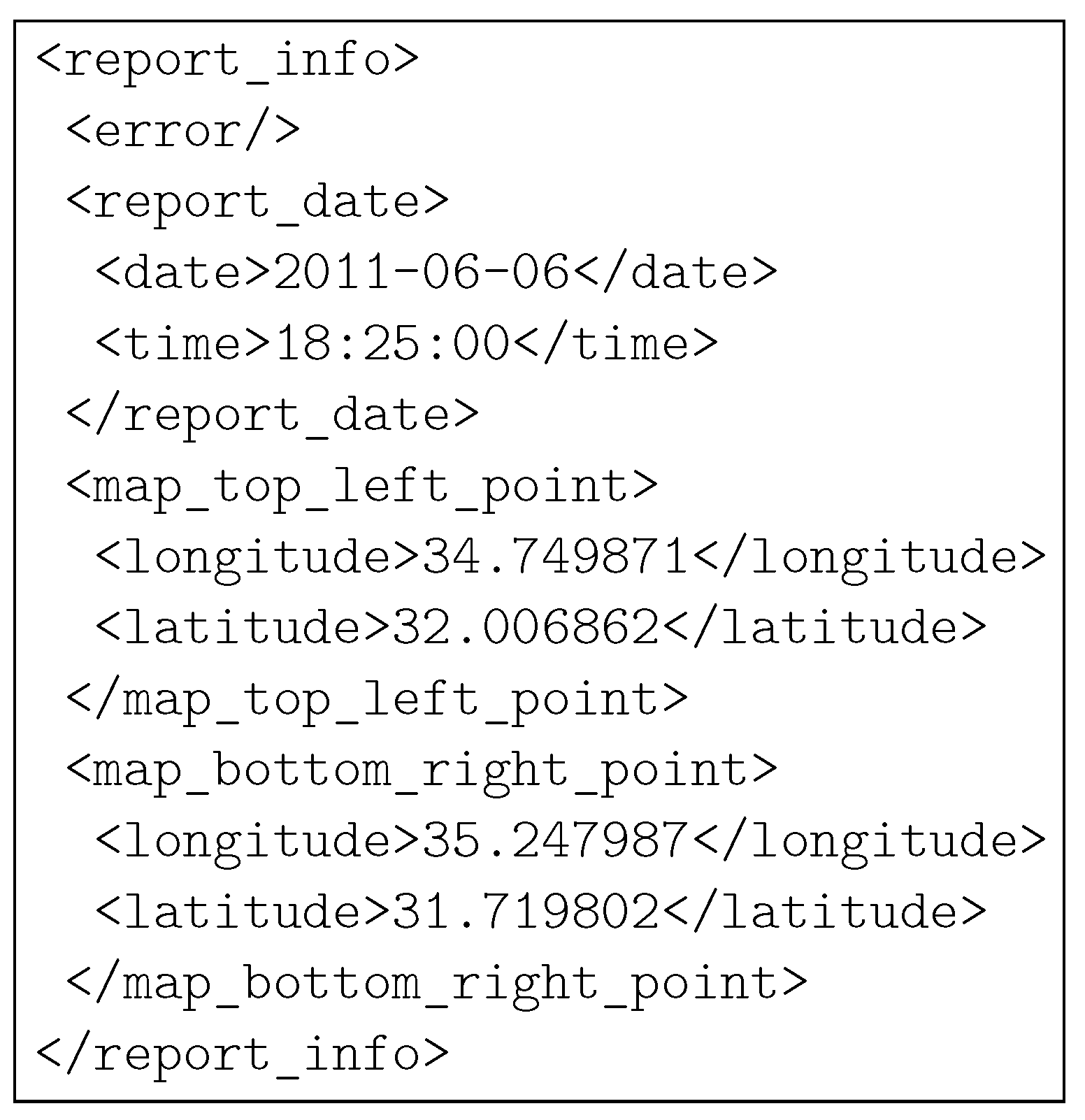
We designed the X-NETAD in order to process and transfer large information amounts. In this way, the information exchanged—at first, between the AS and the PUs and, subsequently, between any PUs and the surrounding SUs—could include multimedia data, such as audio, video and map files. For instance, in our proof-of-concept application, the information issued by the AS is a compressed archive that includes a real-time traffic map in jpg format, an audio file in mp3 format and an XML-formatted document. (In the following, we will refer to the terms, traffic update, archive and information, to the overall traffic information file created by the AS.) The XML document contains information about the traffic update: its date and time of creation, the map’s longitude and latitude coordinates expressed in degrees and, eventually, the information about errors that may have occurred in the network. An example XML-formatted text file is shown in Figure 4. We intentionally decided to focus on “complex” information, rather than on simple text messages, in order to be able to present a rich content to X-NETAD users. In this way, it is possible to inform the driver without distracting his/her eyes from the road, by simply playing the received audio alert on his/her mobile device.
Figure 4. A possible example of XML-formatted document created by the Application Server (AS).
Futureinternet 05 00398 g004
The transmission of this relatively large amount of data (the size of the archive could reach some MB) in the ad hoc domain becomes challenging, due to the limited range of the wireless interfaces and the vehicles’ mobility. In addition, classical phenomena, such as fading, shadowing and the contention-based channel access mechanism employed by the IEEE 802.11 standard, actively contribute to limit the theoretical maximum throughput of the system. In order to reduce the impact of the problems mentioned above, the compressed archive received by a PU through the cellular interface is not directly transmitted to SUs, but, instead, is split in many small pieces that are disseminated independently.
On the basis of an analysis of a VANET’s peculiar characteristics, such as high node mobility and limited transmission range, we adopted a broadcast (starting from a primary node) approach for our system. In X-NETAD, all vehicles act as independent routers and cooperate together, fostering the complete reception of the traffic update. All transmissions in the system are broadcast, in order to reach the largest number of nodes at a time and to avoid any overhead related to routing tables’ update issues. The IF protocol controls message rebroadcasting, guaranteeing an efficient network-wide data dissemination.

4.2. Message Structure and Dissemination Protocol

4.2.1. Cellular Domain

Updated traffic information is retrieved by PUs via an HTTP GET request sent to the AS through the cellular network—requests may be periodic or triggered by a user. Important parameters, such as the username, the password and the geographical coordinates (latitude and longitude), of the requesting node are included in the GET request by the X-NETAD client. The AS needs the usernames and passwords of the nodes for authentication purposes. The traffic information provided by the AS is geographically relevant, taking advantage of the PUs’ coordinates. If the authentication information provided is correct, the AS replies to PUs by sending the archive containing the local traffic update.

4.2.2. Ad Hoc Domain

As previously mentioned, we designed the X-NETAD system in order to be able to disseminate a (relatively) large content, adapting to the constraints imposed by the VANET scenario. The strategy we adopted to enforce this feature split the archive that comes from the cellular network into smaller pieces, called chunks, which are disseminated independently. Chunks are small data units of fixed size, exchanged during a single contact of limited duration with high probability. If a chunk is only partially received from a node (e.g., due to a connection breakdown), it is discarded. If, on the one hand, splitting the traffic update into several chunks allows nodes to receive parts of the same traffic update from different nodes, on the other hand, this adds complexity to the system, because nodes should be able to recognize which chunks are missing and, if needed, should request them back.
The system behavior can be described as follows. The original traffic update received from the AS through the cellular network is divided in several chunks by the PU, and every chunk is packed into different data-bearing messages denoted as DATA. A DATA message contains the actual data chunk and the chunk index; this index is crucial, because it allows the receiving of nodes to identify which part of the update they are receiving. In fact, each SU maintains a local bit-vector in its memory, whose length equals the total number of chunks of the current traffic update, where the i-th bit indicates whether the i-th chunk is missing (bit set to zero) or present (bit set to one). After each DATA message is received by an SU, the local bit-vector is correspondingly updated. The payload of any DATA message, related to the same traffic update, has a fixed size, apart for the last chunk. This size depends on the dimension of the original traffic update and on the number of chunks in which it is divided. The chunk size is an important parameter that significantly affects the system performance. With large chunks, there is the risk of performance degradation when partially received chunks are discarded by the network interface. The choice of small chunks reduces the amount of wasted reception, but it also increases the overhead. It is worth recalling that before being able to decode a traffic update, a node must receive all the DATA messages associated with it. DATA messages are propagated and replicated network-wide using the IF protocol, thus providing redundancy in the system.
Whenever a PU receives a new traffic update from the AS using the cellular network, it should disseminate this information to SUs located in the ad hoc domain. To make SUs aware of the existence of a new traffic update, allowing them to create a local bit-vector for the update, the PU issues an ADVERTISE message. This message contains information on the update, such as its size and the number of chunks in which it is divided. Once a SU receives a new ADVERTISE message, it creates a new bit-vector for the update and becomes ready to receive its flux of DATA messages. Since, without this message, a SU cannot store the subsequent chunks of data, the goal is to provide a fast and reliable dissemination of the ADVERTISE message all over the network using the IF protocol. This message is also periodically broadcast by PUs, allowing SUs, which join the network later, to get the traffic update.
Because of the probabilistic nature of IF and of the underlying contention mechanism, there still exists the opportunity that messages may be lost due to noise bursts on wireless channels or to message collisions. A simple solution to recover from packet losses is to use a feedback loop. To minimize the total number of packets sent in the network and, thus, to prevent congestion and additional collisions, SUs ask periodically for missing chunks using a REQUEST message. The payload of the REQUEST message is a bit-vector representing the reception status for each chunk. Periodically, each SU examines its local bit-vector, and missing chunks are requested back (in broadcast) to neighbors, using the REQUEST message. Regardless of the nature of a node (PU or SU), upon the reception of a REQUEST message, a node checks its local bit-vector and tries to satisfy, if possible, the request. As opposed to other X-NETAD messages, the REQUEST message is intrinsically single hop and is never re-broadcast in order to maximize the reception probability of missing chunks and to avoid repeatedly saturating the network with useless packets. A node replies to a REQUEST message with one or more DATA messages if the requested chunks are locally available and according to a probabilistic function related to its distance from the sender. This replying probability is expressed accordingly to the following “reverse” IF probability assignment function:
p = exp ρ s d c
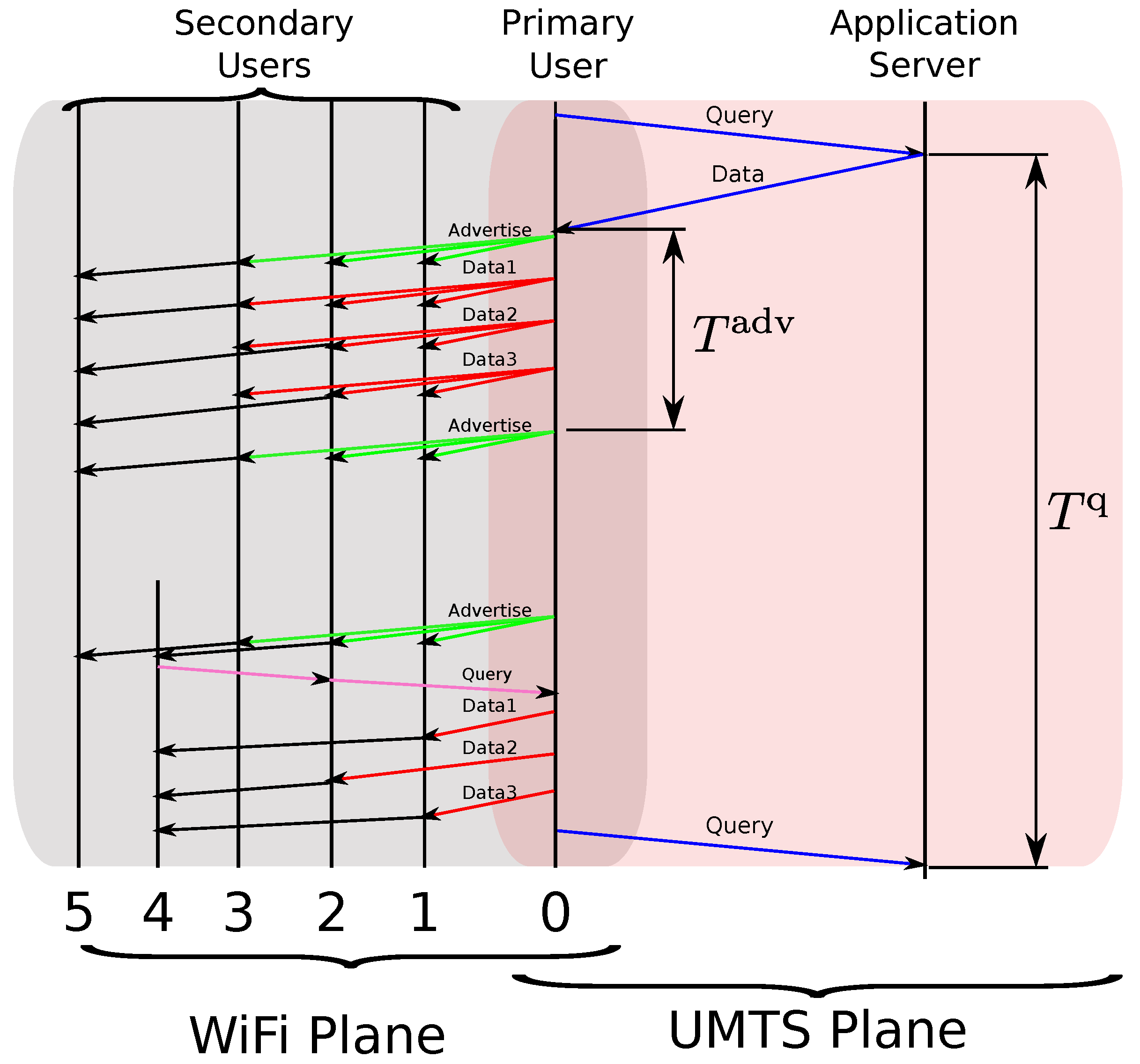
where ρ s is the spatial density of vehicles in the VANET; d is the distance between transmitter and receiver; and c is a shaping coefficient. Clearly, this function assigns a higher replying probability to nodes that are located near to the original sender, namely those with a smaller packet loss probability. It is important to observe that the replied (e.g., transmitted upon reception of a REQUEST message) DATA messages are disseminated using the IF protocol. In Figure 5, an illustrative representation of the X-NETAD session of message exchange between the AS, one PU and a multitude of SUs is shown.
Figure 5. Temporal diagram of a generic X-NETAD message flow.
Futureinternet 05 00398 g005

4.3. System Architecture

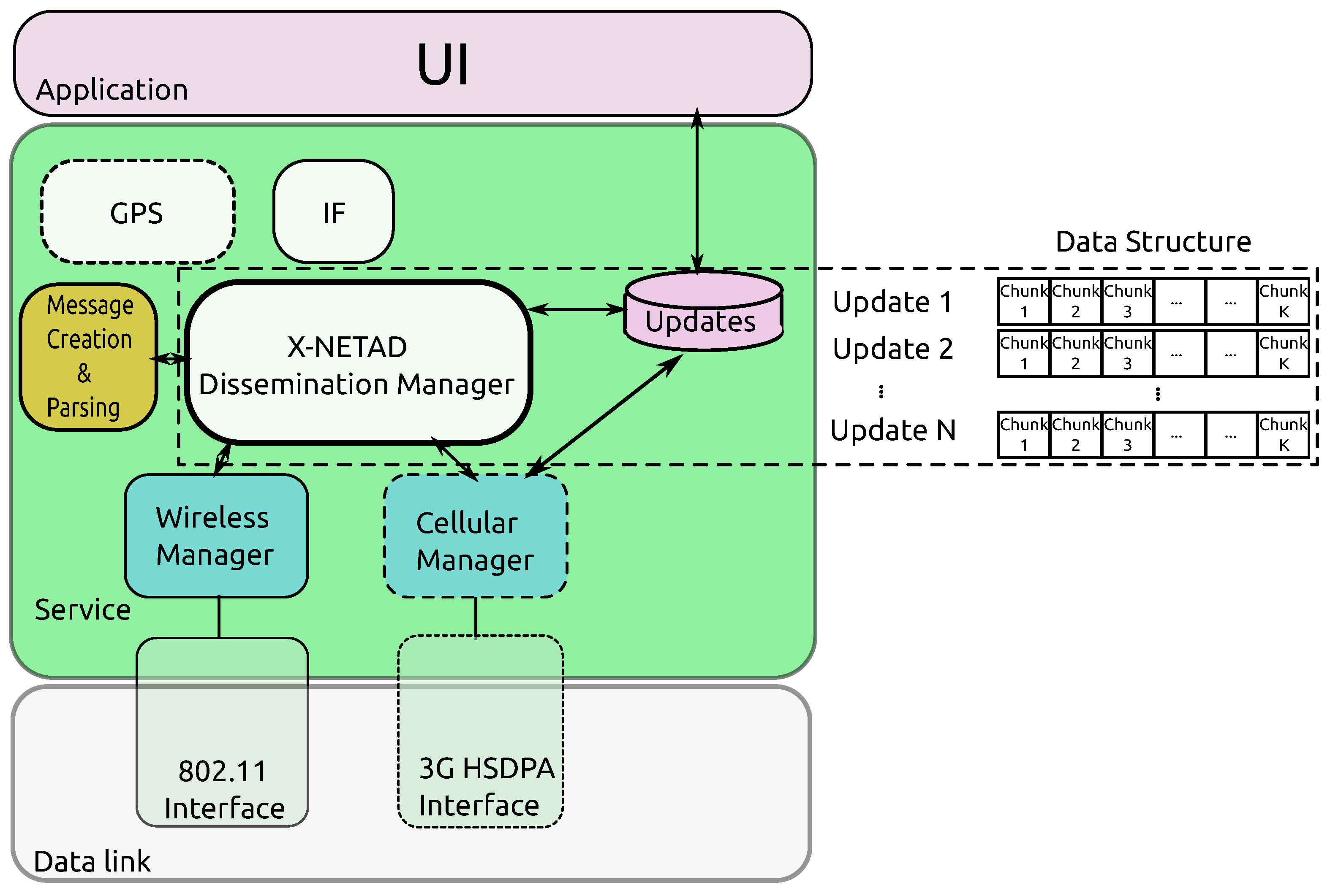
In Figure 6, a general illustration of the X-NETAD mobile application is shown. Traffic updates are transferred from the AS to the PUs via the cellular network. Content can also be exchanged directly between PUs and SUs when they are within the communication range of one another. In this work, we focus primarily on the system design with respect to content diffusion between nodes in the ad hoc domain.
The architectural differences between the two distinct types of nodes are restricted to the ability of PUs to connect to a cellular network, in order to communicate with the AS. For this reason, a PU’s architecture exhibits a Cellular Manager block—drawn with a dotted line, to remark on its presence only at PUs—that is in charge of the communications taking place with the AS (see Section 4.2.1.) using the cellular interface. The Wireless Manager block, on the other hand, is present at any node, because it drives the IEEE 802.11 interface and is fundamental in the dissemination process taking place in the ad hoc domain. The X-NETAD Dissemination Manager is the key component of the whole system, due to the fact that it is in charge of the logical system management. If a new update is received from the AS, its content is stored locally, split in smaller chunks and the dissemination process is started. Upon the reception of an X-NETAD message on the IEEE 802.11 interface, the Dissemination Manager performs all the actions required to handle the message (see Section 4.2.2.). For example, when the system receives a DATA message, the Dissemination Manager checks if the received chunk is missing, updates (if required) its local bit-vector and, with the help of the IF and the GPS blocks, decides if the message has to be re-broadcast.
Figure 6. System architecture of an X-NETAD node.
Futureinternet 05 00398 g006
When a new traffic update is available, regardless of whether it was retrieved from the cellular or the IEEE 802.11 interface, it is presented to the user through the User Interface (UI) application. If the update contains an audio message, then this message is played, and the additional content is presented according to the user’s preferences.

5. Experimental Results

In this section, we analyze the experimental results in different environments, obtained with a test-bed composed by four LG Optimus One (P-500) smartphones and a Samsung Galaxy Tab tablet, all equipped with release 2.3.3 of the Android OS. The experimental campaign is conducted in three different phases. In the first phase, we preliminarily investigate the relationship between the Packet Error Rate (PER) and a couple of physical parameters, namely, the IEEE 802.11 transmission data rate (in Subsection 5.2.1) and the inter-node distance (in Subsection 5.2.2). In the second phase, described in Subsection 5.3, we evaluate the performance of the X-NETAD application in a couple of ideal static scenarios, where the nodes are fixed. In the third phase, described in Subsection 5.4, we consider a more realistic scenario, where the devices are positioned within distinct vehicles moving along a predefined path. In the second and third phases, the behavior of the X-NETAD application is characterized according to the performance metrics introduced in Subsection 5.1. Finally, in Subsection 5.5, the obtained results are discussed.

5.1. Metrics of Interest

Depending on the nature of the metric of interest, we have characterized it (statistically) in terms of either average value, Probability Mass Function (PMF) or Cumulative Distribution Function (CDF). The performance metrics considered in our experimental campaign can be summarized as follows.
  • The number of DATA messages retransmitted at each SU—the ratio between this quantity and the total number of transmitted packets is correlated to the Probability Assignment Function (PAF) of the IF protocol defined in Equation (1).
  • The PMF of the hop index at which the DATA messages are received. This indicator is strictly related to the distance between a PU and an SU.
  • The number of missing DATA messages, before the first REQUEST message. This metric is a coarse indicator of the wireless channel quality. In ideal conditions, the PMF should concentrate only at zero. However, in realistic conditions, this statement is not valid, due to radio channel interference and fading.
  • The number of DATA messages requested when receiving a REQUEST message. This metric is representative of the “attitude” of a node to receive requests for missing chunks from surrounding nodes.
  • The PMF of the archive reception time. This metric indicates the amount of time it takes to a node to receive all the chunks of the archive sent by the PU.
  • The CDF of the number of DATA messages received before each REQUEST message. This metric is an indicator of the reception status of the traffic update before each round of REQUEST messages.

5.2. Preliminary Results

5.2.1. PER as a Function of the Data Rate

Since the transmission power of IEEE 802.11 compliant transceivers is fixed by the regulatory authorities, the length of an IEEE 802.11 link (i.e., the transmission range of a node) depends only on the receiver sensitivity, which, in turns, is directly related to the selected data rate and modulation. The relationship between sensitivity and the allowed data rates of the IEEE 802.11 standard [31] is summarized in Table 1. Furthermore, the IEEE 802.11 standard does not provide any automatic rate adaptation mechanisms for devices operating in the ad hoc mode. Therefore, the transmission rate must be set during the network initialization phase.
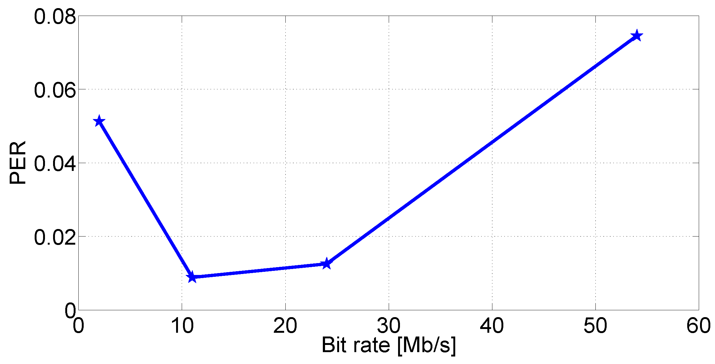
For these reasons, it is interesting to preliminarily investigate the relationship between the transmission rate and the experimental Packet Error Rate (PER) observed in a direct IEEE 802.11 link—this investigation is expedient for performance investigation of the X-NETAD system. In this test, we consider two fixed smartphones, placed at a distance of 15 m: the first inside a car and the second inside a nearby building with large windows. For each value of the data rate, the first smartphone broadcasts 100 streams composed of 1000 User Data Protocol (UDP) packets with an application payload set at 100 bytes. In this setup, the packet losses are mainly caused by: (i) the multipath fading, due to the wireless propagation inside the room and the vehicle; and (ii) the shadowing due to the random movement of persons and vehicle. We consider several transmission data rate values lying in the range, [ 1 , 54 ] Mb/s. From the obtained experimental results, shown in Figure 7, it emerges that, as expected, lowering the data rate can help reduce the PER and extending the transmission range of X-NETAD nodes. However, we found that the minimum experimental PER is obtained when the data rate is set at 11 Mb/s, rather than at 1 Mb/s (i.e., at the lowest possible data rate). This behavior can be explained by the fact that when the data rate is set to 11 Mb/s, the modulation scheme switches to the Direct Sequence Spread Spectrum (DSSS), which is more robust in terms of PER, than the Orthogonal Frequency-Division Multiplexing (OFDM) used at lower rates. Further reduction in data rate does not lead to an additional PER reduction, since the transmission time becomes longer, increasing the likelihood of transmitting during a noise burst and, thus, resulting in a slight PER increase. According to the results obtained in our tests, in the remaining part of this work, we set the transmission rate to 11 Mb/s, in order to have a good trade-off between the transmission range and the PER.
Table 1. Relationship between modulation, data rate and receiver sensitivity defined by the IEEE 802.11 b/g standard (see [31]). DSSS, Direct Sequence Spread Spectrum; BPSK, Binary Phase-Shift Keying; OFDM, Orthogonal Frequency-Division Multiplexing; QPSK, Quadrature Phase-Shift Keying;QAM, Quadrature Amplitude modulation.
Data rate (Mb/s)SchemeModulationRX Sensitivity (dBm)
1DSSSBPSK 89
6OFDMBPSK 82
9OFDMBPSK 81
12OFDMQPSK 79
18OFDMQPSK 77
24OFDM16-QAM 74
36OFDM16-QAM 70
48OFDM64-QAM 66
54OFDM64-QAM 65
Figure 7. Experimental Packet Error Rate (PER) as a function of the data rate, by considering P t = 32   m W and d = 15 m.
Futureinternet 05 00398 g007

5.2.2. PER as a Function of the Distance
Besides the data rate, the distance between communicating nodes in the system has a major impact on the performance of the X-NETAD dissemination protocol. Even if the IF protocol assigns higher rebroadcasting probabilities to the farthest nodes, packet loss probability is an increasing function of the distance. Propagation losses affect all packets, depending on a multitude of factors (e.g., fading, shadowing, absorption, multipath interference, distance). Unlike other factors that are strictly related to the surrounding environment, one can estimate the impact of the distance between sender and receiver nodes through the Friis transmission formula [32]:
P r P t λ d n
where P t represents the transmission power (dimension: [mW]); P r is the received power [dimension: (mW)], λ is the wavelength [dimension: (m)]; d is the distance between receiver and sender [dimension: (m)]; and n is an experimental coefficient that can vary (typically, it lies in the range [ 2 , 4 ] n = 2 for free space transmission). Equation (3) relates the received power with the transmission power and has an impact on the average number of packets received by a node in our system, because IEEE 802.11-compliant devices have a maximum transmission power (32 mW). Therefore, the longer the distance between the nodes, the higher the probability that a packet is lost. The Friis formula gives a characterization of the average received power due to propagation losses over an ideal channel, but does not take into account all the space-time fluctuations, due to phenomena, like fading, shadowing or Doppler effects. Despite these limitations, Equation (3) remains a useful tool for understanding the impact that propagation losses have on the application performance.
In order to better understand the impact of the transmission distance on the PER, we carry out trials in an ideal static scenario, where the wireless propagation can be considered as in free space. We employ two smartphones, configured to send a stream of 100 UDP packets—each packet with an application-level payload equal to 100 bytes—on the WiFi interface. For each run, we repeat 100 times the transmission of the packet stream, and the experimental PER is computed by averaging over the total number of packets sent. Test devices are fixed at a height of about 1 . 5 m from the ground, in order to avoid as much as possible ground absorptions and reflections—moreover, this value represents, also, the approximate height of a smartphone positioned in a vehicle. We considered different distances between the smartphones. The transmit power is set to the maximum allowed level (32 mW) and the data rate to 11 Mb/s, as indicated in Subsection 5.2.1.
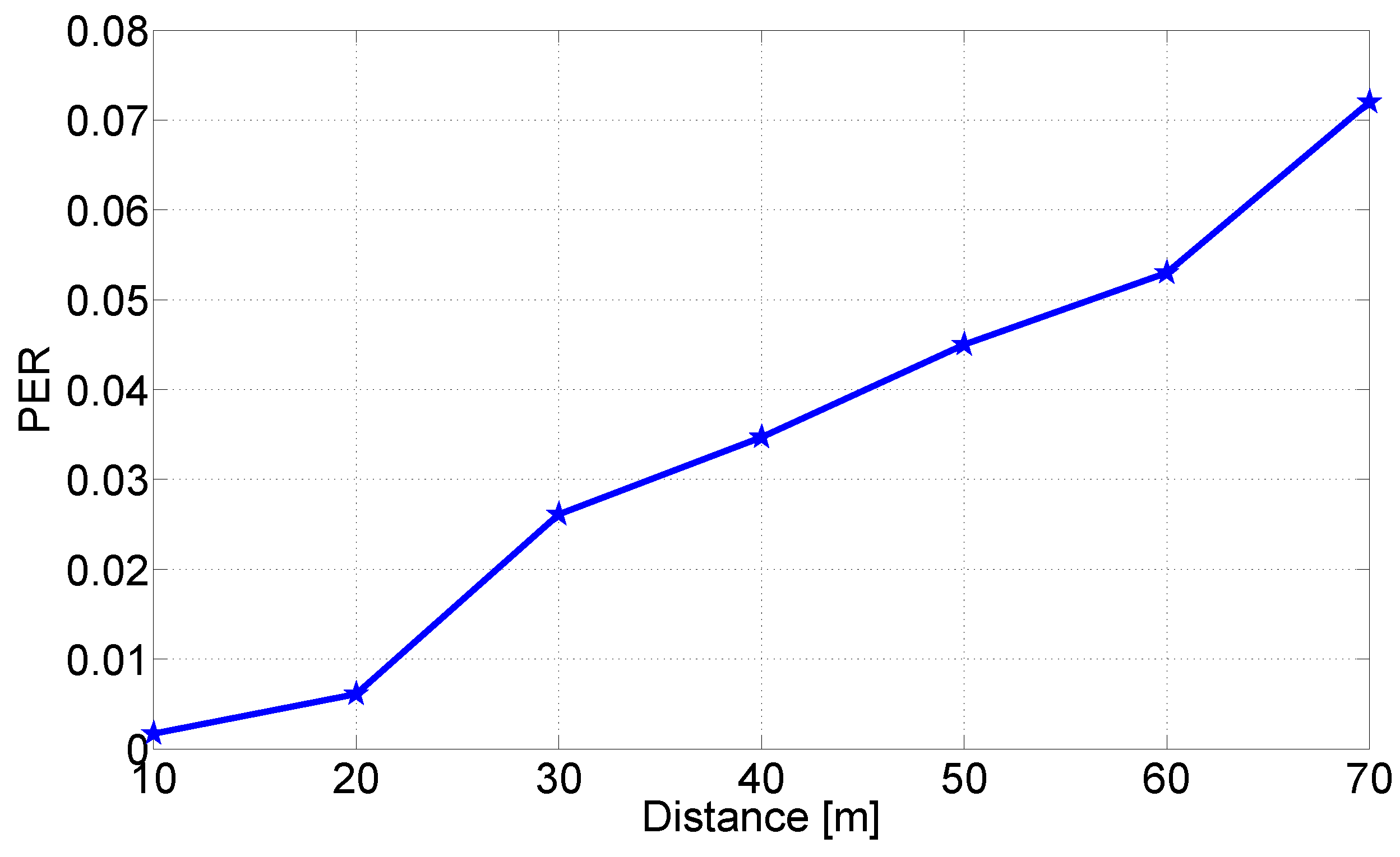
As expected, according to the experimental results shown in Figure 8, the PER is an increasing function of the inter-node distance. Furthermore, the shape of the experimental curve appears to be approximately linear. According to the results in Figure 8, it emerges that for d = 60 m, the PER is equal to 0 . 054 . We consider this value of d as the experimental transmission range, z, inside the IF PAF defined in Equation (1)—this experimental value is lower than the open space transmission range claimed by the IEEE 802.11 standard [31]. Note that, with respect to the tests performed in Subsection 5.2.1, the PER in Figure 8 is much lower, because in this case, the test are carried out in more favorable conditions (almost free space).
Figure 8. Experimental PER as a function of the inter-node distance, by considering P tx = 32 mW and R = 11 Mb/s.
Futureinternet 05 00398 g008

5.3. Tests in Ideal Static Scenarios

As aforementioned, in the second phase of our experimental campaign, we perform a number of field tests in ideal scenarios, where the nodes are static and positioned in an environment not affected by phenomena like shadowing and fading. In the considered experimental conditions, the wireless medium access problem cannot be extensively analyzed, and the IF protocol does not perform at its best. The number of retransmission choices is, in a probabilistic sense, very small. Although a larger number of nodes should be considered (e.g., at least 15–20 devices) in order to have higher node spatial density, the obtained results shed light on the performance of the proposed information dissemination system.

5.3.1. Experimental Setup and Results

We evaluate the performance of the X-NETAD application in two different static scenarios, which are illustrated in Figure 9. For each test, the transmit power, P t , of each device was set to its maximum value, equal to 32 mW, and the data rate, R, was fixed at 11 Mb/s—the rate that guarantees the minimum experimental PER, as shown in Subsection 5.2.1. According to the results presented in Subsection 5.2.2, we use the value, 60 m, as the device’s transmit range, z, to be used in the IF protocol. The linear node spatial density, ρ s , is related to the considered scenario, since it depends on the (physical) spatial distribution of the nodes. The shaping coefficient, c, is set to 5 to balance the small number of nodes present in the system and, thus, to increase the rebroadcasting probability. In each test, the application disseminates the same archive of roughly 100 KB, divided in 128 chunks. During tests, we considered, as an expiration date for each content, T q = 60 s: the choice of this value allows significant information propagation. Finally, the waiting time before sending a REQUEST message is set to 5 s.
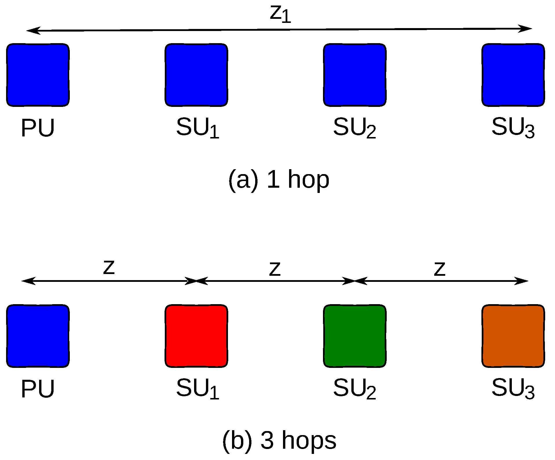
Figure 9. Static X-NETAD application testbed: (a) Scenario 1, all Secondary Users (SUs) are located in the transmission range of the PU; (b) Scenario 2, each SU is at the edge of the transmission range of previous nodes.
Futureinternet 05 00398 g009

5.3.2. Scenario 1

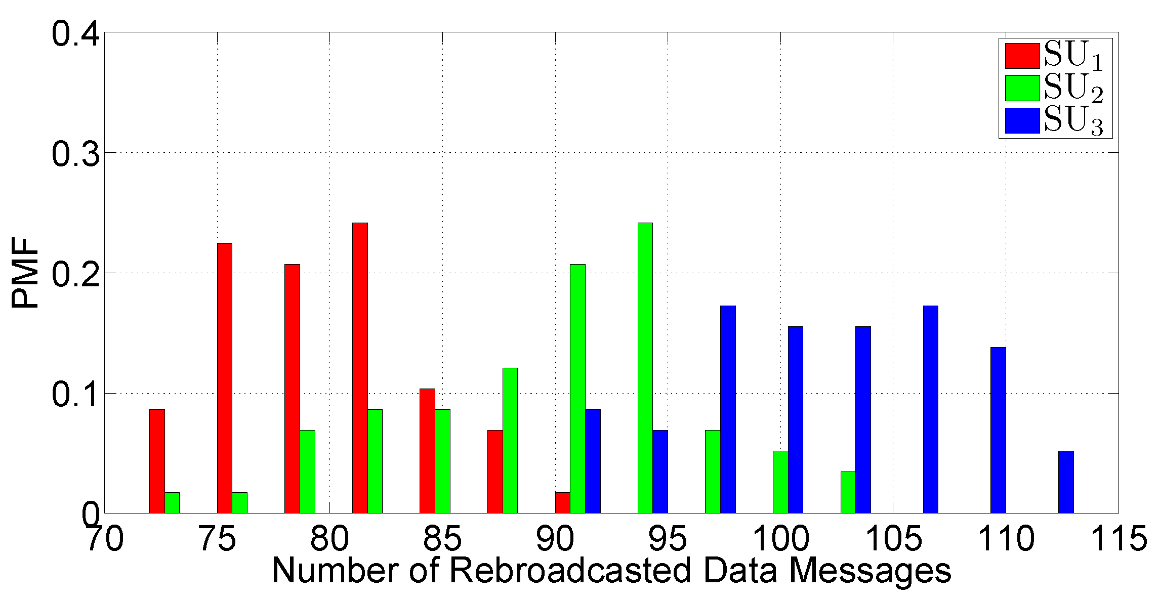
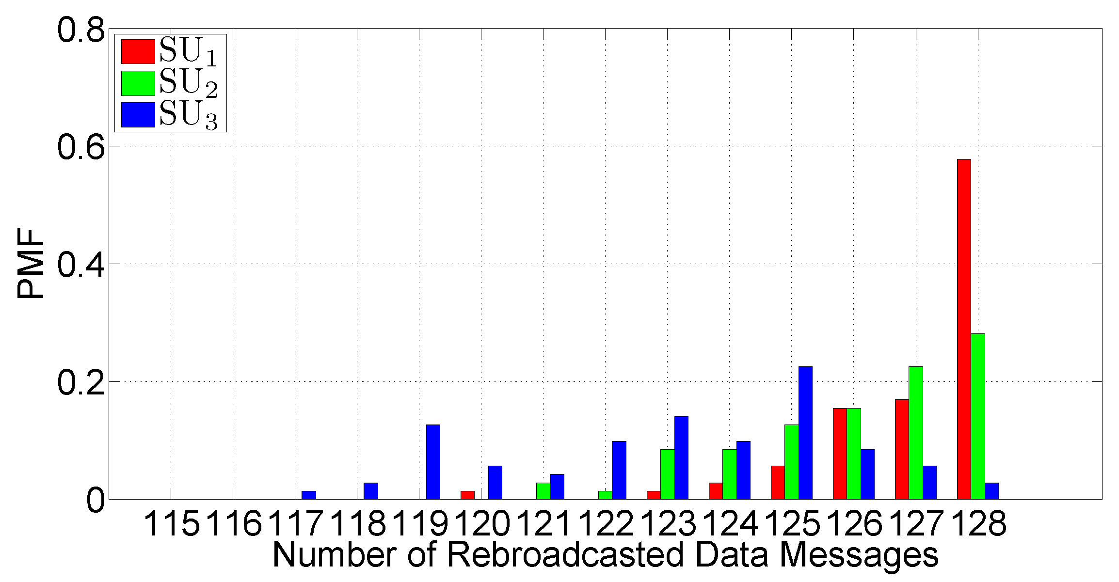
This scenario presents the most intense level of channel access contention, since all the SUs are within the transmission range of the PU, as shown in Figure 9a. The linear spatial density, ρ s , is equal to 0 . 05 veh/m, and the total number of SUs is given by ρ s z = 3 veh. In Figure 10, the experimental PMF of the number of rebroadcast DATA messages at each SU is shown. As one can observe, the rebroadcasting probability of SUs is strictly correlated to their distances from the PU [see Equation (1)]. Fluctuations around average values of the rebroadcasting probability depend on errors in GPS localization.
Figure 10. Probability Mass Function (PMF) of rebroadcast DATA messages in Scenario 1.
Futureinternet 05 00398 g010
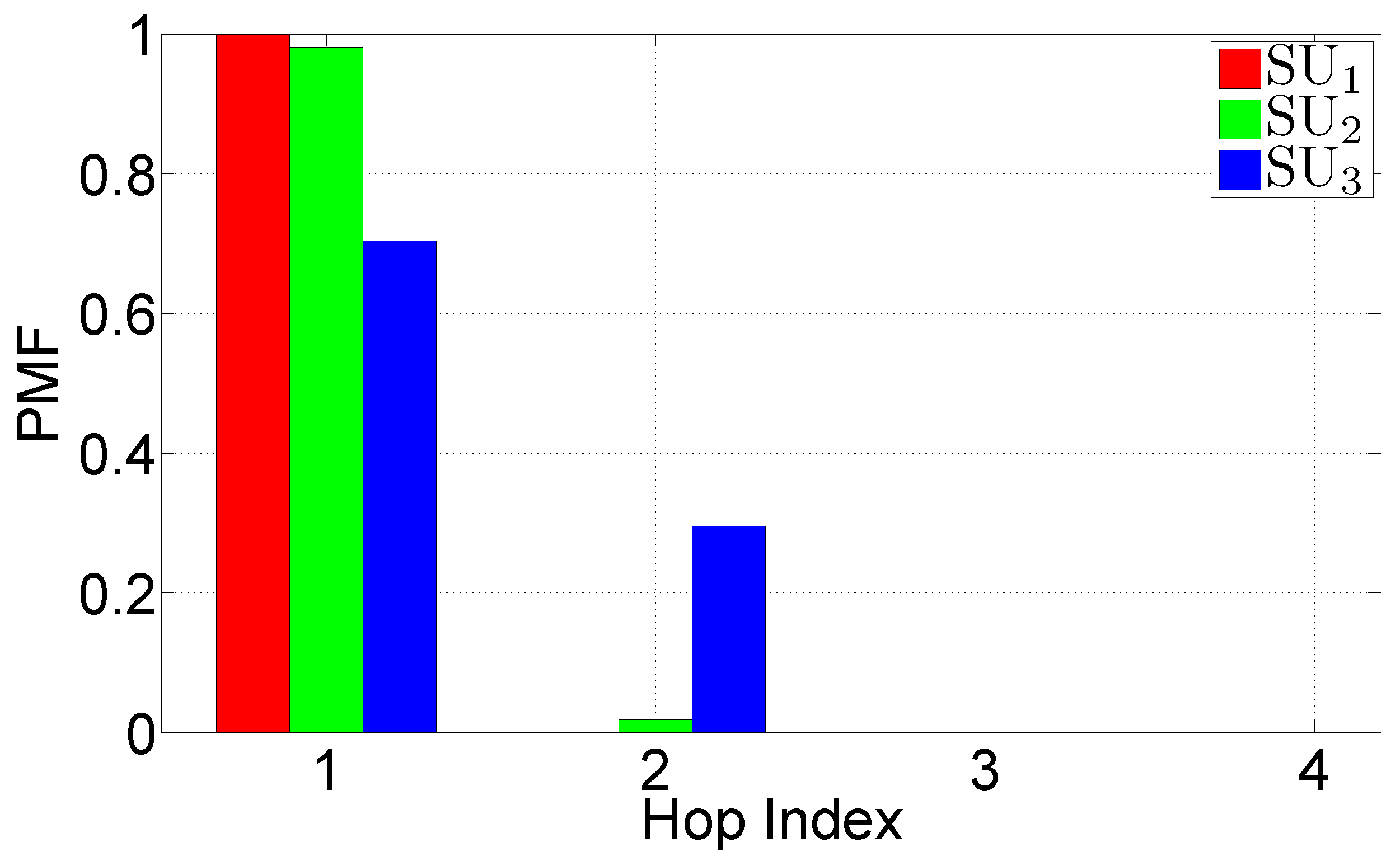
In Figure 11, the PMF of the hop reception index of DATA messages at each SU is shown. In principle, all SUs should receive all messages directly from the PU, because they are within the transmission range of the latter. Nevertheless, even though some messages might be lost because of channel impairments, they can still be received, as information propagation is guaranteed by the rebroadcasting nature of the IF protocol. For this reason, we found that some DATA messages are received with a hop index equal to 2. This proves that probabilistic rebroadcasting adds redundancy, which, in turn, increases the system reliability.
Figure 11. Hop index PMF for received DATA messages in Scenario 1.
Futureinternet 05 00398 g011
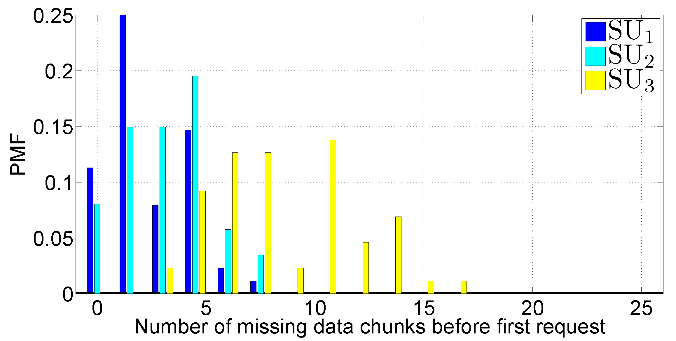
Despite this, there is a chance that a certain message may be lost. In Figure 12, the PMF of the number of missing chunks at a given node, before the first REQUEST round, is shown. It can be pointed out that in this scenario, both SU 1 and SU 2 experience a small number of lost DATA messages (smaller than the 10 % of DATA messages sent), while SU 3 experiences a higher loss ratio, due to the fact that its distance from PU is longer. Moreover, from Figure 12, one can see that SU 3 always misses at least one chunk, while SU 1 and SU 2 sometimes (with a probability higher than 10 % ) do not need to send any feedback message.
Figure 12. PMF of missing DATA chunks, before the first REQUEST round in Scenario 1.
Futureinternet 05 00398 g012
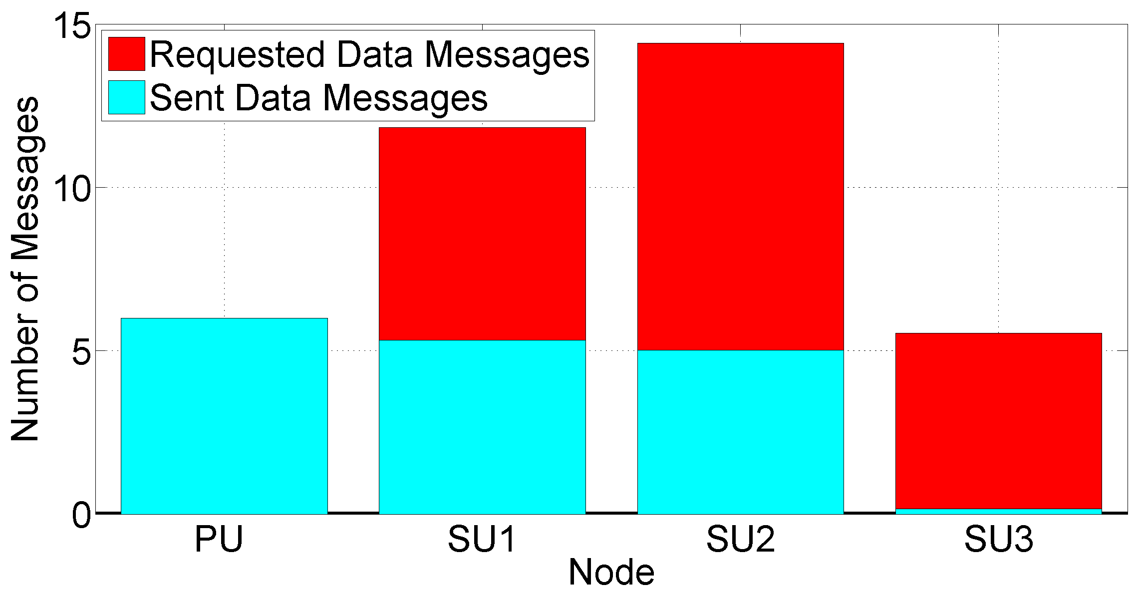
At this point, it is worth investigating which nodes receive and satisfy the largest number of REQUEST messages. For this purpose, in Figure 13, we show the total number of missing DATA chunks requests, received by a given node, and the total number of DATA messages replied by the node as a result of previous requests. According to these results, SU 1 and SU 2 receive the largest number of packet requests. However, the larger number of replies is given by PU 1 , since it does not adopt a probabilistic broadcasting protocol (in fact, it satisfies the 100 % of requests). SUs have a much lower satisfaction ratio, which reduces as the distance from the PU 1 rises: this is due to Equation (2) and because a node cannot satisfy a REQUEST for a packet that has not yet been received.
Figure 13. Average number of DATA chunks requested and average number of DATA messages sent following a REQUEST, in Scenario 1.
Futureinternet 05 00398 g013
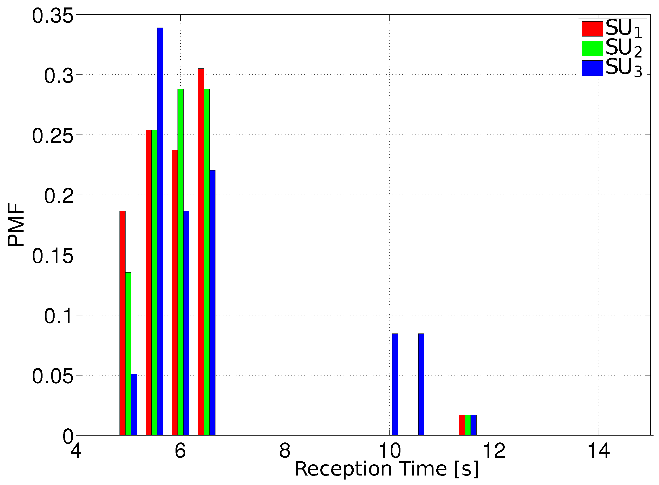
Finally, in Figure 14, the PMF of the traffic updates reception time is shown. It can be observed that, on average, all nodes have a completion time (i.e., all the DATA messages of a given archive are received) lying in the interval, [5–7] s: this means that only one REQUEST message is sent back (we recall that W req = 5 s). The exception is represented by SU 3 , which completes the reception of all DATA messages in more than 10 s with a probability around 0 . 18 .
Figure 14. PMF of the archive reception time in Scenario 1.
Futureinternet 05 00398 g014
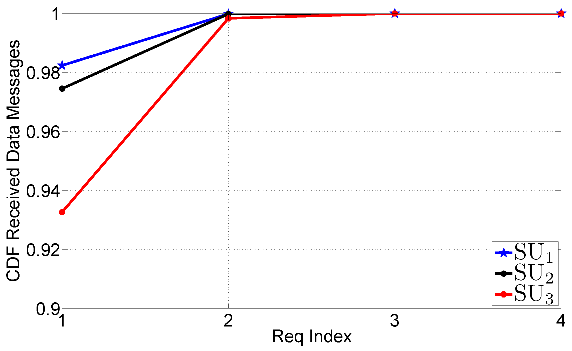
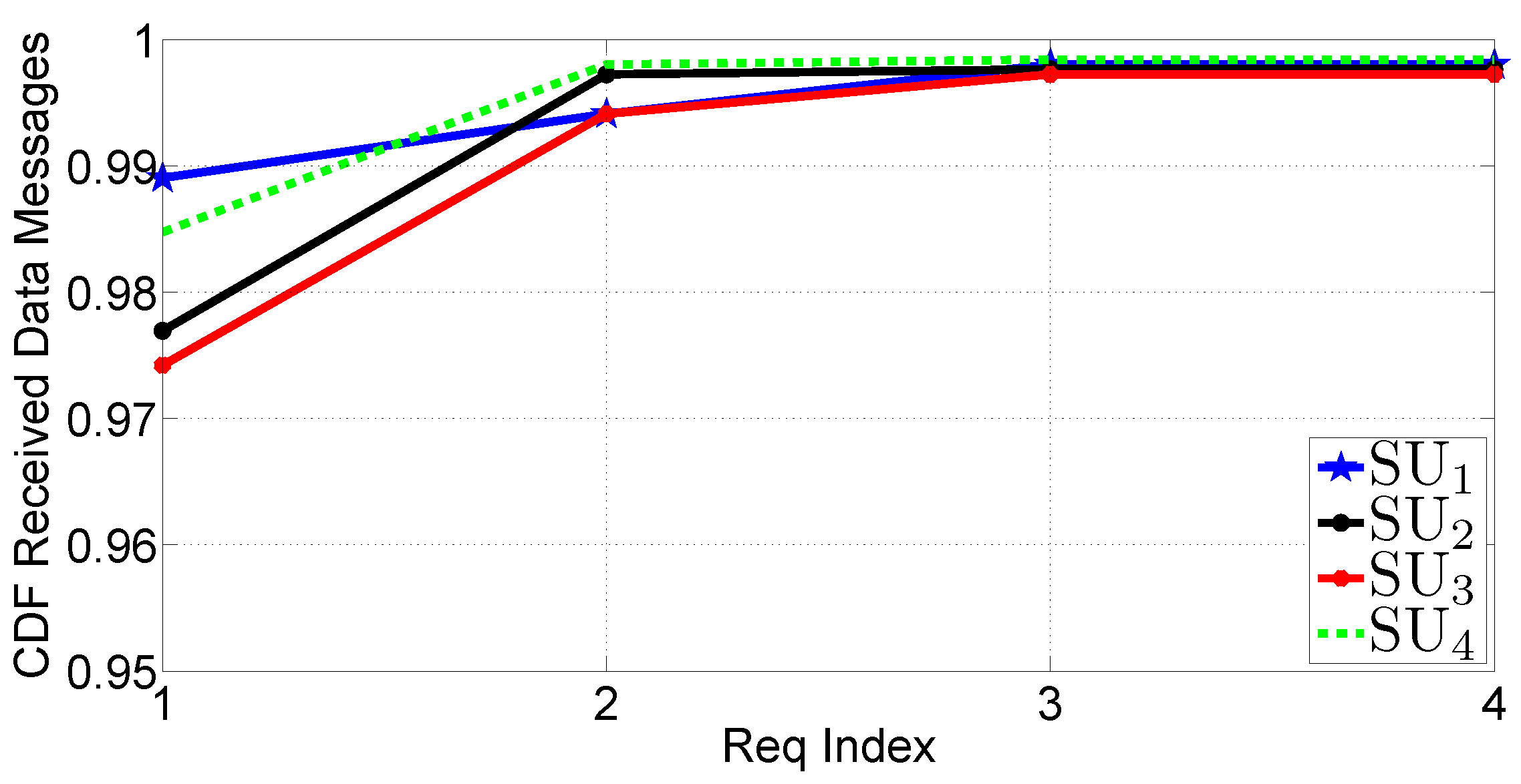
In order to have a better comprehension of this phenomenon, in Figure 15, the CDF of received DATA messages is shown as a function of the number of REQUEST messages. One can see that before the first REQUEST, SU 1 typically has a completion rate equal to 0 . 98 , while SU 2 and SU 3 achieve slightly smaller values (equal to 0 . 97 and 0 . 93 , respectively). Hence, in this scenario, all the SUs can complete the reception before the second REQUEST with a high probability.
Figure 15. Cumulative Distribution Function (CDF) of received DATA messages before REQUEST messages in Scenario 1.
Futureinternet 05 00398 g015

5.3.3. Scenario 2

In this scenario, shown in Figure 9b, it is assumed that each node is located at the edge of the transmission range of the preceding node. For this reason, multi-hop communications are needed to disseminate traffic updates throughout the network, and this degrades the performance. In particular, the PMF of the retransmitted DATA messages is presented in Figure 16. We note that, with respect to Scenario 1, the rebroadcasting probability is (obviously) higher for all SUs ( d = z ). The number of retransmissions is upper bounded by 128, which represents the number of chunks in which the archive is fragmented.
Figure 16. PMF of the number of rebroadcast DATA messages in Scenario 2.
Futureinternet 05 00398 g016
In Figure 17, the PMF of the received DATA messages is shown. It can be observed that, for each SU, there exists, also, the possibility to receive messages from other SUs, due to the feedback mechanism detailed in Section 4.2.2. For instance, some DATA messages received by SU 3 are one-hop messages, because they come from SU 2 and are sent after the reception of a REQUEST message. Nevertheless, we note that for all SUs, there is a dominant hop value centered at their distance (in terms of hops number) with respect to the PU.
Figure 17. PMF of the hop index for received DATA messages in Scenario 2.
Futureinternet 05 00398 g017
As can be seen from Figure 18, the number of missing chunks before the generation of the first REQUEST message is larger than in the previous case, thus significantly penalizing Scenario 2 with respect to Scenario 1. In particular, it can be noted that: (i) each SU needs to use at least one REQUEST message; and (ii) the number of missing chunks is, for each run, larger than 10. It can also be noted that SU 3 is particularly penalized, because the link losses generate cumulative effects.
Figure 18. PMF of missing DATA chunks, before first REQUEST round in Scenario 2.
Futureinternet 05 00398 g018
In Figure 19, the PMF of the archive completion time is shown. As expected, the reception time is longer than in Scenario 1. The difficulty of receiving all the chunks is evidenced by the larger number of REQUEST rounds for missing chunks that contribute to increase the completion time.
Figure 19. PMF of the archive reception time in Scenario 2.
Futureinternet 05 00398 g019
Finally, in Figure 20, the PMF of the completion time before the first REQUEST message is shown, which is around 0 . 7 , 0 . 65 and 0 . 55 , respectively, for SU 1 , SU 2 and SU 3 . The use of a single feedback REQUEST message raises the completion rate to a value of about 0.9 for each node. Hence, on average, at least one or even more REQUEST messages are required to complete the reception of the archive.
Figure 20. CDF of received DATA messages before REQUEST messages in Scenario 2.
Futureinternet 05 00398 g020

5.4. Tests in a Mobile Scenario

In the third phase of our field tests, we consider a more realistic scenario, denoted as Scenario 3, in the following, where the smartphones are positioned within vehicles moving along a predetermined path. The experimental setup is described in Subsection 5.4.1, while the obtained results are discussed in Subsection 5.4.2.

5.4.1. Scenario Description

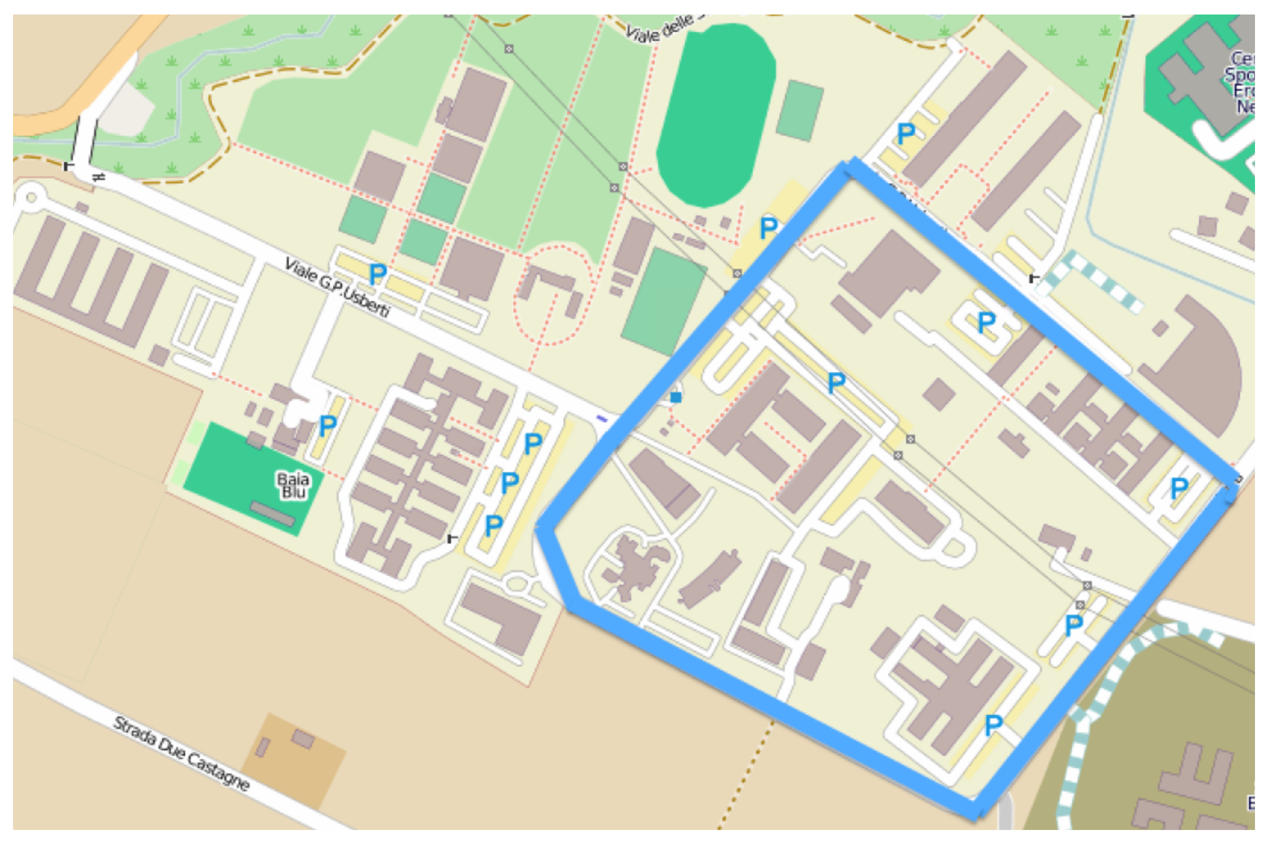
We consider a single PU and four smartphones acting as SUs. The PU is placed in a given car, while the remaining smartphones ( SU 1 , SU 2 , SU 3 and SU 4 ) are positioned in distinct vehicles. The vehicles move assuming a platoon configuration led by the PU. For the whole duration of the experiment, the vehicle with SU 1 remains behind the car containing the PU, while the other vehicles periodically exchange their positions. During the test, the smartphones are held by the driver or positioned within the cockpit (e.g., over the seats or over the dashboard). The five vehicles involved in the tests complete 20 laps of the circuit shown in Figure 21, designed within the campus of the University of Parma. The circuit path length is 1 . 72 km, and the vehicles completed the test with an average speed of roughly 40 km/h ( 11 . 1 m/s) and maintaining an inter-vehicle distance within the interval, [10–30] m. (The average speeds and the inter-node distances are obtained by means of GPS.) Since the test has been conducted on a public road, sporadically, other cars have disturbed the platoon configuration. At every lap, the PU sends two distinct archives: one at the beginning of the lap and the second at the middle of the lap. Therefore, the results shown here have been obtained averaging over 40 transmission acts conducted in 20 laps of the circuit.
Figure 21. Circuit followed by the vehicles during the tests. Image taken from Open Street Map.
Futureinternet 05 00398 g021

5.4.2. Experimental Results

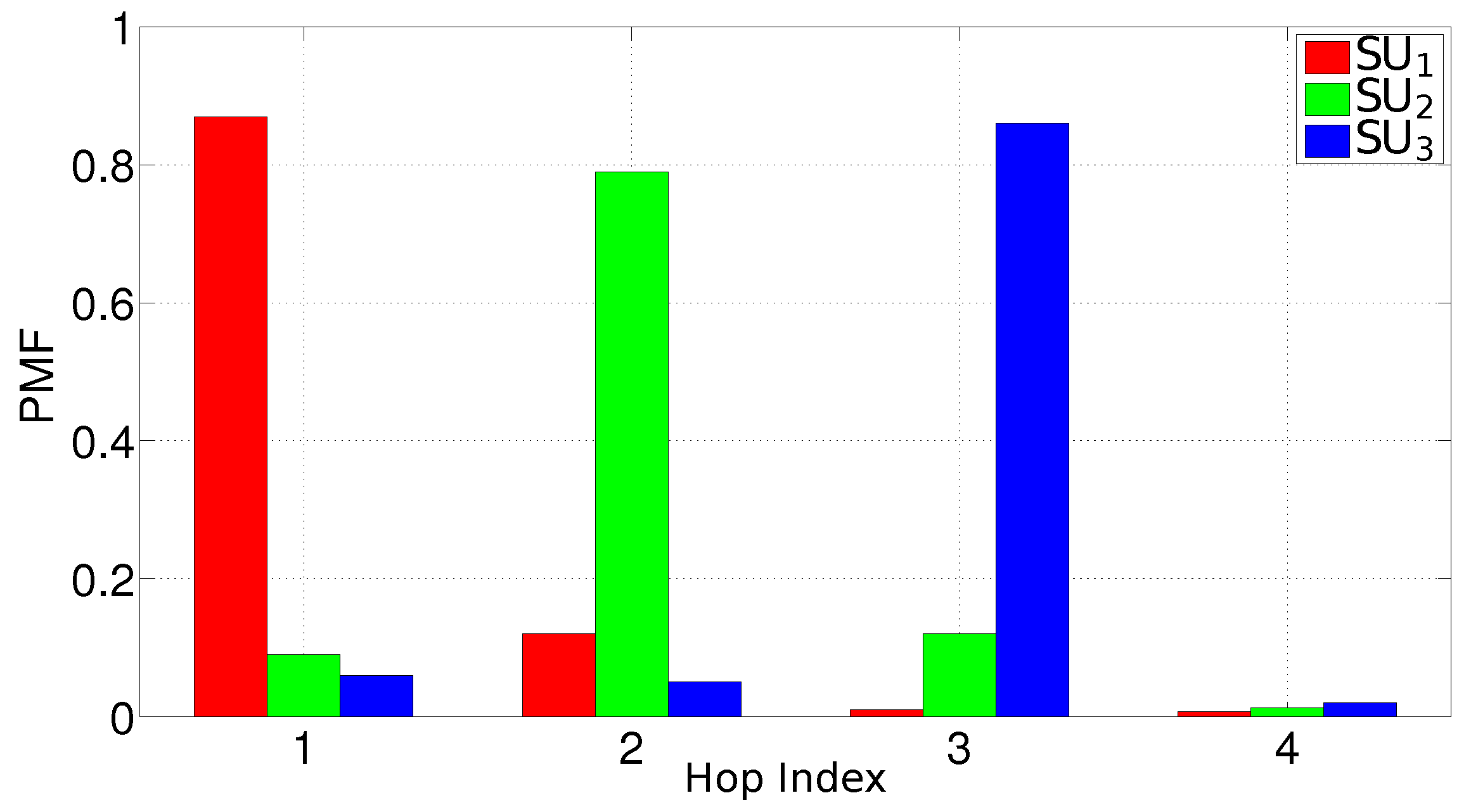
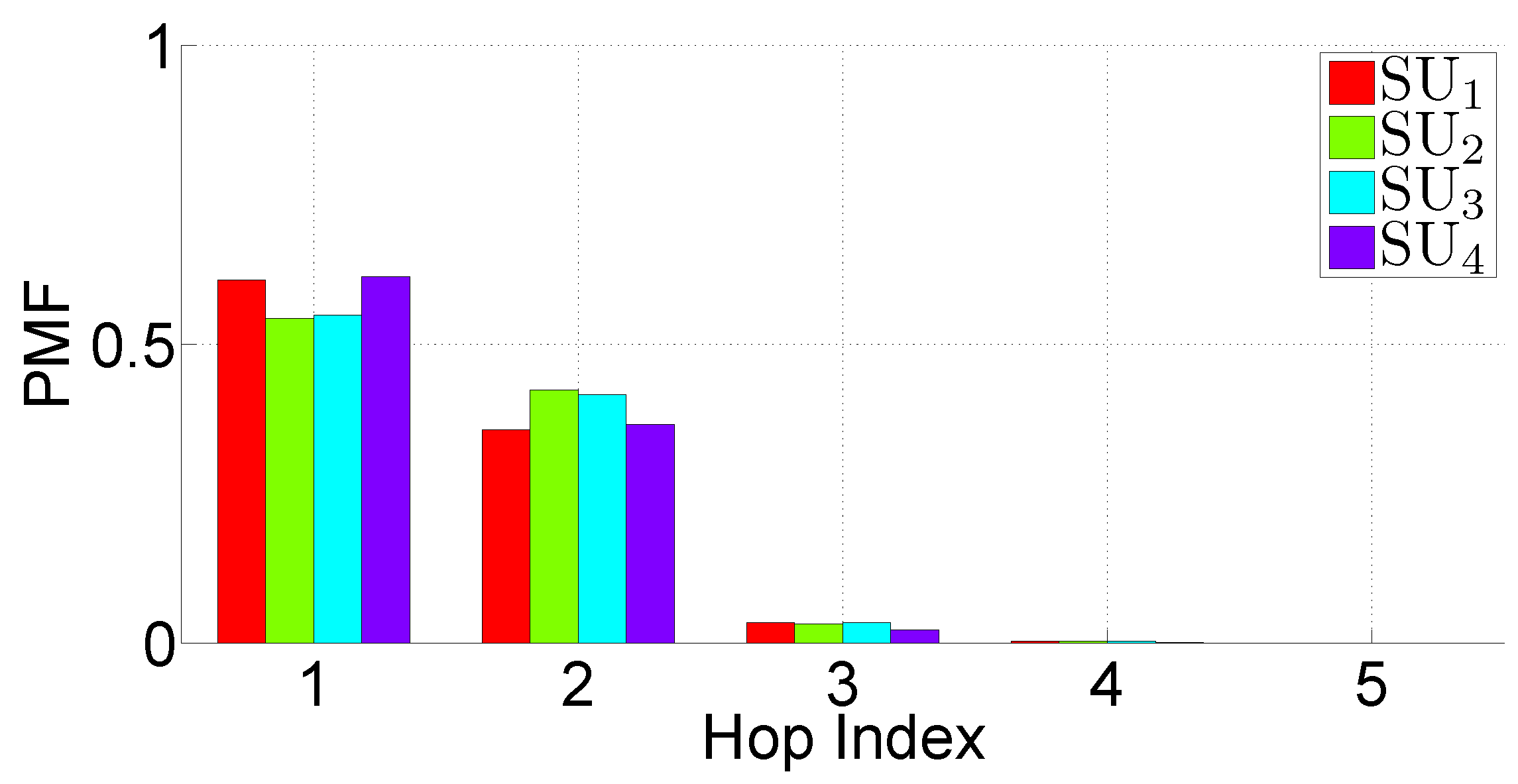
In Figure 22, the PMF of the hop index, at which messages are received, is shown. From the results in the figure, it can be observed that the “average” network topology emerges from the test. In particular, it can be observed that for all the SUs, 95% of the fragments are received within the first two communication hops. In other words, in the majority of the cases, the SUs have been in direct visibility (or at least two hops away) from the PU. Therefore, we expect a performance comparable to that observed in Scenario 1.
Figure 22. PMF of the hop index at which DATA messages are received in Scenario 3.
Futureinternet 05 00398 g022
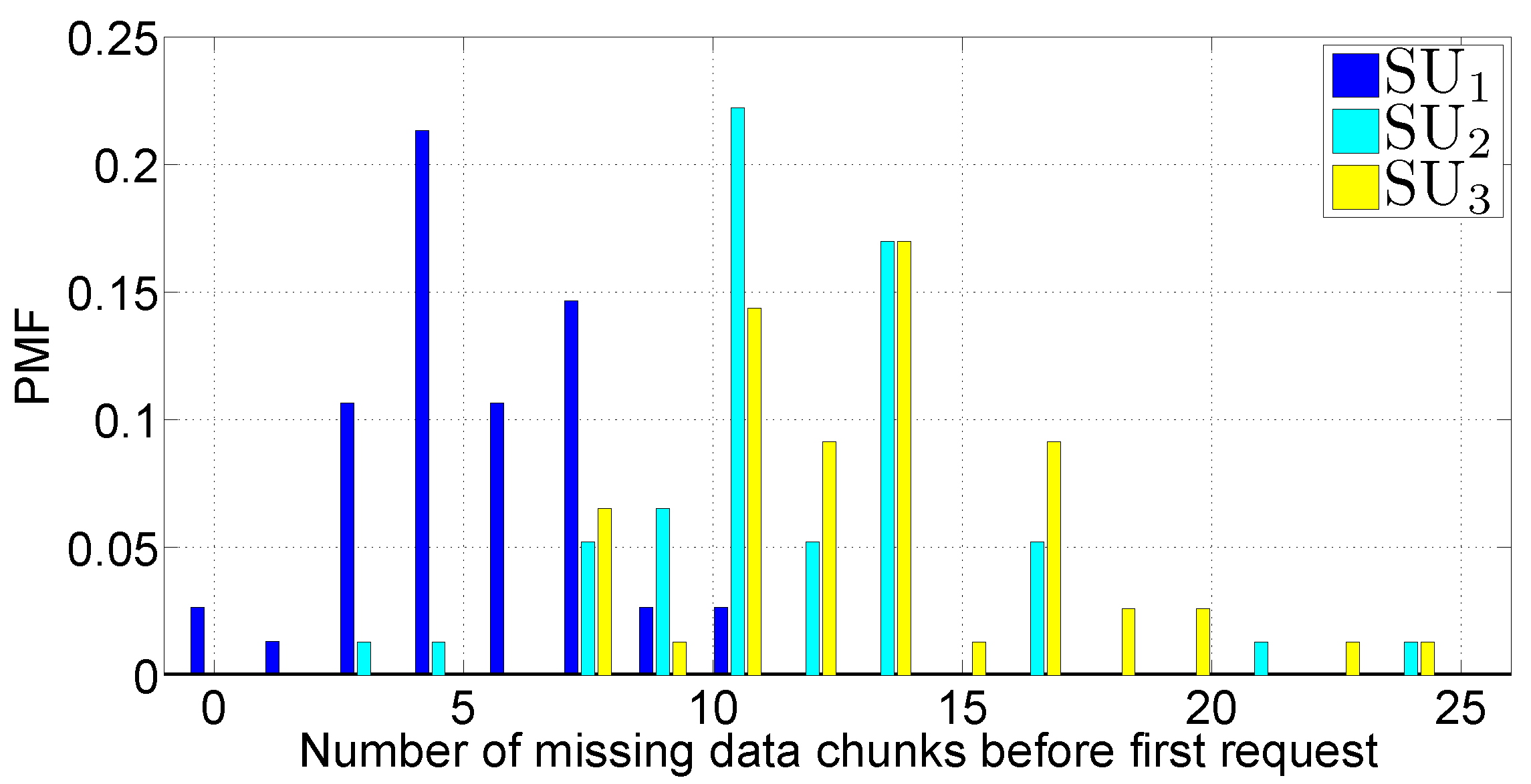
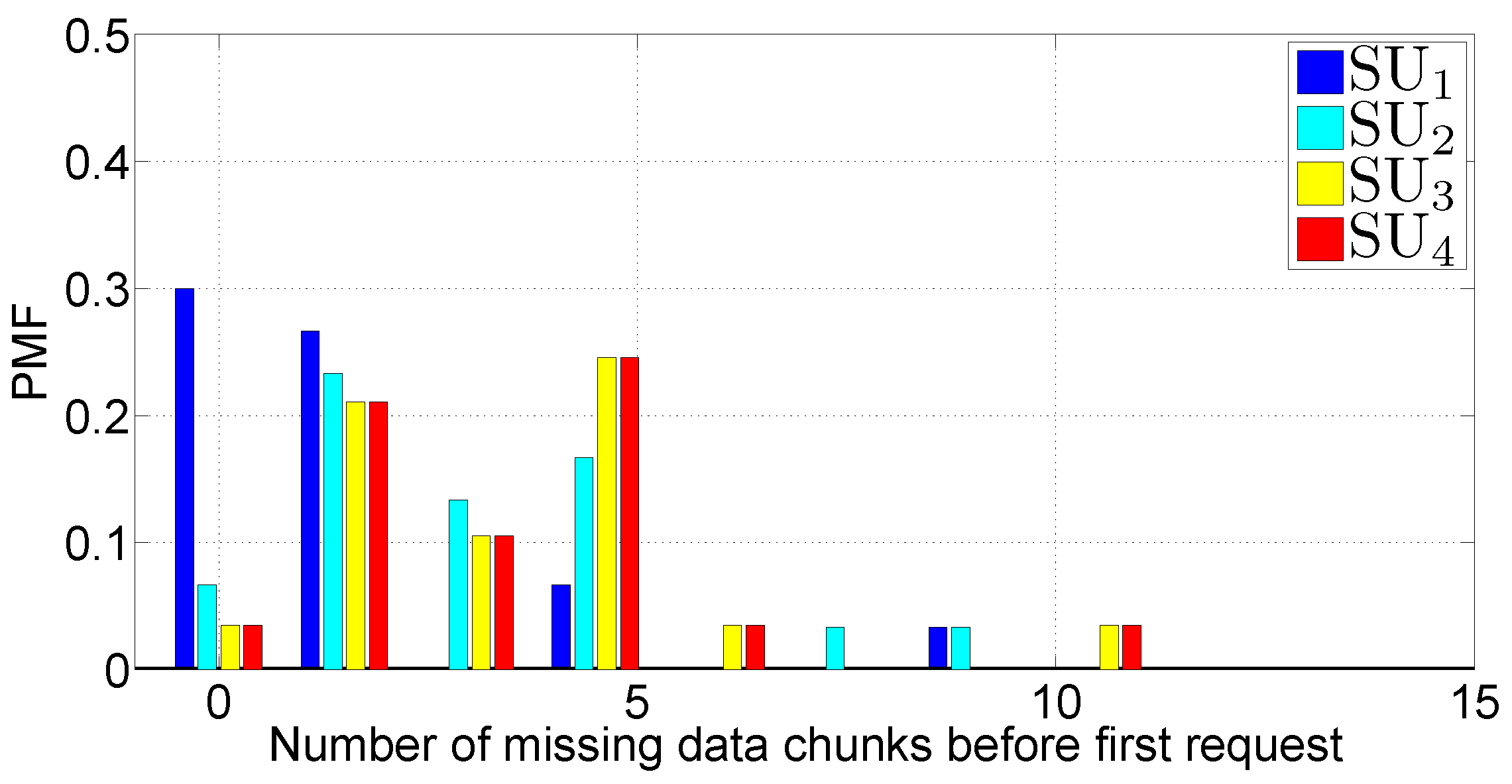
From the point of view of the number of missing packets after the first transmission of the PU, from Figure 23, it can be observed that the performance is comparable with that obtained by SU 2 and SU 3 in Scenario 1. A remarkable exception is represented by the node, SU 1 , which exhibits excellent performance in Scenario 3.
Figure 23. PMF of the number of missing DATA fragments before the transmission of the first REQUEST message in Scenario 3.
Futureinternet 05 00398 g023
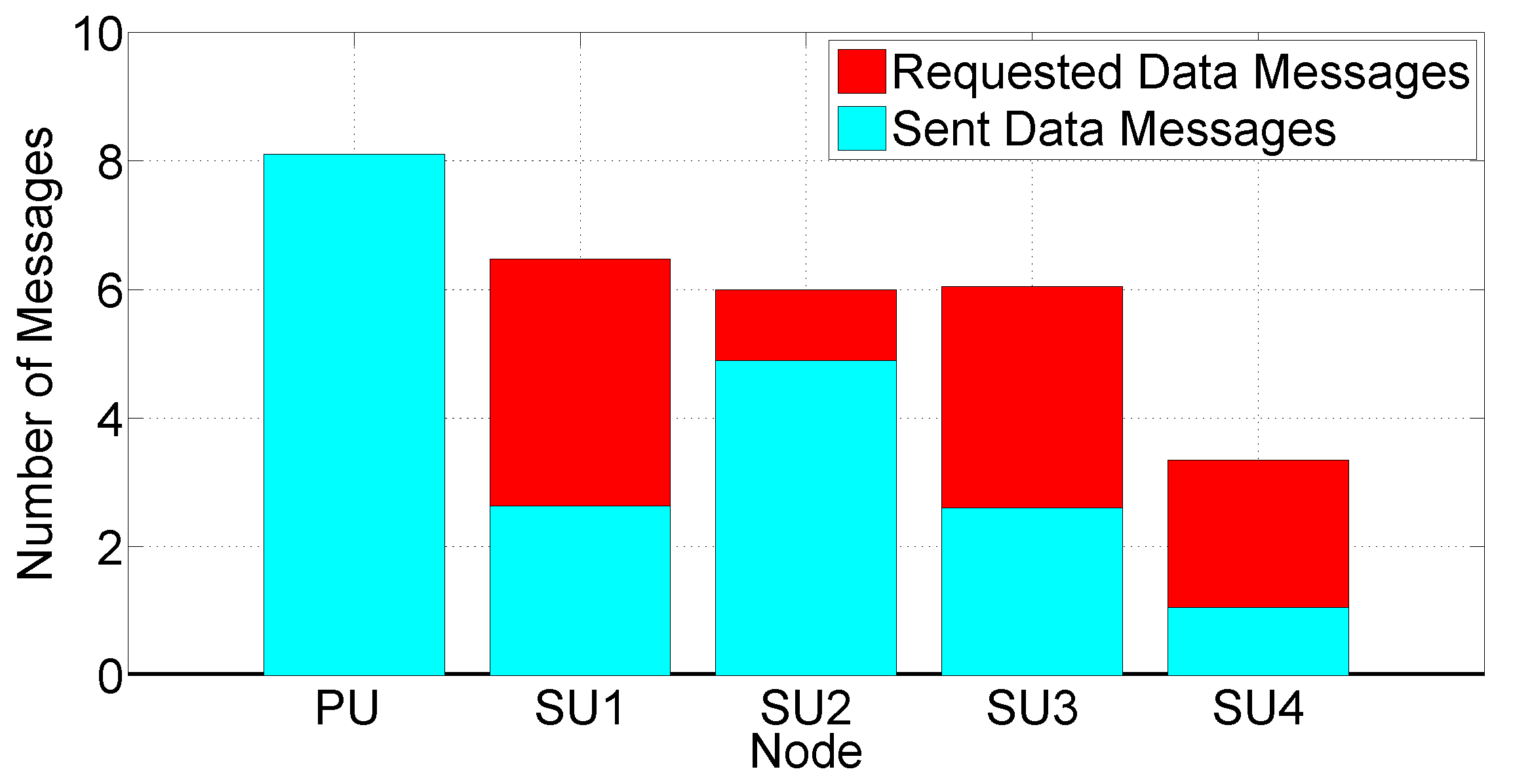
Similarly, also from Figure 24, it can be observed that the behavior, in terms of requested messages and satisfied messages, is comparable to that observed in Scenario 1. However, there is a significant difference with respect to Scenario 1. In the latter, the larger fraction of requests is satisfied by the PU, while in Scenario 3, the SUs play a more important role.
Figure 24. Number of requested DATA messages and number of replica DATA messages sent upon the reception of a request, in Scenario 3.
Futureinternet 05 00398 g024
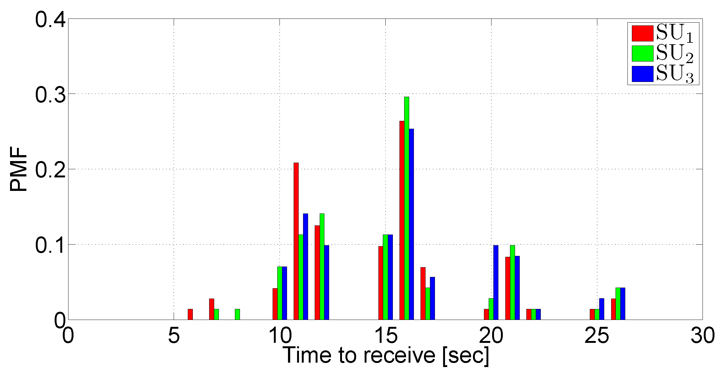
By observing Figure 25, it is possible to get some interesting insights, concerning the main differences between Scenario 1 and Scenario 3. First of all, it can be observed that the archive is received only after a first round of REQUEST messages and subsequent retransmissions. Moreover, a network bimodal behavior can be observed:
  • the archive is received in a very short time (after 1 or 2 REQUEST message rounds)—this happens when the network conditions are good and stationary;
  • the archive is received after a large number of rounds (5 or 6)—this happens when the network homogeneity disappears because of phenomena that break the network topology, such as the presence of other vehicles fragmenting the platoon or an excessive inter-vehicle distance.
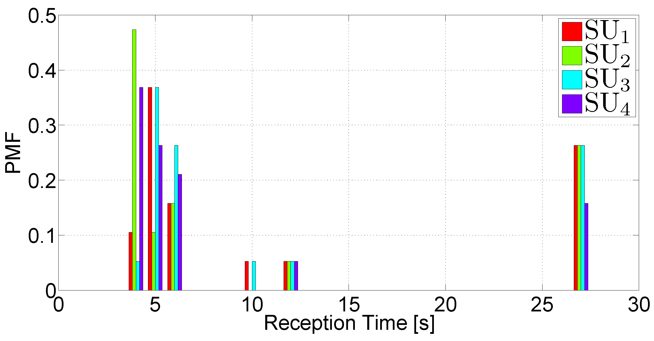
Figure 25. PMF of the archive reception time in Scenario 3.
Futureinternet 05 00398 g025
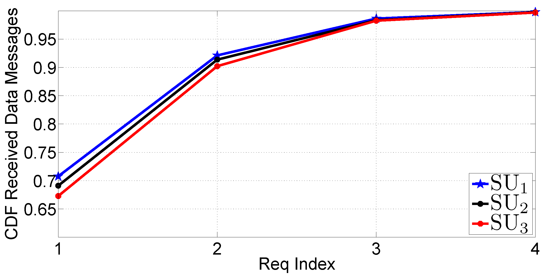
Finally, in Figure 26, the CDF of the received DATA messages, before a REQUEST, is shown. The obtained results justify the conclusions reached in the previous paragraph (relative to the results in Figure 25). In fact, it can be observed that a small number of rounds is often sufficient to collect the majority of fragments. However, a significantly longer time is required for completing the reception of the entire archive.
Figure 26. CDF of the received DATA messages before a REQUEST in Scenario 3.
Futureinternet 05 00398 g026
To summarize, the obtained results show that the performance on a realistic scenario, even if simplified by keeping an almost constant vehicle speed and a limited inter-vehicle distance, has been shown to be similar to that obtained in Scenario 1 and even better than that obtained in Scenario 2.

5.5. Discussion

The results obtained from the experimental campaign have confirmed the good performance exhibited by the data dissemination protocol adopted in X-NETAD. In fact, it has been shown that a small number of rounds of requests (at most five) is sufficient to disseminate the whole information archive to all network nodes. This happens also in the case of unfavorable network conditions (as in the case of Scenario 2), where SUs are sparse and distant from the PU (up to three hops away). Remarkably, these results have been obtained limiting the overall number of transmissions in the network.
The core retransmission mechanism of X-NETAD is the IF broadcast protocol, which is designed to reduce the channel congestion and, thus, scales well with the number of nodes, as shown in [26]. The presented results have been obtained in scenarios with a small number of nodes, where the impairments of the wireless channel are the principal cause of the packet losses, while the losses due to channel congestion are negligible. However, we expect that the overall performance of the X-NETAD protocol should scale well with the number of nodes, owing to the equivalent property of the IF protocol.
Finally, we comment on a comparison between the performance of the X-NETAD protocol with that of other dissemination protocols. Even if we do not have conducted experimental campaigns using alternative protocols, it is possible to get some insights from some of our previous works [27]. In particular, according to the observations in Subsection 3.1, the IF protocol exhibits better performance than the flooding protocol, especially under heavily loaded networks. Unfortunately, as our testbed is composed of a small number of smartphones, we were not able to evaluate scenarios with high spatial densities. Therefore, in our specific experimental scenario, it is reasonable to expect that a flooding-based dissemination strategy will exhibit a performance similar to that of IF.

6. Conclusions

In this paper, we have presented a novel traffic information dissemination system, denoted as X-NETAD and developed in a bilateral Italy-Israel research project [11]. Under the assumption of the presence of (at least) one smartphone in each car, the key idea of the X-NETAD approach is that of electing “primary” nodes that receive traffic alerts from the cellular (3G and, in perspective, 4G) network and broadcast them very rapidly, through WiFi communications, to all vehicles (denoted as “secondary” nodes) in their neighborhoods. The X-NETAD application has been implemented and validated on a realistic testbed based on Android-powered smartphones, shedding light on the limits and benefits of a smartphone-based vehicular communication system. Interestingly, the paradigm behind the X-NETAD approach maintain its validity also in more generic scenarios, where smartphones can be substituted by infotainment in-car devices equipped with multiple network interfaces. For these reasons, the obtained results are very encouraging, and the X-NETAD approach paves the way to future Internet architectures involving vehicles.

Acknowledgments

The work of S. Busanelli, N. Iotti and G. Ferrari was carried out under the one-year project “Cross-Network Effective Traffic Alerts Dissemination” (X-NETAD, Eureka Label E! 6252 [11], 2011–2012), sponsored by the Ministry of Foreign Affairs (Italy) and The Israeli Industry Center for R&D (Israel) under the “Israel-Italy Joint Innovation Program for Industrial, Scientific and Technological Cooperation in R&D.” F. Rebecchi was at the University of Parma (2011) while collaborating with S. Busanelli and G. Ferrari within the X-NETAD project.

Conflict of Interest

The authors declare no conflict of interest.

References

  1. Hartenstein, H.; Laberteaux, K. VANET Vehicular Applications and Inter-Networking Technologies; John Wiley & Sons: Chichester, UK, 2010. [Google Scholar]
  2. Insitute of Electrical and Electronics Engineers. IEEE Standard for Information technology—Telecommunications and Information Exchange between Systems—Local and Metropolitan Area Networks–Specific Requirements Part 11: Wireless LAN Medium Access Control (MAC) and Physical Layer (PHY) Specifications Amendment 6: Wireless Access in Vehicular Environments; IEEE Standard 802.11p-2010 (Amendment to IEEE Std 802.11-2007); IEEE: Washington, DC, USA, 2010; pp. 1–51. [Google Scholar]
  3. European Profile Standard for the Physical and Medium Access Control Layer of Intelligent Transport Systems Operating in the 5 GHz Frequency Band; ETSI ES 202 663 V1.1.0; ETSI: Sophia-Antipolis, France, 2010; pp. 1–27.
  4. Araniti, G.; Campolo, C.; Condoluci, M.; Iera, A.; Molinaro, A. LTE for vehicular networking: A survey. IEEE Commun. Mag. 2013, 51, 148–157. [Google Scholar] [CrossRef]
  5. Nye, S. Connected Vehicle Survey. Technical Report for Informa Telecoms&Media: London, UK, 2012. Available online: http://connectedcarsworld.com/wp-content/uploads/connectedcw13/2013/02/Informa Connected Vehicle Survey interim results.pdf (accessed on 22 July 2013).
  6. Vinel, A. 3GPP LTE versus IEEE 802.11p/WAVE: Which technology is able to support cooperative vehicular safety applications? IEEE Wirel. Commun. Lett. 2012, 1, 125–128. [Google Scholar] [CrossRef]
  7. Intelligent Transport Systems (ITS). Framework for Public Mobile Networks in Cooperative. ITS (C-ITS); ETSI: Sophia-Antipolis, France, 2012. [Google Scholar]
  8. Vandenberghe, W.; Moerman, I.; Demeester, P. On the Feasibility of Utilizing Smartphones for Vehicular Ad Hoc Networking. In Proceedings of the ITS Telecommunications (ITST), 2011 11th International Conference on IEEE, Saint-Petersburg, Russia, 28–30 August 2011; pp. 246–251.
  9. Baiocchi, A.; Cuomo, F. Infotainment services based on push-mode dissemination in an integrated VANET and 3G architecture. J. Commun. Netw. 2013, 15, 179–190. [Google Scholar] [CrossRef]
  10. Ferrari, G.; Busanelli, S.; Iotti, N.; Kaplan, Y. Cross-network Information Dissemination in VANETs. In Proceedings of the 11th International Conference on Telecommunications for Intelligent Transport Systems (ITST-2011), IEEE, Saint-Petersburg, Russia, 28–30 August 2011; pp. 351–356.
  11. Eureka Project 6252 X-NETAD. Available online: http://www.eurekanetwork.org/project/-/id/6252 (accessed on 22 July 2013).
  12. Avni, O. Performance and Limitations of Cellular-based Traffic Monitoring Technologies: Based on Case Study of Benchmarking Cellint’s TrafficSense with Road Sensors. In Proceedings of the Institute of Transportation Engineers (ITE) Technical Conference and Exhibit, San Diego, CA, USA, 25–28 March 2007.
  13. Calabrese, F.; Colonna, M.; Lovisolo, P.; Parata, D.; Ratti, C. Real-time urban monitoring using cell phones: A case study in Rome. Intell. Transp. Syst. IEEE Trans. 2011, 12, 141–151. [Google Scholar] [CrossRef]
  14. Rybicki, J.; Scheuermann, B.; Kiess, W.; Lochert, C.; Fallahi, P.; Mauve, M. Challenge: Peers on Wheels-a Road to New Traffic Information Systems. In Proceedings of the 13th Annual ACM International Conference on Mobile Computing and Networking, Montréal, QC, Canada, 9–14 September 2007; pp. 215–221.
  15. Rybicki, J.; Scheuermann, B.; Koegel, M.; Mauve, M. PeerTIS: A Peer-to-peer Traffic Information System. In Proceedings of the Sixth ACM International Workshop on VehiculAr InterNETworking, Beijing, China, 15–16 September 2009; pp. 23–32.
  16. Picone, M.; Amoretti, M.; Zanichelli, F. Proactive neighbor localization based on distributed geographic table. Int. J. Pervasive Comput. Commun. 2011, 7, 240–263. [Google Scholar] [CrossRef]
  17. Picone, M.; Amoretti, M.; Zanichelli, F. A Decentralized Smartphone Based Traffic Information System. In Proceedings of the Intelligent Vehicles Symposium (IV), 2012 IEEE, Alcalá de Henares, Spain, 3–7 June 2012; pp. 523–528.
  18. Ni, S.; Tseng, Y.; Chen, Y.; Sheu, J. The Broadcast Storm Problem in a Mobile Ad Hoc Network. In Proceedings of the ACM Conference on Mobile Computing and Networking (MOBICOM), Seattle, WA, USA, 15–19 August 1999; pp. 151–162.
  19. Khabbazian, M.; Bhargava, V.K. Efficient broadcasting in mobile ad hoc networks. IEEE Trans. Mob. Comput. 2009, 8, 231–245. [Google Scholar] [CrossRef]
  20. Kihl, M.; Sichitiu, M.; Joshi, H.P. Design and evaluation of two geocast protocols for vehicular ad-hoc networks. J. Int. Eng. Klidarithmos Press 2008, 2, 127–135. [Google Scholar]
  21. Torrent-Moreno, M.; Mittag, J.; Santi, P.; Hartenstein, H. Vehicle-to-vehicle communication: Fair transmit power control for safety-critical information. IEEE Trans. Veh. Technol. 2009, 58, 3684–3707. [Google Scholar] [CrossRef]
  22. Korkmaz, G.; Ekici, E.; Ozguner, F. Black-burst-based multihop broadcast protocols for vehicular networks. IEEE Trans. Veh. Technol. 2007, 56, 3159–3167. [Google Scholar] [CrossRef]
  23. Fasolo, E.; Zanella, A.; Zorzi, M. An Effective Broadcast Scheme for Alert Message Propagation in Vehicular Ad hoc Networks. In Proceedings of the IEEE International Conference on Communication (ICC), Istanbul, Turkey, 11–15 June 2006; Volume 9, pp. 3960–3965.
  24. Sahoo, J.; Wu, E.; Sahu, P.; Gerla, M. BPAB: Binary Partition Assisted Emergency Broadcast Protocol For Vehicular Ad Hoc Networks. In Proceedings of the IEEE International Conference on Computer Communicaition and Networks (ICCCN), San Francisco, CA, USA, 3–6 August 2009; pp. 1–6.
  25. Busanelli, S.; Martalò, M.; Ferrari, G. Clustered Vehicular Networks: Decentralized Detection “on the move”. In Proceedings of the ITS Telecommunications (ITST), 2011 11th International Conference on, IEEE, Saint-Petersburg, Russia, 23–25 August 2011; pp. 744–749.
  26. Busanelli, S.; Ferrari, G.; Panichpapiboon, S. Efficient Broadcasting in IEEE 802.11 Networks through Irresponsible Forwarding. In Proceedings of the IEEE Global Telecommunication Conference (GLOBECOM), Honolulu, HA, USA, 30 November–4 December 2009.
  27. Busanelli, S.; Ferrari, G.; Gruppini, R. Recursive analytical performance evaluation of broadcast protocols with silencing: Application to VANETs. EURASIP J. Wirel. Commun. Netw. 2012, 2012, 1–21. [Google Scholar] [CrossRef]
  28. Car-to-Car Communication Consortium. Available online: http://www.car-2-car.org (accessed on 22 July 2013).
  29. Final GeoNet Specification, GeoNet Deliverable D2.2, 2010. Available online: http://www.geonet-project.eu/ (accessed on 21 July 2013).
  30. Wisitpongphan, N.; Bai, F.; Mudalige, P.; Sadekar, V.; Tonguz, O.K. Routing in sparse vehicular ad hoc wireless networks. IEEE J. Sel. Areas Commun. 2007, 25, 1538–1556. [Google Scholar] [CrossRef]
  31. Insitute of Electrical and Electronics Engineers. IEEE Std 802.11TM-2007. Part 11: Wireless LAN Medium Access Control (MAC) and Physical Layer (PHY) specifications; IEEE: Washington, DC, USA, 2007. [Google Scholar]
  32. Rappaport, T.S. Wireless Communications. Principles & Practice, 2nd ed.; Prentice-Hall: Upper Saddle River, NJ, USA, 2002. [Google Scholar]