


Structural Properties of a Novel Modified Carbon Foam Derived from Pine Sawdust
Abstract
1. Introduction
2. Materials and Methods
2.1. Materials
2.2. Preparation of Carbon Foams
2.2.1. Liquefaction and Resinification of Pine Powder
2.2.2. Preparation of PLP-PF-CF and MCFs
2.3. Properties Characterization
3. Results and Discussion
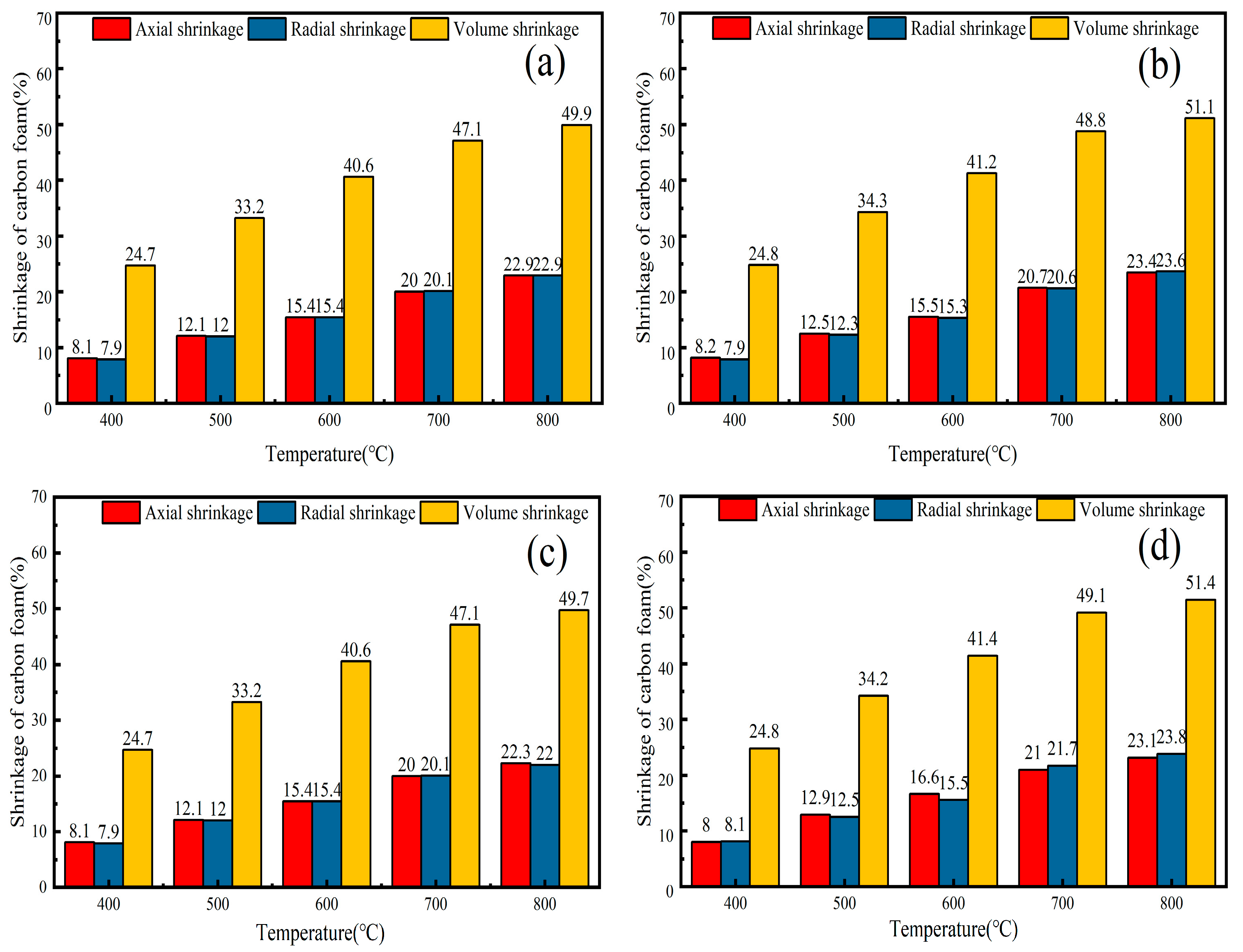
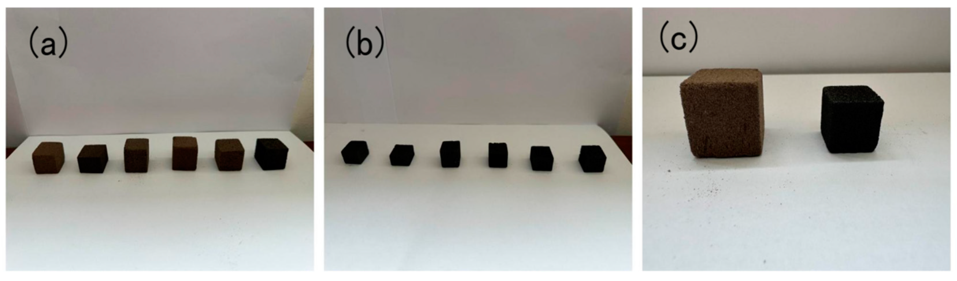
3.1. Carbonization Temperature Effects on Carbon Foam Volume Stability
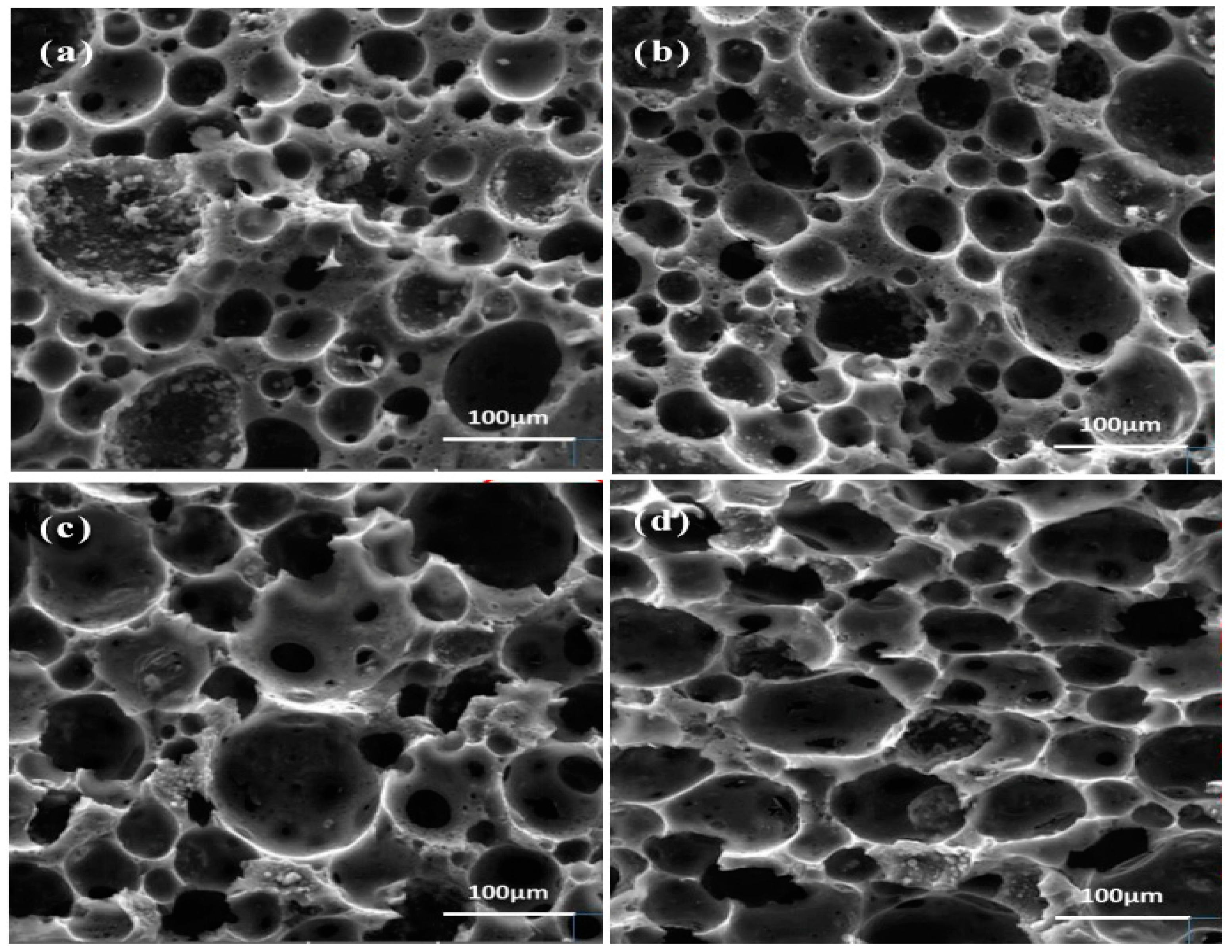
3.2. Structural Characterization and Physicochemical Properties of Carbon Foams
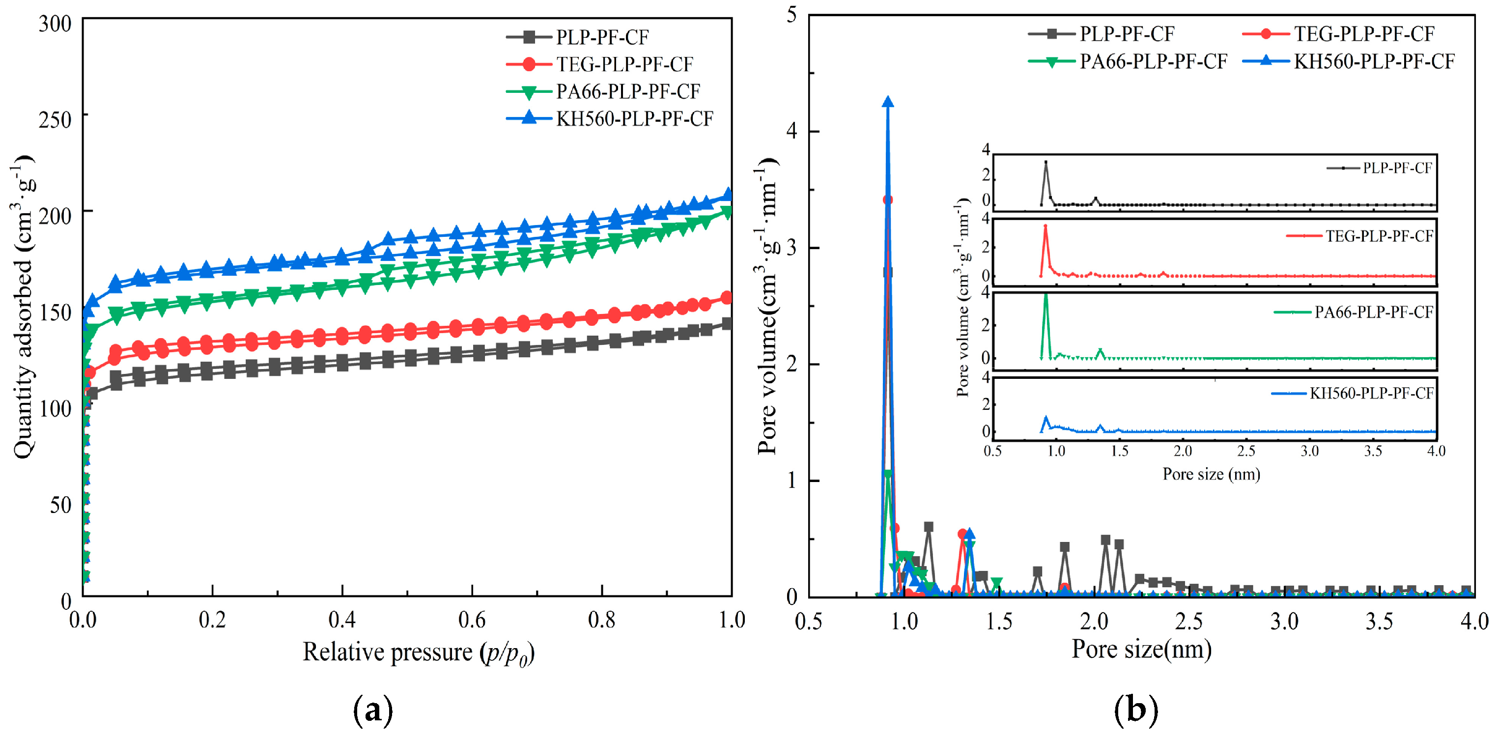
3.3. Analysis of Specific Surface Area, Pore Volume, and Micropore Size of Carbon Foams
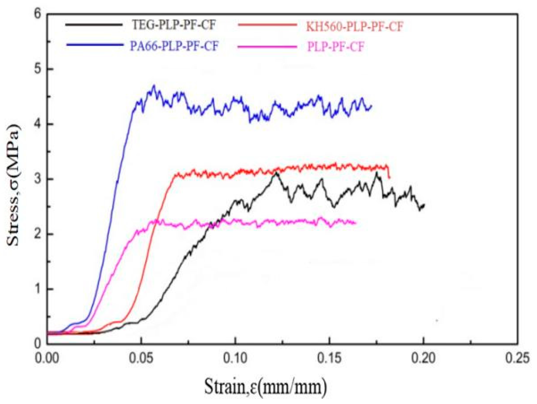
3.4. Mechanical Properties of Carbon Foams
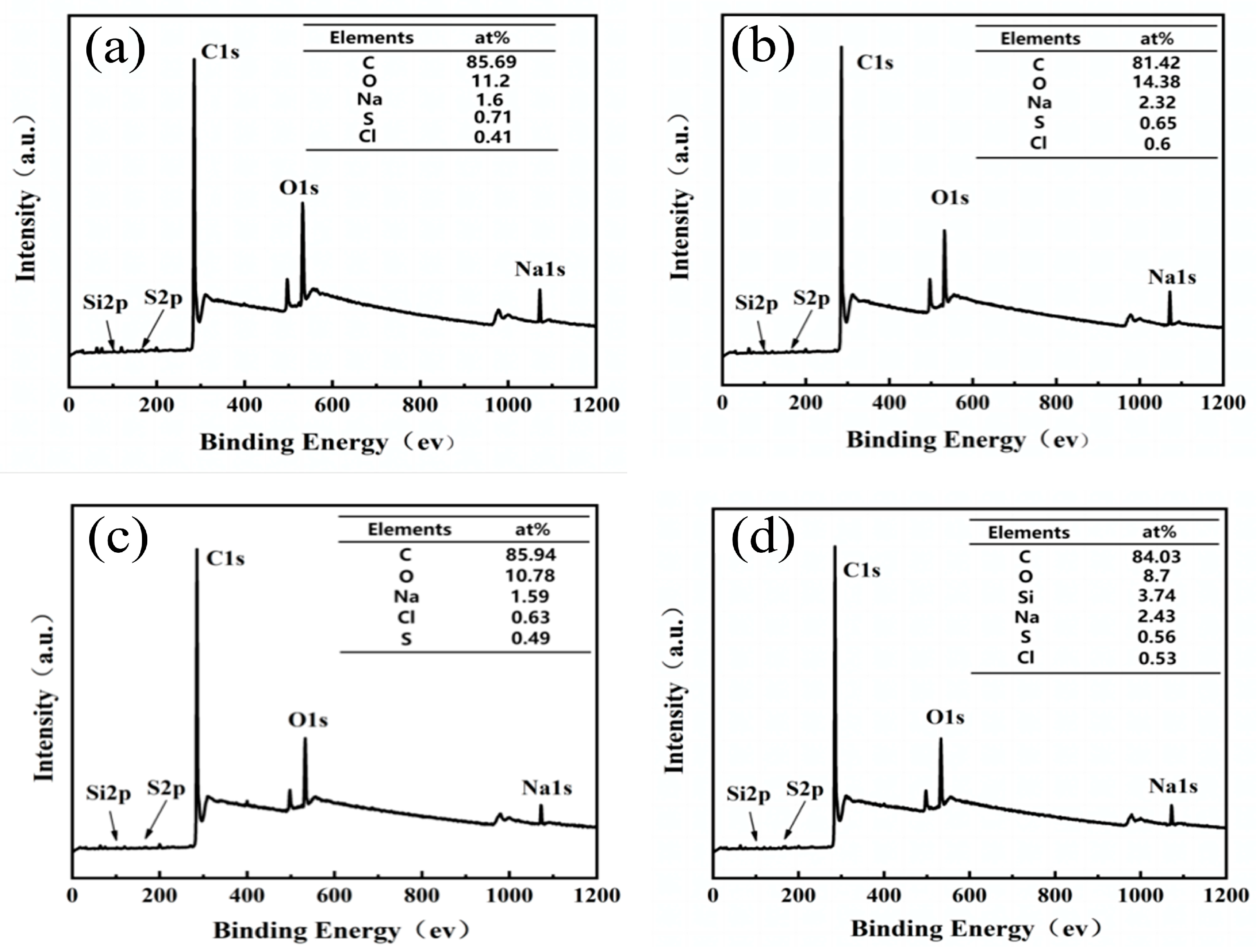
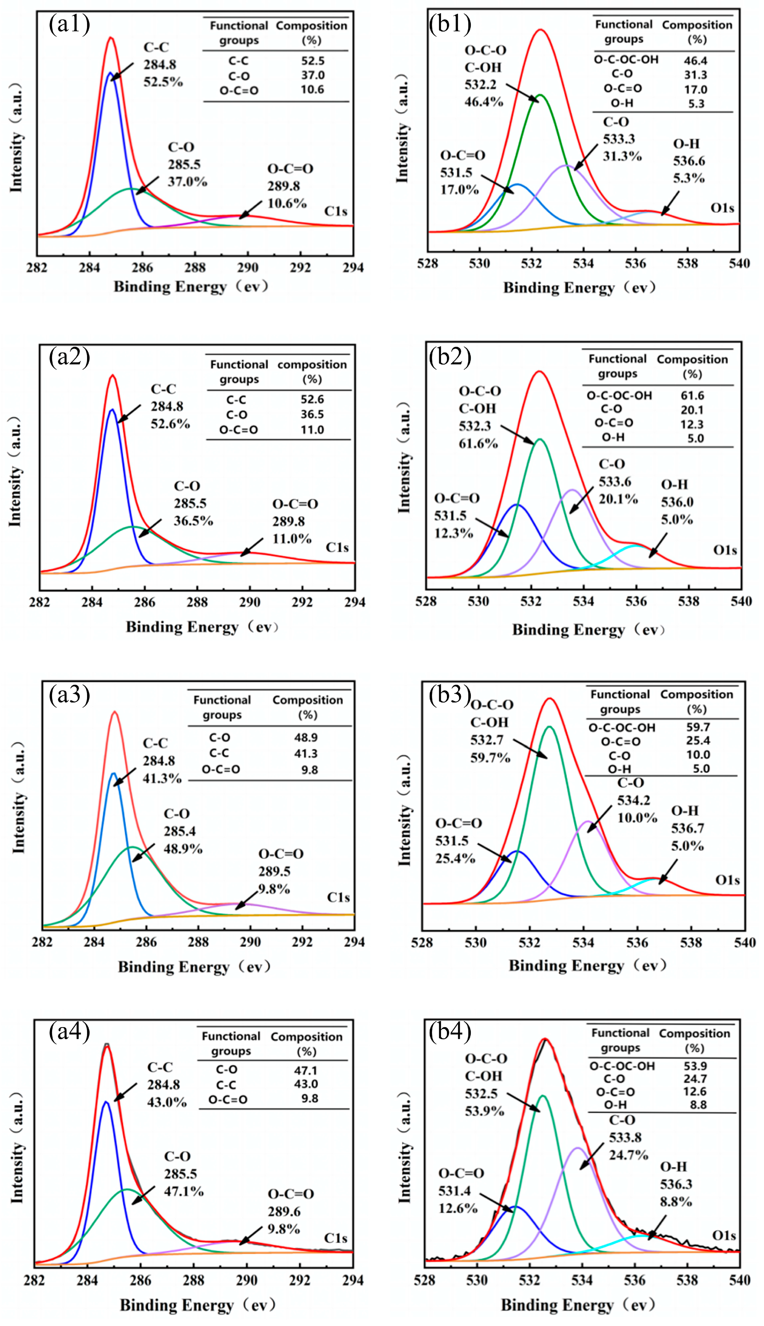
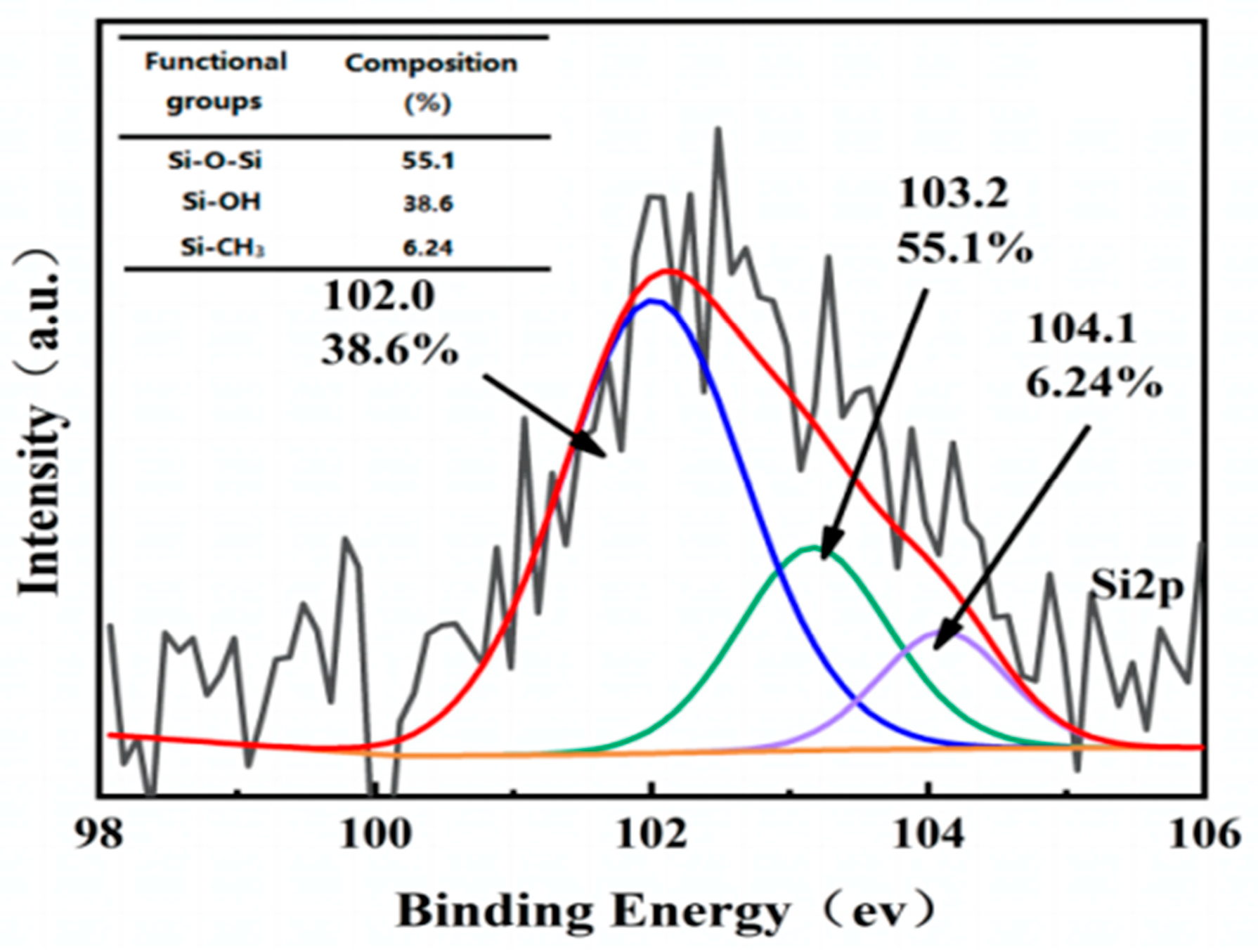
3.5. XPS Analysis
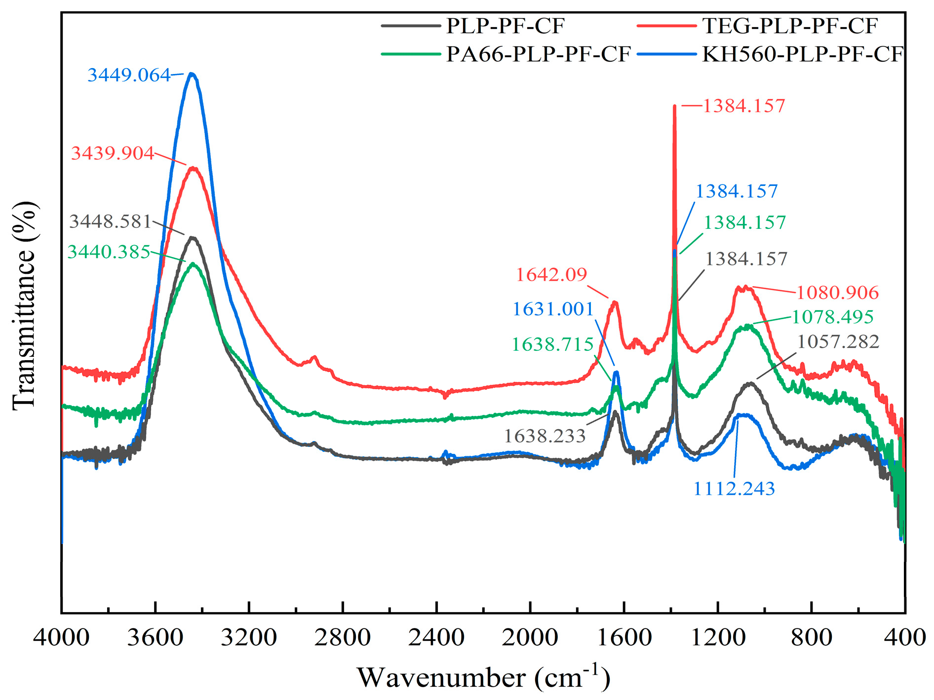
3.6. FT-IR Analysis
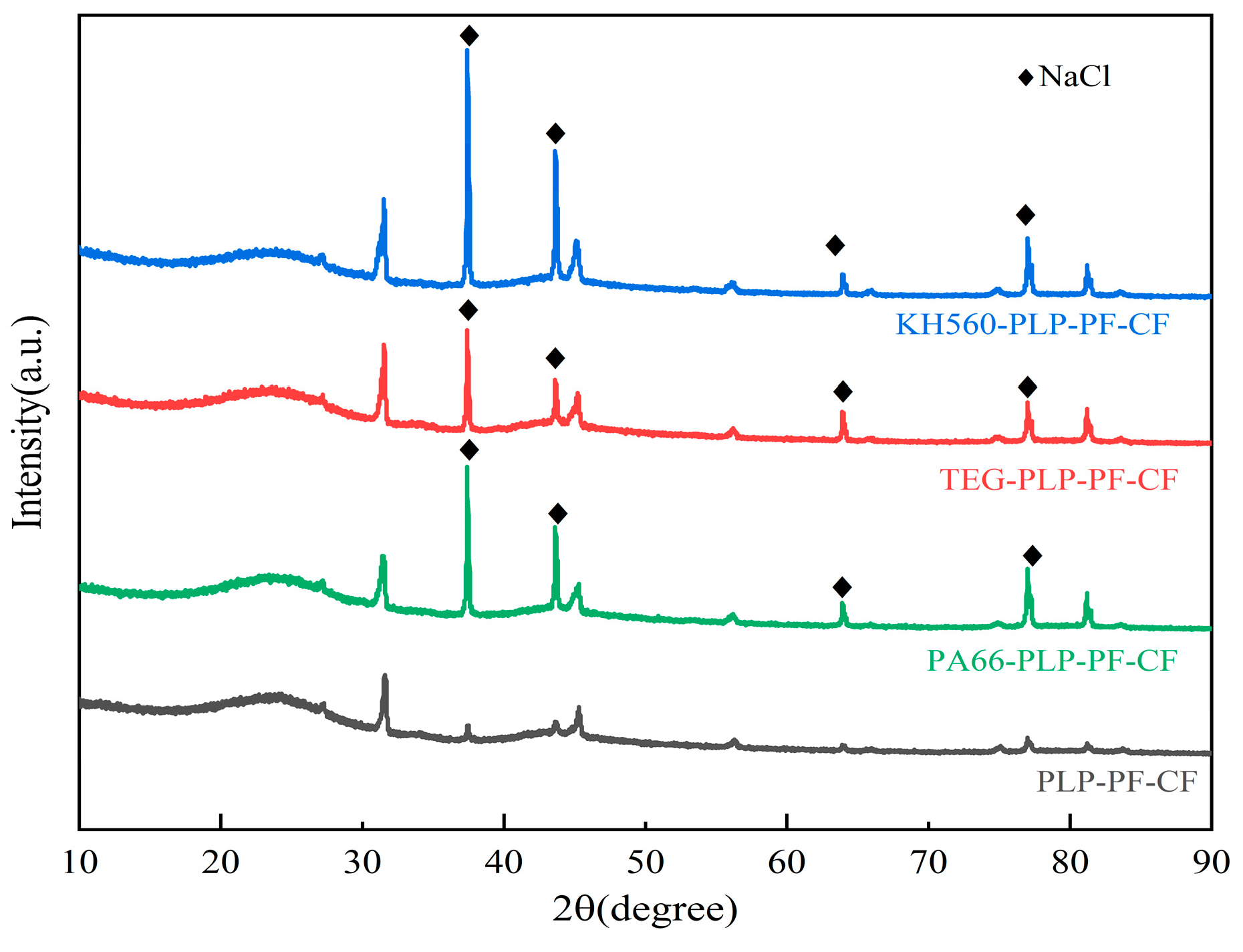
3.7. XRD Analysis of Carbon Foams
4. Conclusions
Author Contributions
Funding
Data Availability Statement
Conflicts of Interest
References
- Ge, L.; Zhao, C.; Zuo, M.; Tang, J.; Ye, W.; Wang, X.; Zhang, Y.; Xu, C. Review on the preparation of high value-added carbon materials from biomass. J. Anal. Appl. Pyrolysis 2022, 168, 105747. [Google Scholar] [CrossRef]
- Zhang, B.; Jiang, Y.; Balasubramanian, R. Synthesis of biowaste-derived carbon foam for CO2 capture. Resour. Conserv. Recycl. 2022, 185, 106453. [Google Scholar] [CrossRef]
- Gou, G.; Huang, F.; Jiang, M.; Li, J.; Zhou, Z. Hierarchical porous carbon electrode materials for supercapacitor developed from wheat straw cellulosic foam. Renew. Energy 2020, 149, 208–216. [Google Scholar] [CrossRef]
- Liu, H.; Wu, S.; Tian, N.; Yan, F.; You, C.; Yang, Y. Carbon foams: 3D porous carbon materials holding immense potential. J. Mater. Chem. A 2020, 8, 23699–23723. [Google Scholar] [CrossRef]
- Cao, M.; Feng, Y.; Tian, R.; Chen, Q.; Chen, J.; Jia, M.; Yao, J. Free-standing porous carbon foam as the ultralight and flexible supercapacitor electrode. Carbon 2020, 161, 224–230. [Google Scholar] [CrossRef]
- Yang, N.; Ji, L.; Fu, H.; Shen, Y.; Wang, M.; Liu, J.; Chang, L.; Lv, Y. Hierarchical porous carbon derived from coal-based carbon foam for high-performance supercapacitors. Chin. Chem. Lett. 2022, 33, 3961–3967. [Google Scholar] [CrossRef]
- Ola, O.; Chen, Y.; Zhu, Y. Three-dimensional carbon foam nanocomposites for thermal energy storage. Sol. Energy Mater. Sol. Cells 2019, 191, 297–305. [Google Scholar] [CrossRef]
- Qi, J.; Wei, G.; Sun, X.; Wang, L.; Li, J. Enhanced removal for H2S by Cu-ordered mesoporous carbon foam. J. Hazard. Mater. 2020, 396, 122710. [Google Scholar] [CrossRef] [PubMed]
- Licona-Aguilar, A.I.; Torres-Huerta, A.M.; Dominguez-Crespo, M.A.; Palma-Ramirez, D.; Conde-Barajas, E.; Negrete-Rodriguez, M.X.L.; Rodriguez-Salazar, A.E.; Garcia-Zaleta, D.S. Reutilization of waste biomass from sugarcane bagasse and orange peel to obtain carbon foams: Applications in the metal ions removal. Sci. Total Environ. 2022, 831, 154883. [Google Scholar] [CrossRef] [PubMed]
- Lyu, L.; Zheng, S.; Wang, F.; Liu, Y.; Liu, J. High-performance microwave absorption of MOF-derived Co3O4@N-doped carbon anchored on carbon foam. J. Colloid Interface Sci. 2021, 602, 197–206. [Google Scholar] [CrossRef]
- Varila, T.; Mäkelä, E.; Kupila, R.; Romar, H.; Hu, T.; Karinen, R.; Puurunen, R.L.; Lassi, U. Conversion of furfural to 2-methylfuran over CuNi catalysts supported on biobased carbon foams. Catal. Today 2021, 367, 16–27. [Google Scholar] [CrossRef]
- Wang, T.; Zhu, C.; Song, L.; Du, P.; Yang, Y.; Xiong, J. A facile controllable preparation of highly porous carbon foam and its application in photocatalysis. Mater. Res. Bull. 2020, 122, 110697. [Google Scholar] [CrossRef]
- Alifanov, O.M.; Budnik, S.A.; Nenarokomov, A.V.; Salosina, M.O. Design of thermal protection based on open cell carbon foam structure optimization. Appl. Therm. Eng. 2020, 173, 115252. [Google Scholar] [CrossRef]
- Wang, C.; Peng, L.; Shi, Z.-h.; Li, B.-l.; Li, K.-z. Preparation, thermal stability and deflection of a density gradient thermally-conductive carbon foam material derived from phenolic resin. Results Phys. 2019, 14, 102448. [Google Scholar]
- Yu, M.; Ao, X.; Chen, Q. Fabrication of ultralight reticulated carbon foams for thermal insulation from raffinate pitch of low-temperature coal tar. J. Anal. Appl. Pyrolysis 2022, 163, 105494. [Google Scholar] [CrossRef]
- Ge, C.; Song, J.; Qin, Z.; Wang, J.; Fan, W. Polyurethane Foam-Based Ultramicroporous Carbons for CO2 Capture. ACS Appl. Mater. Interfaces 2016, 8, 18849–18859. [Google Scholar] [CrossRef] [PubMed]
- Rodríguez, E.; Diez, M.A.; Antuña-Nieto, C.; López-Antón, M.A.; García, R.; Martínez-Tarazona, M.R. An insight into the role of biomass, biocompounds and synthetic polymers as additives to coal for the synthesis of carbon foams. J. Anal. Appl. Pyrolysis 2021, 160, 105359. [Google Scholar] [CrossRef]
- Zhang, Y.; Sun, J.; Tan, J.; Ma, C.; Luo, S.; Li, W.; Liu, S. Hierarchical porous graphene oxide/carbon foam nanocomposites derived from larch for enhanced CO2 capture and energy storage performance. J. CO2 Util. 2021, 52, 101666. [Google Scholar] [CrossRef]
- Sun, L.; Wan, S.; Yuan, D.; Yu, Z. Adsorption of nitroimidazole antibiotics from aqueous solutions on self-shaping porous biomass carbon foam pellets derived from Vallisneria natans waste as a new adsorbent. Sci. Total Environ. 2019, 664, 24–36. [Google Scholar] [CrossRef] [PubMed]
- Qu, W.; Zhao, Z.; Liang, C.; Hu, P.; Ma, Z. Simple, additive-free, extra pressure-free process to direct convert lignin into carbon foams. Int. J. Biol. Macromol. 2022, 209, 692–702. [Google Scholar] [CrossRef]
- Liang, C.; Xia, H.; Yin, L.; Du, C.; Wu, X.; Wang, J.; Li, S.; Xu, J.; Zhang, X.; Wang, Y.; et al. Carbon foam directly synthesized from industrial lignin powder as featured material for high efficiency solar evaporation. Chem. Eng. J. 2024, 481, 148375. [Google Scholar] [CrossRef]
- Lin, F.; Zhang, X.; Liu, X.; Xu, Y.; Sun, Z.; Zhang, L.; Huang, Z.; Mi, R.; Min, X. Polyethylene glycol/modified carbon foam composites for efficient light-thermal conversion and storage. Polymer 2021, 228, 123894. [Google Scholar] [CrossRef]
- Wang, K.; Li, Y.; Zhang, K.; Liu, H.; Luo, B.; Lin, Q. Preparation of near net-shape carbon foams from allyl COPNA-modified bismaleimide resin: Structures and properties. J. Anal. Appl. Pyrolysis 2016, 117, 125–131. [Google Scholar] [CrossRef]
- Song, W.; Cui, S.; Zhang, J.; Fan, S.; Chen, L.; Zhang, H.M.; Zhang, Y.; Meng, X. Three-Dimensional Carbon Foam Modified with Mg3N2 for Ultralong Cyclability of a Dendrite-Free Li Metal Anode. ACS Appl. Mater. Interfaces 2023, 15, 9421–9430. [Google Scholar] [CrossRef] [PubMed]
- Wang, J.; Khan, M.; Hussain, A.; Khan, I.; Nawaz, A.; Ragab, A.H.; Sayqal, A.; Lei, T.; Zada, A. Carbon foam composites containing carbon nanotubes and graphene oxide as additives for enhanced mechanical, thermal, electrical and catalytic properties. J. Mater. Res. Technol. 2023, 24, 608–622. [Google Scholar] [CrossRef]
- Bhanuprakash, L.; Parasuram, S.; Varghese, S. Experimental investigation on graphene oxides coated carbon fibre/epoxy hybrid composites: Mechanical and electrical properties. Compos. Sci. Technol. 2019, 179, 134–144. [Google Scholar] [CrossRef]
- Li, H.; Li, T.; Deng, W.; Kong, S. Preparation and Adsorption Properties of Graphene-Modified, Pitch-Based Carbon Foam Composites. Polymers 2022, 14, 4455. [Google Scholar] [CrossRef]
- Xie, Y.; Xiao, S.; Chen, W.; Hu, X.; Liu, Y.; Jiang, L.; Luo, L.; Luo, W.; Ma, Y.; Jiang, X.; et al. Shape-stabilized nanosilver-modified grapefruit peel-based porous carbon composite phase change material with high thermal conductivity, photothermal conversion performance and thermal management capability. J. Energy Storage 2024, 83, 110819. [Google Scholar] [CrossRef]
- Tang, K.; Tang, X.; Liu, X.; Zhang, A.; Ge, T.; Li, Y. Phenolic Foams Toughened with Triethylene Glycol by In Situ Polymerization and Prepolymerization Processes. ACS Appl. Polym. Mater. 2022, 4, 8303–8314. [Google Scholar] [CrossRef]
- Zhang, Y.L.; Zang, C.G.; Jiao, Q.J. Electrical, thermal, and mechanical properties of silicone foam composites filled with carbon-based nanofillers. J. Appl. Polym. Sci. 2020, 137, 49191. [Google Scholar] [CrossRef]
- Wang, Y.; Chen, Z.; Yang, L.; Xu, T.; Wu, H.; Zhang, J.; He, L. Effect of pre-heat treatment and carbonization temperature on comprehensive properties of melamine-derived carbon foam. Ceram. Int. 2024, 50, 31548–31558. [Google Scholar] [CrossRef]
- Banerjee, C.; Chandaliya, V.K.; Dash, P.S.; Meikap, B.C. Effect of different parameters on porosity and compressive strength of coal tar pitch derived carbon foam. Diamond Relat. Mater. 2019, 95, 83–90. [Google Scholar] [CrossRef]
- Nagel, B.; Pusz, S.; Trzebicka, B. Tailoring the properties of macroporous carbon foams. J. Mater. Sci. 2014, 49, 1–17. [Google Scholar] [CrossRef]
- Seo, J.; Park, H.; Shin, K.; Baeck, S.H.; Rhym, Y.; Shim, S.E. Lignin-derived macroporous carbon foams prepared by using poly (methyl methacrylate) particles as the template. Carbon 2014, 76, 357–367. [Google Scholar] [CrossRef]
- Wu, H.; Pu, X.; Li, X.; Li, T.; Jiang, S.; Liu, S. Self-foaming calcium modified carbon foam derived from a liquefied product resin of tobacco stalks for the removal of Pb2+ in water. Ind. Crop. Prod. 2024, 216, 118743. [Google Scholar] [CrossRef]
- Farhan, S.; Wang, R.; Jiang, H.; Li, K.; Wang, C. A novel combination of simple foaming and freeze-drying processes for making carbon foam containing multiwalled carbon nanotubes. Ceram. Int. 2016, 42, 8980–8989. [Google Scholar] [CrossRef]
- Narasimman, R.; Prabhakaran, K. Preparation of carbon foams by thermo-foaming of activated carbon powder dispersions in an aqueous sucrose resin. Carbon 2012, 50, 5583–5593. [Google Scholar] [CrossRef]
- Ji, H.; Huang, Z.; Wu, X.; Huang, J.; Chen, K.; Fang, M.; Liu, Y. Preparation, microstructure, and compressive strength of carbon foams derived from sucrose and kaolinite. J. Mater. Res. 2014, 29, 1018–1025. [Google Scholar] [CrossRef]
- Jana, P.; Fierro, V.; Celzard, A. Sucrose-based carbon foams with enhanced thermal conductivity. Ind. Crop. Prod. 2016, 89, 498–506. [Google Scholar] [CrossRef]
- Zhang, Q.; Du, Z.; Guo, T.; Huang, X.; Zhu, T.; Tang, X.-Z. Three-dimensional carbon foam modified with starlike-ZnO@ reduced graphene oxide for microwave absorption with low filler content. J. Alloys Compd. 2022, 897, 163200. [Google Scholar] [CrossRef]
- Liu, Y.; Zhang, M.; Liu, D.; Gai, L.; Wang, Y.; Wang, P.; Han, X.; Du, Y. A Self-foaming Strategy to Construct Small Mo2C Nanoparticles Decorated 3D Carbon Foams as Superior Electromagnetic Wave Absorbing Materials with Strong Corrosion Resistance. Small Methods 2024, 9, 2400734. [Google Scholar] [CrossRef] [PubMed]
- Liu, J.; Wang, Z.; Li, S.; Wang, D.; Zheng, Z. Rational design of freestanding and high-performance thick electrode from carbon foam modified with polypyrrole/polydopamine for supercapacitors. Chem. Eng. J. 2022, 447, 137562. [Google Scholar] [CrossRef]
- Zhang, R.; Gu, X.; Liu, Y.; Hua, D.; Shao, M.; Gu, Z.; Wu, J.; Zheng, B.; Zhang, W.; Li, S.; et al. Hydrophilic nano-porous carbon derived from egg whites for highly efficient capacitive deionization. Appl. Surf. Sci. 2020, 512, 145740. [Google Scholar] [CrossRef]
- Zhang, Q.; Wu, R.; Zhou, Y.; Lin, Q.; Fang, C. A novel surface-oxidized rigid carbon foam with hierarchical macro-nanoporous structure for efficient removal of malachite green and lead ion. J. Mater. Sci. Technol. 2022, 103, 15–28. [Google Scholar] [CrossRef]
- Laksaci, H.; Khelifi, A.; Trari, M.; Addoun, A. Synthesis and characterization of microporous activated carbon from coffee grounds using potassium hydroxides. J. Clean. Prod. 2017, 147, 254–262. [Google Scholar] [CrossRef]
- Song, M.-X.; Xie, L.-J.; Cheng, J.-Y.; Yi, Z.-L.; Song, G.; Jia, X.-Y.; Chen, J.-P.; Guo, Q.-G.; Chen, C.-M. Insights into the thermochemical evolution of maleic anhydride-initiated esterified starch to construct hard carbon microspheres for lithium-ion batteries. J. Energy Chem 2022, 66, 448–458. [Google Scholar] [CrossRef]
- Li, C.-P.; Wu, Y.-Q.; An, J.-J.; Gao, L.-X.; Zhang, D.-Q.; Li, J.; An, Z.-X. Preparation of carbon foam from depolymerization-reforming lignin for capacitive deionization. Desalination 2023, 559, 116656. [Google Scholar] [CrossRef]
- Song, G.; Fan, W.; Zhang, J.; Xue, T.; Shi, Y.; Sun, Y.; Ding, G. Adsorption of anionic dyes from aqueous solutions by a novel CTAB/MXene/carbon nanotube composite: Characterization, experiments, and theoretical analysis. Appl. Surf. Sci. 2024, 661, 160036. [Google Scholar] [CrossRef]
- Wang, Y.; Wang, L.; Li, Z.; Yang, D.; Xu, J.; Liu, X. MgO-laden biochar enhances the immobilization of Cd/Pb in aqueous solution and contaminated soil. Biochar 2021, 3, 175–188. [Google Scholar] [CrossRef]
- Jana, P.; Fierro, V.; Pizzi, A.; Celzard, A. Biomass-derived, thermally conducting, carbon foams for seasonal thermal storage. Biomass Bioenergy 2014, 67, 312–318. [Google Scholar] [CrossRef]
- Liu, X.; Wang, Y.; Zhan, L. Carbon foams prepared from coal tar pitch for building thermal insulation material with low cost. Chin. J. Chem. Eng. 2018, 26, 415–420. [Google Scholar] [CrossRef]
- Kim, J.; Lee, J.; Hyeon, T. Direct synthesis of uniform mesoporous carbons from the carbonization of as-synthesized silica/triblock copolymer nanocomposites. Carbon 2004, 42, 2711–2719. [Google Scholar] [CrossRef]

| Samples | Cell Size (μm) | Average Cell Size (μm) | Open Porosity a (%) | pHPZC | Water Contact Angle (°) | ρ (g/cm3) |
|---|---|---|---|---|---|---|
| PLP-PF-CF | 15–126 | 45 | 70.66 | 7.76 | 117.8 | 0.275 |
| TEG-PLP-PF-CF | 27–110 | 51 | 78.13 | 7.49 | 115.8 | 0.252 |
| PA66-PLP-PF-CF | 40–140 | 78 | 79.18 | 7.45 | 124.5 | 0.250 |
| KH560-PLP-PF-CF | 40–146 | 82 | 87.95 | 7.48 | 122.0 | 0.221 |
| Samples | SBET a (m2/g) | Vtotal b (cm3/g) | Vmicro c (cm3/g) | Dpore d (μm) |
|---|---|---|---|---|
| PLP-PF-CF | 354.0 | 0.2129 | 0.1514 | 115.41 |
| TEG-PLP-PF-CF | 383.4 | 0.2336 | 0.1721 | 100.44 |
| PA66-PLP-PF-CF | 471.0 | 0.3133 | 0.2211 | 102.51 |
| KH560-PLP-PF-CF | 499.3 | 0.2995 | 0.1958 | 118.54 |
| Samples | Volume Shrinkage Rate (%) | Compressive Strength (MPa) | Apparent Density (Front) (g/cm3) | Apparent Density (Back) (g/cm3) |
|---|---|---|---|---|
| PLP-PF-CF | 47.1 | 1.79 | 0.3643 | 0.1804 |
| TEG-PLP-PF-CF | 48.8 | 2.46 | 0.1743 | 0.1416 |
| PA66-PLP-PF-CF | 48.9 | 2.61 | 0.1747 | 0.1417 |
| KH560-PLP-PF-CF | 49.1 | 3.40 | 0.1759 | 0.1546 |
| Modifiers | Additive Quantity (%) | Compressive Strength (After) (MPa) | Compressive Strength (Before) (MPa) | Literatures |
|---|---|---|---|---|
| Calcium oxide | 3 | 2.20 | 3.3 | [35] |
| Carbon nanotube | 1.5 | 1.45 | 1.10 | [36] |
| Activated carbon | 10 | 3.40 | 1.1 | [37] |
| Kaolinite clay | 15 | 0.21 | 0.08 | [38] |
| Graphite powder | 9 | 4.5 | 0.53 | [39] |
Disclaimer/Publisher’s Note: The statements, opinions and data contained in all publications are solely those of the individual author(s) and contributor(s) and not of MDPI and/or the editor(s). MDPI and/or the editor(s) disclaim responsibility for any injury to people or property resulting from any ideas, methods, instructions or products referred to in the content. |
© 2025 by the authors. Licensee MDPI, Basel, Switzerland. This article is an open access article distributed under the terms and conditions of the Creative Commons Attribution (CC BY) license (https://creativecommons.org/licenses/by/4.0/).
Share and Cite
Lu, S.; Ling, J.; Liu, S.; Li, X.; Liu, J. Structural Properties of a Novel Modified Carbon Foam Derived from Pine Sawdust. Forests 2025, 16, 311. https://doi.org/10.3390/f16020311
Lu S, Ling J, Liu S, Li X, Liu J. Structural Properties of a Novel Modified Carbon Foam Derived from Pine Sawdust. Forests. 2025; 16(2):311. https://doi.org/10.3390/f16020311
Chicago/Turabian StyleLu, Shiyu, Jianwei Ling, Shouqing Liu, Xuemei Li, and Jianxiang Liu. 2025. "Structural Properties of a Novel Modified Carbon Foam Derived from Pine Sawdust" Forests 16, no. 2: 311. https://doi.org/10.3390/f16020311
APA StyleLu, S., Ling, J., Liu, S., Li, X., & Liu, J. (2025). Structural Properties of a Novel Modified Carbon Foam Derived from Pine Sawdust. Forests, 16(2), 311. https://doi.org/10.3390/f16020311