Abstract
Indium and its compounds have many industrial applications and are widely used in the manufacture of liquid crystal displays, semiconductors, low temperature soldering, and infrared photodetectors. Indium does not have its own minerals in the Earth’s crust, and most commonly, indium is associated with the ores of zinc, lead, copper and tin. Therefore, it must be recovered as a by-product from other metallurgical processes or from secondary raw materials. The aim of this study is to investigate the adsorption properties for recovering indium from aqueous solutions using iron–magnesium composite (MgFe2O4). In addition, the results show that the material offers very efficient desorption in 15% HCl solution, being used for 10 adsorption–desorption cycle test. These results provide a simple and effective process for recovering indium. Present study was focuses on the synthesis and characterization of the material by physico-chemical methods such as: X-ray diffraction, FT-IR spectroscopy, followed by the adsorption tests. The XRD indicates that the MgFe2O4 phase was obtained, and the crystallite size was about 8 nm. New prepared adsorbent materials have a point of zero charge of 9.2. Studies have been performed to determine the influence of pH, initial indium solution concentration, material/solution contact time and temperature on the adsorption capacity of the material. Adsorption mechanism was established by kinetic, thermodynamic and equilibrium studies. At equilibrium a maximum adsorption capacity of 46.4 mg/g has been obtained. From kinetic and thermodynamic studies was proved that the studied adsorption process is homogeneous, spontaneous, endothermic and temperature dependent. Based on Weber and Morris model, we can conclude that the In (III) ions takes place at the MgFe2O4/In (III) solution–material interface.
1. Introduction
Indium and its compounds have widespread industrial applications in several fields [1,2]. The European Union included indium into the list of critical materials. China was reported as one the largest producers of indium in the word, reaching a total of 290 tons in 2016. For example, in 2009 about 110 tons of indium were consumed in the US, and indium consumption increases annually [1,2,3,4,5,6]. Massive development of mobile electronic devices requires a large consumption of In, used in the form of indium–tin–oxide layers into LCD construction [7]. Different estimations indicate that into the Earth’s crust indium content ranges from 50 to 200 parts per billion [8]. However, at the present consumption rate indium reserves are expected to be depleted in 20 years, and the demand and consumption of indium increases every year [9,10]. Until now, different attempts were made for In recovery from different scraps [7]. Therefore, the development of an efficient recovery process is extremely important for the stable supply of indium, along with the issue of resource recycling and environmental sustainability [11,12,13].
Conventional methods for recovering indium from secondary resources (such as industrial wastewater), include precipitation [2,14,15], solvent extraction [16], ion exchange [2,10,17,18,19,20,21], nanofiltration membranes [2,22], chemical reduction [2,23], and electroanalytical techniques [2,24]. Solvent precipitation and solvent extraction are well-known recovery methods, but they generate potential environmental problems caused by the usage of large amounts of chemicals and organic solvents [17]. However, the principal disadvantage of the solvent extraction process is represented by extractant loss, which can cause environmental hazards concomitant with economic constraints. Compared to solvent extraction, ion exchange technique is much easier. However, its low selectivity for desired metallic ions represents the main problem of such a recovery technique. Recently, the usage of impregnated resins was developed as a technological alternative for indium ion extraction [10,25,26,27,28]. Other technologies used for indium recovery from aqueous solutions are solvent extraction and resin adsorption. In order to attain a higher separation efficiency of indium from aqueous solutions it is recommended to use multi-step extraction/adsorption and reverse extraction/desorption. In addition, an increase in secondary waste production was observed when of organic solvent and acidic solutions introduction.
The pyrometallurgical method can be used for recovery of indium species, but it needs a large amount of energy to operate at high temperatures, and its ability to separate metals is not ideal. Electroplating has a high operability due to the controllable potential of the electrode and the adjustable electroreduction property of the metal by the addition of ligand [29,30] and demonstrated superiority in the extraction of metal from multimetallic waste.
Adsorption is expected to be the most suitable method for recovering indium due to its simple concept, high safety and ecological process [14,31,32,33,34,35]. In particular, different research studies were carried out in order to find a proper adsorbent material, with higher selectivity for indium ions. Such materials are represented by different polymeric resins, having grafted different functional groups [9,36]. Fortes et al. reported adsorption of indium in aqueous solution by means of chelating resin of iminodiacetic acid as a sorbent [2,37], and Tokuyama and Iwama studied solid phase extraction of indium using poly (N-isopropylacrylamide) as the sorbent [38]. The hydrogen ion of the iminodiacetic acid group on the polymeric resin could be replaced with the indium ions. In this way, indium ions are displaced and chelated inside the polymeric resin by the functional group [37]. Moreover, Calagui et al. [14], reported the adsorption of indium from aqueous solution on chitosan-coated bentonite balls. Therefore, numerous adsorptive processes have been developed for indium separation and recovery from different residual solutions. In such processes, various absorbents were used such as: starch, activated carbon, activated carbon clothing, fly ash, chitin, shrimp shell, peanut shell pellets, clay minerals, zeolites and resins [2,14,39,40,41,42,43,44,45,46].
In the present paper we describe the attempt of usage of magnesium ferrites spinel type structure as an adsorbent material for indium recovery. Until now, usage of MgFe2O4 spinel as adsorbent material has been very limited. The spinel-type structures of magnesium ferrites are of increasing interest due to their chemical and physical properties. The molecular structure of magnesium ferrites is found in the form of:
- Mg2+, Fe3+—divalent and trivalent cations
- X—degree of inversion
In a spinel structure, cations Mg2+ and Fe3+ can occupy tetrahedral interstitial positions (T) as well as octahedron (O) of the cubic lattice formed by ions of O2− [47]. Bloesser et al. shows that in order to obtain materials with the desired properties we have to change the degree of inversion by modifying the synthesis parameters [48]. If we change parameters such as temperature, the interstitial positions of magnesium ions can also change.
Hammache et al. indicate that the spinel MgFe2O4 is non-toxic to the environment [49]. From the data of the literature it was observed that the spinel MgFe2O4 presents a wide range of applications such as: photocatalysis [50], catalytic activity, gas sensor, electronics, battery anode, pigments, magnetic resonance imaging, hyperthermia therapy and targeted drug delivery.
Various methods can be used to obtain ferrite spinel such as sol-gel, pulse laser deposition, hydrothermal [49], coprecipitation [47], microemulsions, combustion metho and solid-state reaction [51]. The aim of this study is to investigate the adsorptive properties of spinel type magnesium ferrites for indium recovery from aqueous solutions.
2. Materials and Methods
2.1. Material Synthesis and Characterization
2.1.1. MgFe2O4 Composite Synthesis
MgFe2O4 composite was prepared by coprecipitation method [52]. Thus, to obtain the composite adsorbent 1 g of magnesium carbonate, MgCO3 (SC CHIMOPAR TRADING SRL, Bucharest, Romania), 30 mL of distilled water together with 30 mL of methanol (SC CHIMOPAR TRADING SRL, Bucharest, Romania) were contacted, mixed for 1 h and then 5 mL of HNO3 solution (SC CHIMOPAR TRADING SRL, Bucharest, Romania) was added to reach a pH between 1.5 and 2. The HNO3 solution is made by adding 5 mL of concentrated HNO3 and 245 mL of distilled water. After another half hour, the iron (III) nitrate, Fe (NO3)3 (SC CHIMOPAR TRADING SRL, Bucharest, Romania) was added, the temperature raised to 50 °C and the solution was stirred until it was homogenous, after about 3 h. To precipitate the material at the end, ~10 mL of NaOH solution (Merck, Sigma Aldrich, Munchen, Germany) was added to increase the pH to 5. The NaOH solution was made by adding 7.5 g of NaOH beads in 100 mL of distilled water. After obtaining the precipitate, the supernatant was removed. To remove Na from the compound it was washed with excess water. The material was dried for 24 °C to 100 °C in an oven (Pol-eko model SLW 53, SDT, Rybnik, Poland), then calcined at 260 °C in an oven at a speed of 5°/min, using an oven with controlled air atmosphere (Nabertherm LHT407GN Furnaces, Lilienthal, Germany).
2.1.2. MgFe2O4 Composite Physico-Chemical Characterization
Thermogravimetric Analysis, DTG
The differential thermal analysis, DTG, was performed to highlight the temperature dependence of the physical properties, using a TGA/SDTA 851-LF Mettler-Toledo. The decomposition was performed in the presence of air and the sample was heat treated in the range of 25–900 °C.
Fourier Transform Infra-Red Spectroscopy, FT-IR
The material was characterized by Fourier transform infrared spectroscopy (FT-IR) by using a JASCO FT/IR-4200 apparatus (SpectraLab, Shimadzu, Japan).
X-ray Diffraction Analysis, XRD
In order to obtain information about the degree of crystallinity of the material and the presence of several phases in the material, X-ray diffraction analysis was performed, XRD (D8 Advance-Bruker AXS), using Mo-Kα radiation (αMo = 0.7093 Å).
pHpZc
Point of zero charge, pHpZc, was determined by bringing the studied system to equilibrium. In this case, 0.1 g of adsorbent material (MgFe2O4) wZ mixed with 25 mL of 0.1 N KCl solution at 200 rpm and a temperature of 298 K, using a water bath with thermostating and stirring, Julabo SW23 type. KCl solutions pH was modified in range 2–12, by adding NaOH solutions with a concentration between 0.05 N and 2 N or HNO3 solutions with a concentration between 0.05 N and 2 N. Further, all the samples were filtered and subsequently was determined the pH of the resulting solution by using a pH meter (METTLER TOLEDO, SevenCompact, S 210 type).
2.1.3. Adsorption Studies
pH Effect
In the present paper we studied the influence of pH on the adsorption process of In (III) on the synthesized material, varying the pH, in the range 1–14. Thus, 0.1 g of material was kept in contact with 25 mL of In (III) solution (InCl3, 99.995% purity, ACROS organics, India) of initial concentration, C0 = 100 µg L−1, for 60 min in a JUABO type thermostatic bath (SW 23), at a temperature of 298 K. The pH of the solutions was adjusted using HNO3 and NaOH solutions having concentrations in the range of 0.1–1 N, obtained by diluting 63% HNO3 (Carl Roth) and NaOH, pellets (Merck Sigma Aldrich).
Contact Time and Temperature Effect
In order to establish the influence of contact time and temperature on material adsorption capacity, 0.1 g of adsorbent material were weighed and mixed with a 25 mL solution containing 100 µg L−1 In (III). Different samples were prepared, which were mixed for different times (15, 30, 60 and 120 min), at different temperatures (298, 308, 318 and 328 K) and 200 rpm using a thermostatic bath.
Initial Concentration Effect
In order to establish the effect of the initial concentration of In (III) ions on the adsorption capacity of the MgFe2O4 adsorbent material, solutions with concentrations of 5 × 10², 1 × 10³, 1,5 × 10³, 2 × 10³, 3 × 10³, 5 × 10³, 7 × 10³, 8 × 10³, 1 × 10⁴, 5 × 10⁴, 1 × 10⁵, 2 × 10⁵ and 3 × 10⁵ µg L−1 were prepared. These solutions were prepared by appropriate dilution from a stock solution of InCl3, 1000 mg L−1. All adsorption tests were conducted at pH > 2 for 90 min and at 298 K. In order to evaluate the adsorption capacity was measured the residual concentration of In (III), by using the graphite furnace atomic absorption spectrophotometer (AA 6800, Schimadzu).
Kinetics Adsorption
In order to study the adsorption kinetic for studied adsorption process obtained experimental data were modelled with three different kinetic models: Lagergren, Ho and McKay, and Weber and Morris one. Equations used to describe adsorption kinetic are presented in Table 1.

Table 1.
Equations used to describe adsorption kinetics.
Adsorption Isotherm Models
Similar, in order to better understand and describe the adsorption equilibrium, experimental data were modelled using Langmuir, Freundlich and Sips isotherms. Equations used to describe adsorption equilibrium are presented in Table 2.
Table 2.
Equations used to describe adsorption equilibrium.
Thermodynamic Studies
The amount of activation energy, Ea, provides information about the nature of the adsorption process whether it is physical or chemical. Further, starting from the experimental data obtained for In (III) adsorption on the prepared adsorbent, we evaluated the activation energy based on the Arrhenius equation:
where:
- k2—speed constant (g min−1 mg−1)
- A—Arrhenius constant (g min mg−1)
- Ea—activation energy (kJ mol−1)
- T—absolute temperature (K)
- R—ideal gas constant (8.314 J mol−1 k−1).
Taking in account that the pseudo-second-order model is better fitting obtained experimental data, the activation energy was calculated by using the speed constant obtained based on this model. Based on the slope of the linear dependence lnk2 versus 1/T, was determined the value of activation energy.
Further, based on Gibbs–Helmholtz equation was calculated the value of Gibbs energy, used to establish if the In (III) adsorption onto the prepared adsorbent material is a spontaneous process [33]:
where:
- ΔG°—free Gibbs energy standard variation (J mol−1)
- ΔH°—enthalpy standard variation (J mol−1)
- ΔS°—entropy standard variation (J mol−1 k−1)
- T—absolute temperature (K)
Standard variations of enthalpy and entropy were evaluated from linear dependence of ln Kd versus 1/T (linear form of van’t Hoff equation), where Kd is the equilibrium constant, which was calculated as ratio between equilibrium adsorption capacity (qe) and equilibrium concentration (Ce).
3. Results and Discussion
3.1. Material Synthesis and Characterization
3.1.1. Thermogravimetric Analysis, DTG
Figure 1 shows that the material decomposes in three steps. In the first part of the process up to 200 °C there are two specific peaks associated with elimination of water and organic solvents with a mass loss of 16.35%. In the second part of the process an exothermic process takes place, attributed to iron nitrate III beginning to decompose, and NOx is formed. At the same time, the decomposition of MgCO3 and CO2 takes place [60].
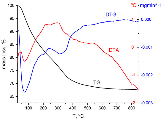
Figure 1.
Thermogravimetric analysis for MgFe2O4 material.
At this stage in the range of 200–500 °C there is a loss of 14.49% with the formation of the spinel MgFe2O4 and partially a crystalline phase of Fe3O4. In the last stage, the material has a loss of about 1.78%. At a temperature of 875 °C, the material has a plateau meaning that most of the processes have taken place.
Chemical analysis was performed after calcination of the sample up to la 900 °C indicating that Mg and Fe ions are in ideal proportions for the formation of MgFe2O4.
3.1.2. X-ray Diffraction Analysis, XRD
Figure 2 shows X-ray diffractograms for MgFe2O4 powder calcined at 260 °C.
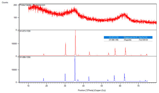
Figure 2.
XRD MgFe2O4 material treated at 260 °C.
The general appearance of the material is that it is amorphous, but following the peaks from 30, 35, 57 and 63, 2θ, which are associated with the presence of the crystalline phases 220, 311, 333 and 440, can conclude that a MgFe2O4 phase was obtained. The material corresponds to a cubic-type network, Fd-3m. The sampled data were evaluated using the reference sheet 01-073-1720 indicating that the major phase MgFe2O4. A secondary phase is formed to a small extent being specific to magnetite. Using Scherrer’s equation, the crystallite size was determined using the peaks at 311 and 440 with an average value of about 8 nm.
3.1.3. FT-IR Spectra
Figure 3 shows the FT-IR spectrum of the MgFe2O4 material, recorded into the range 4000 and 400 cm−1.
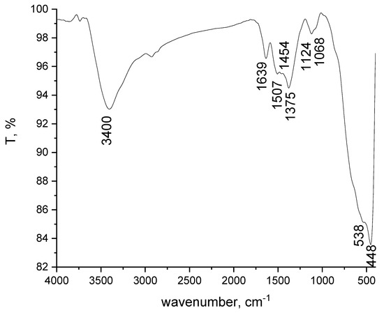
Figure 3.
FT-IR spectra of the MgFe2O4 composite.
By analysing the spectrum depicted in Figure 3 the presence of the specific bands for -OH stretching and bending vibrations are observed, located at 3400 and 1639 cm−1, respectively [47]. The 1507, 1454 and 1375 cm−1 bands specific for stretching vibration of carbon groups are also present in the spectrum. The adsorption band at 1124 and 1068 cm−1 could be attributed to the presence of nitrates ion [61].
The most important bands obtained at 538 and 448 cm−1 are specific for the formation of the spinel ferrite structure. Referring to the literature, we note that in the peak located at 448 cm−1, it is specific for octahedral Mg-O and Fe-O. In our case, the peak at 538 cm−1 shows the clear formation of spinel MgFe2O4 or/and tetrahedral Fe-O [62,63].
These absorbance bands are attributed to vibration of tetrahedral (higher energy band of M-O) and octahedral (lower frequency band of M-O) complexes, respectively [64,65].
3.1.4. Point of Zero Charge (pHpZc) Determination
The value of point of zero charge (pHpZc) was determined using the so-called method “11 points” [66], which was also used by Freitas et al. in their studies [34]. pHpZc is defined as the value where the final pH remains constant [34,67]. The pZc is determined using the graphical representation of the initial pH vs. final pH (Figure 4).
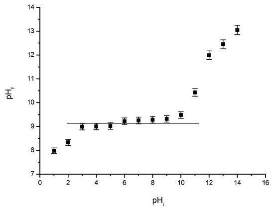
Figure 4.
pHpZc for MgFe2O4 material treated at 260 °C.
In our case the pHpZc is 9.2. This is considered to be the ideal working pH. pZc value represents a clear indication of whether the adsorbent material surface is positively or negatively charge, and depends on the pH value [67].
3.2. Adsorption Studies
3.2.1. pH Effect
The pH effect of the In (III) adsorption is shown in Figure 5.
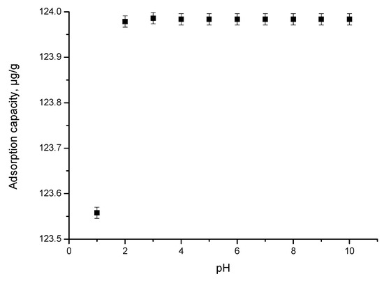
Figure 5.
pH effect.
It is observed that at pH < 2, the adsorption capacity increases with the pH increase, reaching a maximum value of 124 µg In (III)/g MgFe2O4 at pH 2. By any further increase in the pH value, one can observe that the adsorption capacity remains constant. At a pH value lower than 2, according to the literature data, specific species of In (III) coexisting in solution can be: [68,69].
3.2.2. Contact Time and Temperature Effect
The effect of contact time (between 15–120 min) at four different temperatures (298, 308, 318 and 328 K) was studied (obtained data are depicted in Figure 6).
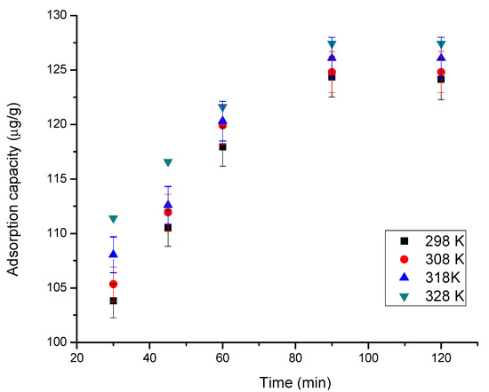
Figure 6.
Contact time and temperature effect.
The results obtained indicate that by increasing the contact time, MgFe2O4 adsorption capacity increases. Moreover, it can be observed that the constant adsorption capacity is reached (~125 µg In (III)/g) after 90 min [70]. With increasing temperature, the adsorption capacity increases, but insignificantly, which is why subsequent studies are performed only at 298 K.
3.2.3. Kinetic Studies
Kinetics of In (III) adsorption on MgFe2O4 material was also evaluated. For that, obtained experimental data were modelled using the equations of the pseudo-first-order and pseudo-second-order kinetic models (Figure 7a,b). To distinguish whether film diffusion or intraparticle diffusion it is the speed determinant step, obtained experimental data were modelled according to the Weber and Morris model, studying intraparticle diffusion (Figure 7c).
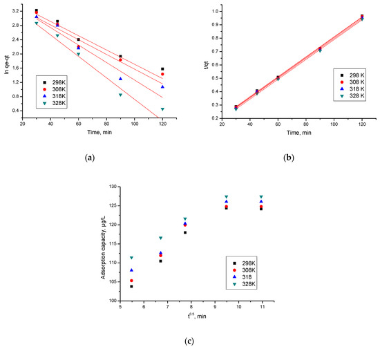
Figure 7.
Kinetic studies. (a) Pseudo-first order; (b) pseudo-second order; (c) intraparticle diffusion.
Based on the results obtained from modelling, were evaluated the values of the speed constants, as well as the values obtained for the diffusion coefficient and C parameters, data presented in Table 3. Withal were calculated the values of the regression coefficient, R2 (depicted in same table).
Table 3.
Kinetic parameters for the adsorption of In (III) onto MgFe2O4.
From the data depicted in Table 3, it can be seen that obtained experimental data are modelled well by the pseudo-second-order kinetic model, proved by the regression coefficient value closer to one, R2~1 (0.9991–0.9996). When obtained experimental data were modelled according to the pseudo-first-order kinetic model one, R2 is between 0.8930 and 0.9114. Moreover, the value of qe,calc calculated based on the pseudo-second-order isotherm it is close to the experimental one (qe, exp). Values of the calculated parameters (k2, qe,calc) are influenced by the temperature value, but not significantly, so it is not necessary to work at temperatures higher than 298 K.
At the same time, it is observed that the adsorption mechanism of In (III) is taking place in several stages, because the line obtained by the graphical representation of the dependence of qt = f(t1/2) at different temperatures, are not passing through the origin (C = 0). Thus, we can say that both intraparticle diffusion and film diffusion influence the kinetics of adsorption. From the data presented in Table 4 it is observed that with increasing temperature the Kdiff value also increases. It is also observed that, specific to stage 1, the diffusion constants are higher than the diffusion constants specific to stage 2, which allows us to state that the determinant of velocity is stage 1 and that in stage 2 the process is slower [71].
Table 4.
Parameters of isotherm model for adsorption In (III) onto MgFe2O4.
3.2.4. Activation Energy
The value of the activation energy, Ea, offers information about the nature of the adsorption process, whether it is a physical or chemical one. This is calculated based on graphical representation of lnK2 vs. 1/T, based on Arrhenius’ equation (Figure 8). In the case of the studied process (In (III) adsorption on the MgFe2O4 material), the activation energy Ea was calculated, using the rate constant from the pseudo-second-order kinetic model k2.
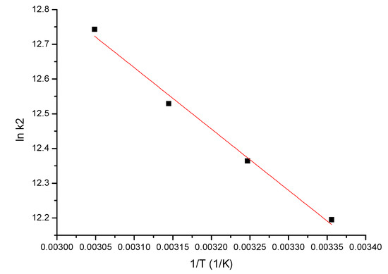
Figure 8.
lnk2 vs. 1/T.
Based on linear dependence depicted in Figure 8, it was calculated the activation energy value (7.46 kJ/mol), which was below 40 kJ/mol, shows us that the studied adsorption process is a physical one [72].
3.2.5. Equilibrium Studies
The adsorption mechanism was established by modelling experimental data with three different isotherms: Langmuir, Freundlich and Sips (obtained data being presented in Figure 9). Isotherms are applied to model obtained experimental data to determine the maximum adsorption capacity of the material. The Freundlich isotherm model assumes that the surface area of the material with adsorbent properties is heterogeneous, so it can be considered that the heat distribution required for the adsorption process on the surface of the adsorbent material is uneven and multilayer adsorption can occur due to unlimited active centres. The Sips isotherm is derived from the Langmuir and Freundlich isotherms. In the case of low adsorbate concentrations, it is reduced to the Freundlich isotherm and, if the adsorbate concentrations are high, it has the characteristics of the Langmuir isotherm. Therefore, this isotherm can be used to calculate the adsorption capacity.
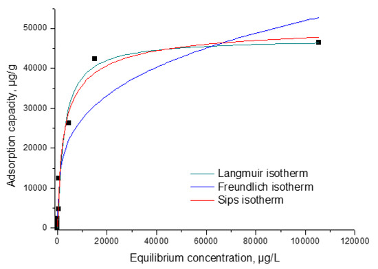
Figure 9.
Equilibrium studies.
From the data presented in Figure 9 were evaluated the specific parameters associated with each isotherm used for modelling the experimental, parameters depicted in Table 4.
The relationship between the equilibrium concentration (Ce) of In (III) and the adsorption capacity demonstrates that as the equilibrium concentration increases, so does the adsorption capacity until equilibrium is reached, establishing the maximum adsorption capacity obtained experimentally, qe,exp (~46.4 mg In (III)/g). It was found, according to the data in Table 5, that the model that best describes the adsorption process is the Sips one, because the regression coefficient, R2, is closest to 1 (R2 = 0.9877), and the theoretical adsorption capacity ~47.5 mg In (III)/g is near the experimental one. Taking in account the data presented in the literature, a comparison of the adsorption capacity obtained for the new prepared material for the recovery of In (III) with adsorption capacity obtained for other materials is presented in Table 5. Based on presented data it was found that the material MgFe2O4 present highest adsorption capacity.
Table 5.
Comparison of adsorption performance with other material for In (III) adsorption.
3.2.6. Thermodynamic Studies
In order to evaluate the value of Gibbs free energy were performed thermodynamic studies in the temperature range 298–328K, by using the Gibbs–Helmholtz equation. Based on the van’t Hoff equation and from the equation of the line obtained from the graphical representation of ln Kd = f(1/T), according to Figure 10, one can calculate the standard variation of the entropy ΔS° and the standard variation of the enthalpy ΔH°.
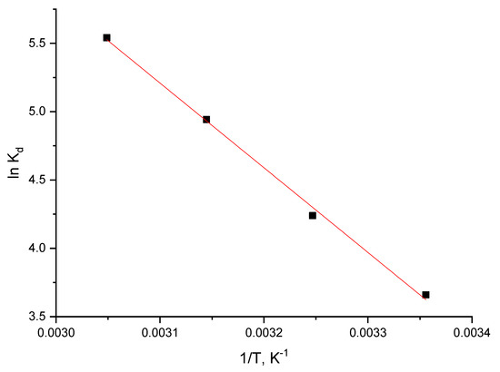
Figure 10.
Thermodynamic studies.
Table 6 shows the thermodynamic parameters resulting from the three temperatures.
Table 6.
Thermodynamic parameters for adsorption of In (III) onto MgFe2O4.
From the resulting data, it is observed that ΔH° has a positive value, meaning that the studied adsorption is endothermic. It is also observed that ΔG° has negative values, increasing in absolute value with temperature increase, indicating that the adsorption process is spontaneous and influenced by temperature. The value of ΔS° is positive which indicates that the adsorption process is favoured, flowing at the interface of the material MgFe2O4/solution with In (III).
An important aspect is that it is represented by the ability to reuse the new adsorbent material. After indium adsorption, the exhausted material was treated with 15% HCl in order to regenerate it. In this way, spinel type adsorbent material was reused 11 times.
4. Conclusions
Obtained experimental data prove that the new prepared adsorbent material (MgFe2O4) can be used with good results for the recovery by adsorption of indium from aqueous solutions. The MgFe2O4 composite was synthesized by the sol-gel method and further characterized by thermogravimetric analysis, Fourier transform infrared spectroscopy and X-ray analysis. The purpose of these analyses was to highlight the formation by heat treatment of magnesium ferrite, MgFe2O4, predominantly and as a secondary phase magnetite. Based on experimental data obtained after performing these analyses we can conclude that the new prepared adsorbent material is preponderantly represented by magnesium ferrite. Further, MgFe2O4 was used in the adsorption experiment in order to recover In ions from aqueous solutions. As a result of the adsorption experiment, we established the working conditions needed to obtain the best adsorption capacity of the material used for In (III) recovery from aqueous solutions. In this context, optimum conditions are: pH > 2, contact time 90 min, temperature 298 K, initial concentration 200 mg L−1. By conducting the adsorption process in optimal conditions we obtained a maximum adsorption capacity of 46.4 mg of In (III) per each gram of adsorbent material. The mechanism of the adsorption process has been highlighted by kinetic, thermodynamic and equilibrium studies. Taking into account the obtained experimental data we can conclude that the studied adsorption is homogeneous, spontaneous, endothermic and temperature-dependent. Based on the Weber and Morris model we can conclude that the In (III) ions takes place at the MgFe2O4/In (III) solution–material interface.
Author Contributions
Investigation, L.C., M.C., P.I., C.I. and N.S.N.; Methodology, P.N.; Supervision, A.N. and P.N.; Validation, N.D.; Writing—original draft, A.N.; Writing—review & editing, N.D. All authors have read and agreed to the published version of the manuscript.
Funding
This work was supported by a grant of the Romanian Ministry of Research, Innovation and Digitalization, project number PFE 26/30.12.2021, PERFORM-CDI@UPT100—The increasing in the performance of the Polytechnic University of Timișoara by strengthening the research, development and technological transfer capacity in the field of “Energy, Environment and Climate Change” at the beginning of the second century of its existence, within Program 1—Development of the national system of Research and Development, Subprogram 1.2—Institutional Performance—Institutional Development Projects—Excellence Funding Projects in RDI, PNCDI III.
Institutional Review Board Statement
Not applicable.
Conflicts of Interest
The authors declare no conflict of interest.
References
- Adhikari, B.B.; Gurung, M.; Kawakita, H.; Ohto, K. Solid phase extraction, preconcentration and separation of indium with methylene crosslinked calix[4]- and calix[6]arene carboxylic acid resins. Chem. Eng. Sci. 2012, 78, 144–154. [Google Scholar] [CrossRef]
- Li, M.; Feng, C.; Li, M.; Zeng, Q.; Gan, Q. Synthesis and application of a surface-grafted In (III) ion-imprinted polymer for selective separation and pre-concentration of indium (III) ion from aqueous solution. Hydrometallurgy 2015, 154, 63–71. [Google Scholar] [CrossRef]
- Li, G.; Zhang, B.; Ma, Z.; Wang, Z. Facile synthesis of hydroxyl- and amine-riched porous polymer for indium recovery in water. Microporous Mesoporous Mater. 2021, 323, 111162. [Google Scholar] [CrossRef]
- Duan, H.; Wang, J.; Liu, L.; Huang, Q.; Li, J. Rethinking China’s strategic mineral policy on indium: Implication for the flat screens and photovoltaic industries. Prog. Photovolt. Res. Appl. 2016, 24, 83–93. [Google Scholar] [CrossRef]
- Díez, E.; Gómez, J.M.; Rodríguez, A.; Bernabé, I.; Sáez, P.; Galán, J. A new mesoporous activated carbon as potential adsorbent for effective indium removal from aqueous solutions. Microporous Mesoporous Mater. 2020, 295, 109984. [Google Scholar] [CrossRef]
- Zimmermann, Y.-S.; Niewersch, C.; Lenz, M.; Kül, Z.Z.; Corvini, P.F.-X.; Schäffer, A.; Wintgens, T. Recycling of Indium From CIGS Photovoltaic Cells: Potential of Combining Acid-Resistant Nanofiltration with Liquid–Liquid Extraction. Environ. Sci. Technol. 2014, 48, 13412–13418. [Google Scholar] [CrossRef]
- Assefi, M.; Maroufi, S.; Nekouei, R.K.; Sahajwalla, V. Selective recovery of indium from scrap LCD panels using macroporous resins. J. Clean. Prod. 2018, 180, 814–822. [Google Scholar] [CrossRef]
- Alfantazi, A.; Moskalyk, R. Processing of indium: A review. Miner. Eng. 2003, 16, 687–694. [Google Scholar] [CrossRef]
- Lee, S.-K.; Lee, U.-H. Adsorption and desorption property of iminodiacetate resin (Lewatit® TP207) for indium recovery. J. Ind. Eng. Chem. 2016, 40, 23–25. [Google Scholar] [CrossRef]
- Li, H.; Liu, J.; Gao, X.; Liu, C.; Guo, L.; Zhang, S.; Liu, X.; Liu, C. Adsorption behavior of indium(III) on modified solvent impregnated resins (MSIRs) containing sec-octylphenoxy acetic acid. Hydrometallurgy 2012, 121–124, 60–67. [Google Scholar] [CrossRef]
- Li, J.; Gao, S.; Duan, H.; Liu, L. Recovery of valuable materials from waste liquid crystal display panel. Waste Manag. 2009, 29, 2033–2039. [Google Scholar] [CrossRef]
- Rocchetti, L.; Amato, A.; Fonti, V.; Ubaldini, S.; de Michelis, I.; Kopacek, B.; Vegliò, F.; Beolchini, F. Cross-current leaching of indium from end-of-life LCD panels. Waste Manag. 2015, 42, 180–187. [Google Scholar] [CrossRef] [PubMed]
- Bakry, A.M.; Alamier, W.M.; Salama, R.S.; El-Shall, M.S.; Awad, F.S. Remediation of water containing phosphate using ceria nanoparticles decorated partially reduced graphene oxide (CeO2-PRGO) composite. Surfaces Interfaces 2022, 31, 102006. [Google Scholar] [CrossRef]
- Calagui, M.J.C.; Senoro, D.B.; Kan, C.-C.; Salvacion, J.W.; Futalan, C.M.; Wan, M.-W. Adsorption of indium(III) ions from aqueous solution using chitosan-coated bentonite beads. J. Hazard. Mater. 2014, 277, 120–126. [Google Scholar] [CrossRef] [PubMed]
- Limin, Y.; Wenquan, J.; Zhongzhen, F. Purification of indium electrolyte by coprecipitation. Mater. Rev. 2011, 25, 72–74. [Google Scholar]
- Swain, B.; Mishra, C.; Hong, H.S.; Cho, S.-S.; Lee, S.k. Commercial process for the recovery of metals from ITO etching industry wastewater by liquid–liquid extraction: Simulation, analysis of mechanism, and mathematical model to predict optimum operational conditions. Green Chem. 2015, 17, 3979–3991. [Google Scholar] [CrossRef]
- Gupta, B.; Mudhar, N.; Singh, I. Separations and recovery of indium and gallium using bis(2,4,4-trimethylpentyl)phosphinic acid (Cyanex 272). Sep. Purif. Technol. 2007, 57, 294–303. [Google Scholar] [CrossRef]
- Lee, M.; Ahn, J.; Lee, E. Solvent extraction separation of indium and gallium from sulphate solutions using D2EHPA. Hydrometallurgy 2002, 63, 269–276. [Google Scholar] [CrossRef]
- Trochimczuk, A.W.; Czerwińska, S. In(III) and Ga(III) sorption by polymeric resins with substituted phenylphosphinic acid ligands. React. Funct. Polym. 2005, 63, 215–220. [Google Scholar] [CrossRef]
- Zhang, X.; Yin, G.; Hu, Z. Extraction and separation of gallium, indium and thallium with several carboxylic acids from chloride media. Talanta 2003, 59, 905–912. [Google Scholar] [CrossRef]
- Yang, J.; Retegan, T.; Ekberg, C. Indium recovery from discarded LCD panel glass by solvent extraction. Hydrometallurgy 2013, 137, 68–77. [Google Scholar] [CrossRef]
- Wu, M.; Sun, D.D.; Tay, J.H. Effect of operating variables on rejection of indium using nanofiltration membranes. J. Membr. Sci. 2004, 240, 105–111. [Google Scholar] [CrossRef]
- He, Y.; Ma, E.; Xu, Z. Recycling indium from waste liquid crystal display panel by vacuum carbon-reduction. J. Hazard. Mater. 2014, 268, 185–190. [Google Scholar] [CrossRef] [PubMed]
- Medvecky, L.; Briančin, J. Possibilities of simultaneous determination of indium and gallium in binary InGa alloys by anodic stripping voltammetry in acetate buffer. Chem. Pap. 2004, 58, 93–100. [Google Scholar]
- Ferreira, E.D.M.M.; Morelli, T.; Moreira, I.M.N.S.; De Carvalho, M.S. Studies on indium sorption from iodide medium by polyurethane foam. J. Braz. Chem. Soc. 2004, 15, 563–569. [Google Scholar] [CrossRef]
- Liu, J.S.; He, Z.G.; Cai, J.; Cai, C.G.; Zhou, B.X.; Cai, W.M. Separation of indium (III), gallium (III), and zinc (II) with Levextrel resin containing di(2-ethylhexyl) phosphoric acid (CL-P204): Part I. Selection of separation conditions. Rare Met. 2003, 22, 235–240. [Google Scholar]
- Liu, J.; Chen, H.; Chen, X.; Guo, Z.; Hu, Y.; Liu, C.; Sun, Y. Extraction and separation of In(III), Ga(III) and Zn(II) from sulfate solution using extraction resin. Hydrometallurgy 2006, 82, 137–143. [Google Scholar] [CrossRef]
- Yuan, Y.; Liu, J.; Zhou, B.; Yao, S.; Li, H.; Xu, W. Synthesis of coated solvent impregnated resin for the adsorption of indium (III). Hydrometallurgy 2010, 101, 148–155. [Google Scholar] [CrossRef]
- Song, Q.; Liu, Y.; Zhang, L.; Xu, Z. Facile indium recovery from waste liquid crystal displays: Chloride-facilitated indium electroreduction and stepwise Cu/MoO2 and indium electrodeposition. J. Hazard. Mater. 2021, 415, 125599. [Google Scholar] [CrossRef]
- Armstrong, R.D.; Todd, M.; Atkinson, J.W.; Scott, K. Selective electrodeposition of metals from simulated waste solutions. J. Appl. Electrochem. 1996, 26, 379–384. [Google Scholar] [CrossRef]
- Ibrahim, A.A.; Salama, R.S.; El-Hakam, S.A.; Khder, A.S.; Ahmed, A.I. Synthesis of 12-tungestophosphoric acid supported on Zr/MCM-41 composite with excellent heterogeneous catalyst and promising adsorbent of methylene blue. Colloids Surfaces A Physicochem. Eng. Asp. 2021, 631, 127753. [Google Scholar] [CrossRef]
- Salama, R.S.; El-Sayed, E.-S.M.; El-Bahy, S.M.; Awad, F.S. Silver nanoparticles supported on UiO-66 (Zr): As an efficient and recyclable heterogeneous catalyst and efficient adsorbent for removal of Indigo Carmine. Colloids Surfaces A Physicochem. Eng. Asp. 2021, 626, 127089. [Google Scholar] [CrossRef]
- Atkins, P.; de Paula, J. Atkins’ Physical Chemistry; Oxford University Press: Oxford, UK, 2005; p. 1008. [Google Scholar]
- de Freitas, F.; Battirola, L.D.; de Andrade, R.L.T. Adsorption of Cu2+ and Pb2+ Ions by Pontederia rotundifolia (L.f.) (Pontederiaceae) and Salvinia biloba Raddi (Salviniaceae) Biomass. Water Air Soil Pollut. 2018, 229, 349. [Google Scholar] [CrossRef]
- Freundlich, H.M.F. Over the adsorption in solution. J. Phys. Chem. 1906, 57, 385–470. [Google Scholar]
- Tuzen, M.; Soylak, M. Chromium speciation in environmental samples by solid phase extraction on Chromosorb 108. J. Hazard. Mater. 2006, 129, 266–273. [Google Scholar] [CrossRef]
- Fortes, M.; Martins, A.; Benedetto, J. Indium adsorption onto ion exchange polymeric resins. Miner. Eng. 2003, 16, 659–663. [Google Scholar] [CrossRef]
- Tokuyama, H.; Iwama, T. Solid-phase extraction of indium(III) ions onto thermosensitive poly(N-isopropylacrylamide). Sep. Purif. Technol. 2009, 68, 417–421. [Google Scholar] [CrossRef]
- Wang, S.; Sun, H.; Ang, H.M.; Tadé, M.O. Adsorptive remediation of environmental pollutants using novel graphene-based nanomaterials. Chem. Eng. J. 2013, 226, 336–347. [Google Scholar] [CrossRef]
- Tuzen, M.; Soylak, M. A solid phase extraction procedure for Indium prior to its graphite furnace atomic absorption spectrometric determination. J. Hazard. Mater. 2006, 129, 179–185. [Google Scholar] [CrossRef]
- Hoogerstraete, T.V.; Onghena, B.; Binnemans, K. Homogeneous Liquid–Liquid Extraction of Metal Ions with a Functionalized Ionic Liquid. J. Phys. Chem. Lett. 2013, 4, 1659–1663. [Google Scholar] [CrossRef]
- Liu, H.-M.; Wu, C.-C.; Lin, Y.-H.; Chiang, C.-K. Recovery of indium from etching wastewater using supercritical carbon dioxide extraction. J. Hazard. Mater. 2009, 172, 744–748. [Google Scholar] [CrossRef] [PubMed]
- Bossche, A.V.D.; Vereycken, W.; Hoogerstraete, T.V.; Dehaen, W.; Binnemans, K. Recovery of Gallium, Indium, and Arsenic from Semiconductors Using Tribromide Ionic Liquids. ACS Sustain. Chem. Eng. 2019, 7, 14451–14459. [Google Scholar] [CrossRef]
- Ozkantar, N.; Yilmaz, E.; Soylak, M.; Tuzen, M. Solid-phase extraction of iridium from soil and water samples by using activated carbon cloth prior to its spectrophotometric determination. Environ. Monit. Assess. 2015, 187, 501. [Google Scholar] [CrossRef]
- Memon, F.N.; Ayyilidiz, H.F.; Kara, H.; Memon, S.; Kenar, A.; Leghari, M.K.; Topkafa, M.; Sherazi, S.T.H.; Memon, N.A.; Durmaz, F.; et al. Application of central composite design for the optimization of on-line solid phase extraction of Cu2+ by calix[4]arene bonded silica resin. Chemom. Intell. Lab. Syst. 2015, 146, 158–168. [Google Scholar] [CrossRef]
- Alguacil, F.; Lopez, F.; Rodriguez, O.; Martinez-Ramirez, S.; Garcia-Diaz, I. Sorption of indium (III) onto carbon nanotubes. Ecotoxicol. Environ. Saf. 2016, 130, 81–86. [Google Scholar] [CrossRef] [PubMed]
- Naaz, F.; Dubey, H.K.; Kumari, C.; Lahiri, P. Structural and magnetic properties of MgFe2O4 nanopowder synthesized via co-precipitation route. SN Appl. Sci. 2020, 2, 808. [Google Scholar] [CrossRef]
- Bloesser, A.; Kurz, H.; Timm, J.; Wittkamp, F.; Simon, C.; Hayama, S.; Weber, B.; Apfel, U.-P.; Marschall, R. Tailoring the Size, Inversion Parameter, and Absorption of Phase-Pure Magnetic MgFe2O4 Nanoparticles for Photocatalytic Degradations. ACS Appl. Nano Mater. 2020, 3, 11587–11599. [Google Scholar] [CrossRef]
- Hammache, Z.; Soukeur, A.; Omeiri, S.; Bellal, B.; Trari, M. Physical and photo-electrochemical properties of MgFe2O4 prepared by sol gel route: Application to the photodegradation of methylene blue. J. Mater. Sci. Mater. Electron. 2019, 30, 5375–5382. [Google Scholar] [CrossRef]
- Becker, A.; Kirchberg, K.; Marschall, R. Magnesium Ferrite (MgFe2O4) Nanoparticles for Photocatalytic Antibiotics Degradation. Z. Für Phys. Chem. 2020, 234, 645–654. [Google Scholar] [CrossRef]
- Sun, J.R.; Wang, Z.G.; Wang, Y.Y.; Wei, K.F.; Li, F.S. Structure and Magnetic Properties of MgFe2O4 Nanoparticles Prepared by the Low-Temperature Solid-State Reaction Method. Mater. Sci. Forum 2011, 686, 316–318. [Google Scholar] [CrossRef]
- Reddy, S.; Swamy, B.E.K.; Chandra, U.; Mahathesha, K.R.; Sathisha, T.V.; Jayadevappa, H. Synthesis of MgFe2O4 nanoparticles and MgFe2O4 nanoparticles/CPE for electrochemical investigation of dopamine. Anal. Methods 2011, 3, 2792–2796. [Google Scholar] [CrossRef]
- Lagergren, S. About the theory of so-called adsorption of soluble substabces. Kungl. Sven. Vetensk. Handl. 1898, 24, 1–39. [Google Scholar]
- Ho, Y.-S. Review of second-order models for adsorption systems. J. Hazard. Mater. 2006, 136, 681–689. [Google Scholar] [CrossRef]
- Ho, Y.S.; McKay, G. A Comparison of Chemisorption Kinetic Models Applied to Pollutant Removal on Various Sorbents. Process Saf. Environ. Prot. 1998, 76, 332–340. [Google Scholar] [CrossRef]
- Weber, W.J.; Morris, J.C. Kinetics of Adsorption on Carbon from Solution. J. Sanit. Eng. Div. 1963, 89, 31–59. [Google Scholar] [CrossRef]
- Weber, W.J.; Morris, J.C. Equilibria and Capacities for Adsorption on Carbon. J. Sanit. Eng. Div. 1964, 90, 79–108. [Google Scholar] [CrossRef]
- Langmuir, I. The adsorption of gases on plane surfaces of glass, mica and platinum. J. Am. Chem. Soc. 1918, 40, 1361–1403. [Google Scholar] [CrossRef]
- Sips, R. On the Structure of a Catalyst Surface. J. Chem. Phys. 1948, 16, 490–495. [Google Scholar] [CrossRef]
- Maensiri, S.; Sangmanee, M.; Wiengmoon, A. Magnesium Ferrite (MgFe2O4) Nanostructures Fabricated by Electrospinning. Nanoscale Res. Lett. 2008, 4, 221–228. [Google Scholar] [CrossRef]
- Upadhyay, S.; Sreenivas, K. Comparative Studies of MgFe2O4 Nanoparticles Synthesized using Different Precursors by Sol Gel Auto Combustion Method. J. At. Mol. Condens. Nano Phys. 2015, 2, 101–108. [Google Scholar] [CrossRef]
- Ilhan, S.; Izotova, S.G.; Komlev, A.A. Synthesis and characterization of MgFe2O4 nanoparticles prepared by hydrothermal decomposition of co-precipitated magnesium and iron hydroxides. Ceram. Int. 2015, 41, 577–585. [Google Scholar] [CrossRef]
- Nicola, R.; Costişor, O.; Ciopec, M.; Negrea, A.; Lazău, R.; Ianăşi, C.; Picioruş, E.-M.; Len, A.; Almásy, L.; Szerb, E.I.; et al. Silica-Coated Magnetic Nanocomposites for Pb2+ Removal from Aqueous Solution. Appl. Sci. 2020, 10, 2726. [Google Scholar] [CrossRef]
- Sepahvand, R. Synthesis and Characterization of Carbon Nanotubes Decorated with Magnesium Ferrite (MgFe2O4) Nanoparticles by Citrate-Gel Method. J. Sci. Islam. Repub. Iran 2011, 22, 177–182. [Google Scholar] [CrossRef]
- Pradeep, A.; Priyadharsini, P.; Chandrasekaran, G. Sol–gel route of synthesis of nanoparticles of MgFe2O4 and XRD, FTIR and VSM study. J. Magn. Magn. Mater. 2008, 320, 2774–2779. [Google Scholar] [CrossRef]
- Robles, J. The Engineering of Pt/Carbon Catalyst Preparation-For Application on Proton Exchange Fuel Cell Membrane; Univrsity of Illinois at Chicago: Chicago, IL, USA, 2004. [Google Scholar]
- Vidal, C.; do Nascimento, R.; Raulino, G.; Clecius, A.; Melo, D. Adsorção: Aspectos Teóricos e Aplicações Ambientais; Imprensa Universitária: Fortaleza, Brazil, 2014. [Google Scholar]
- Werner, A.; Rieger, A.; Mosch, M.; Haseneder, R.; Repke, J.-U. Nanofiltration of indium and germanium ions in aqueous solutions: Influence of pH and charge on retention and membrane flux. Sep. Purif. Technol. 2017, 194, 319–328. [Google Scholar] [CrossRef]
- Baes, C.F.; Mesmer, R.S. The Hydrolysis of Cations. Ber. Der Bunsenges. Für Phys. Chem. 1977, 81, 245–246. [Google Scholar]
- Akama, Y.; Suzuki, S.; Monobe, Y. Study on the adsorption and selective separation of indium from zinc with chelating cellulose. Cellul. Chem. Technol. 2016, 50, 147–152. [Google Scholar]
- Zhang, S.; Ning, S.; Liu, H.; Zhou, J.; Wang, S.; Zhang, W.; Wang, X.; Wei, Y. Highly-efficient separation and recovery of ruthenium from electroplating wastewater by a mesoporous silica-polymer based adsorbent. Microporous Mesoporous Mater. 2020, 303, 110293. [Google Scholar] [CrossRef]
- Zhang, Y.; Yu, F.; Cheng, W.; Wang, J.; Ma, J. Adsorption Equilibrium and Kinetics of the Removal of Ammoniacal Nitrogen by Zeolite X/Activated Carbon Composite Synthesized from Elutrilithe. J. Chem. 2017, 2017, 1–9. [Google Scholar] [CrossRef]
- Marinho, R.S.; da Silva, C.N.; Afonso, J.C.; da Cunha, J.W.S.D. Recovery of platinum, tin and indium from spent catalysts in chloride medium using strong basic anion exchange resins. J. Hazard. Mater. 2011, 192, 1155–1160. [Google Scholar] [CrossRef]
- Kwak, N.-S.; Baek, Y.; Hwang, T.S. The synthesis of poly(vinylphosphonic acid-co-methacrylic acid) microbeads by suspension polymerization and the characterization of their indium adsorption properties. J. Hazard. Mater. 2012, 203–204, 213–220. [Google Scholar] [CrossRef] [PubMed]
Publisher’s Note: MDPI stays neutral with regard to jurisdictional claims in published maps and institutional affiliations. |
© 2022 by the authors. Licensee MDPI, Basel, Switzerland. This article is an open access article distributed under the terms and conditions of the Creative Commons Attribution (CC BY) license (https://creativecommons.org/licenses/by/4.0/).