
Polydispersity vs. Monodispersity. How the Properties of Ni-Ag Core-Shell Nanoparticles Affect the Conductivity of Ink Coatings


Abstract
1. Introduction
2. Materials and Methods
2.1. Materials
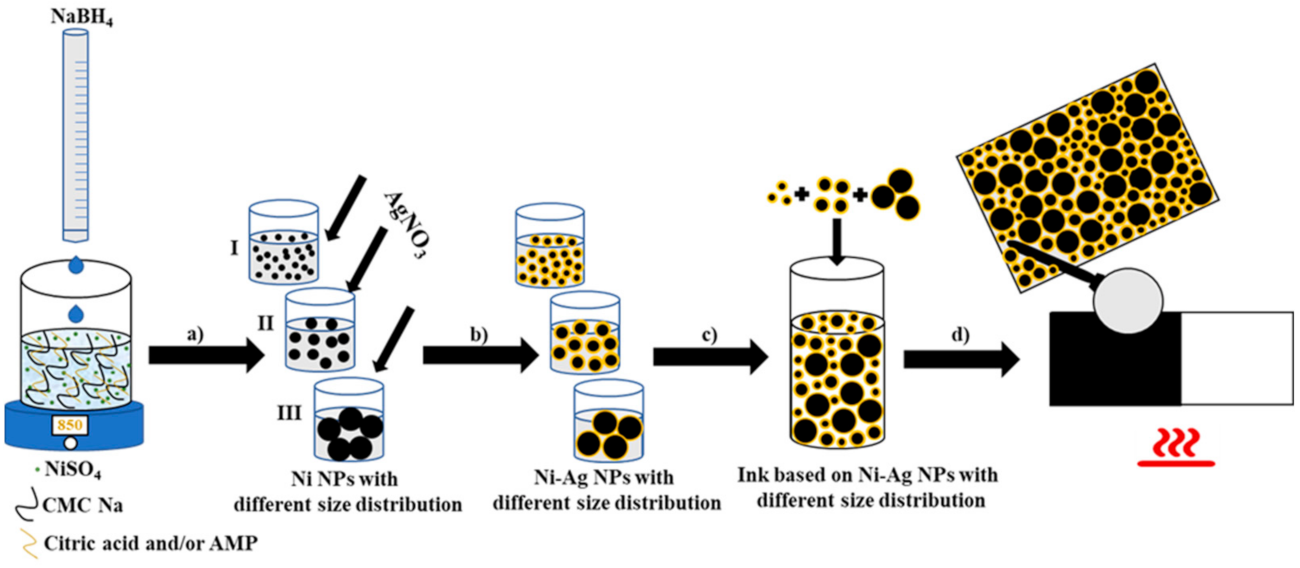
2.2. Synthesis of Ni-Ag NPs
2.3. Ink Composition and Conductive Coatings Fabrication
2.4. Characterization
3. Results and Discussion
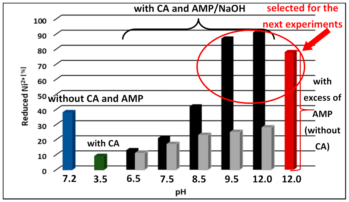
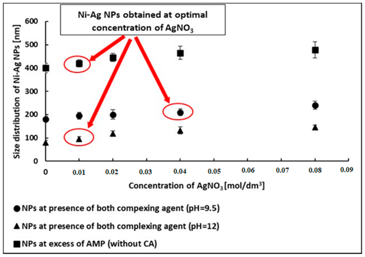
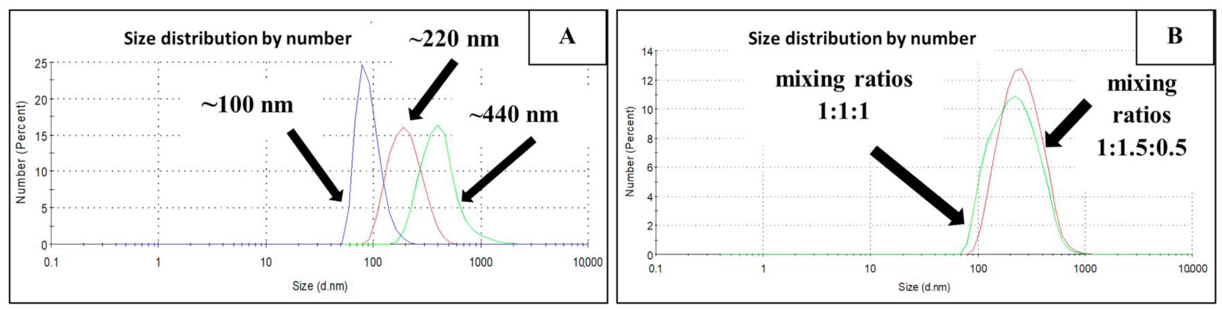
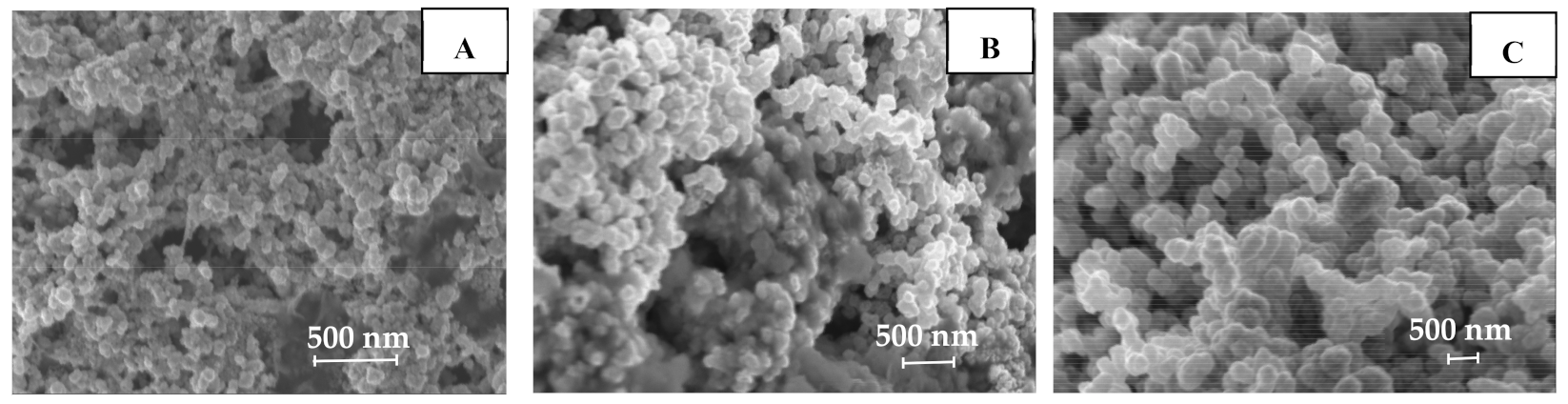
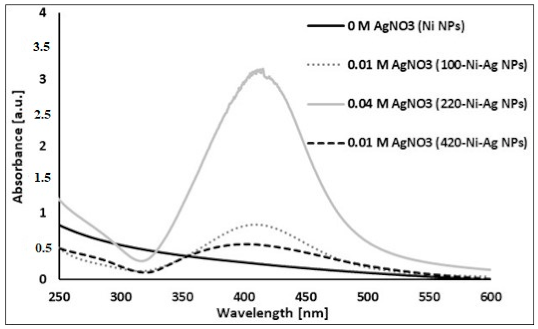
3.1. Preparation of Polydisperse Ni-Ag NPs Dispersion
3.2. Ink Composition and Fabrication of Conductive Coatings
4. Conclusions
Supplementary Materials
Author Contributions
Funding
Institutional Review Board Statement
Informed Consent Statement
Data Availability Statement
Acknowledgments
Conflicts of Interest
References
- Gaikwad, A.; Steingart, D.A.; Ng, T.N.; Schwartz, D.E.; Whiting, G.L. A flexible high potential printed battery for powering printed electronics. Appl. Phys. Lett. 2013, 102, 233302. [Google Scholar] [CrossRef]
- Salmerón, J.F.; Molina-Lopez, F.; Briand, D.; Ruan, J.J.; Rivadeneyra, A.; Carvaja, M.A.; Capitán-Vallrey, L.F.; Derooij, N.F.; Palma, A.J. Properties and printability of inkjet and screen-printed silver patterns for RFID antennas. J. Electron. Mater. 2014, 43, 604–617. [Google Scholar] [CrossRef]
- Layani, M.; Darmawan, P.; Foo, W.; Liu, L.; Kamyshny, A.; Mandler, D.; Magdassi, S.; Lee, P.S. Nanostructures electrochromic films by inkjet printing on large area and flexible transparent silver electrodes. Nanoscale 2014, 6, 4572–4576. [Google Scholar] [CrossRef] [PubMed]
- Shanyong, C.; Guan, Y.; Li, Y.; Yan, X.; Ni, H.; Li, L. A water-based silver nanowire ink for large-scale flexible transparent conductive films and touch screens. J. Mater. Chem. 2017, 5, 2404–2414. [Google Scholar]
- Kamyshny, A.; Magdassi, S. (Eds.) Metallic nanoinks for inkjet printing of conductive 2D and 3D structures. In Nanomaterials for 2D and 3D Printing; Wiley: Weinheim, Germany, 2017; Chapter 7; pp. 119–160. [Google Scholar]
- Kamyshny, A.; Magdassi, S. Conductive nanomaterials for 2D and 3D printed flexible electronics. Chem. Soc. Rev. 2019, 48, 1712–1740. [Google Scholar] [CrossRef]
- Kamyshny, A.; Magdassi, S. Conductive nanomaterials for printed electronics. Small 2014, 17, 3515–3535. [Google Scholar] [CrossRef]
- Naghdi, S.; Rhee, K.Y.; Hui, D.; Park, S.J. A review of conductive metal nanomaterials as conductive, transparent, and flexible coatings, thin films, and conductive fillers: Different deposition methods and applications. Coatings 2018, 8, 278. [Google Scholar] [CrossRef]
- Pajor-Świerzy, A.; Pawłowski, R.; Warszyński, P.; Szczepanowicz, K. The conductive properties of ink coating based on Ni–Ag core–shell nanoparticles with the bimodal size distribution. J. Mater. Sci. Mater. Electron. 2020, 31, 12991–12999. [Google Scholar] [CrossRef]
- Wünscher, S.; Abbel, R.; Perelaer, J.; Schubert, U.S. Progress of alternative sintering approaches of inkjet-printed metal inks and their application for manufacturing of flexible electronic devices. J. Mater. Chem. 2014, 2, 10232–10261. [Google Scholar] [CrossRef]
- Magdassi, S.; Grouchko, M.; Kamyshny, A. Copper nanoparticles for printed electronics: Routes towards achieving oxidation stability. Materials 2010, 3, 4626–4638. [Google Scholar] [CrossRef] [PubMed]
- Zhang, Z.; Zhang, X.; Xin, Z.; Deng, M.; Wen, Y.; Song, Y. Synthesis of monodisperse silver nanoparticles for ink-jet printed flexible electronics. Nanotechnology 2011, 22, 425601. [Google Scholar] [CrossRef]
- Liu, L.; Wan, X.; Sun, L.; Yang, S.; Dai, Z.; Tian, Q.; Lei, M.; Xiao, X.; Jiang, C.; Wu, W. Anion-mediated synthesis of monodisperse silver nanoparticles useful for screen printing of high conductivity patterns on flexible substrates for printed electronics. Rsc. Adv. 2015, 5, 9783–9791. [Google Scholar] [CrossRef]
- Park, J.; Moon, J. Control of colloidal particle deposit patterns within picoliter droplets ejected by ink-jet printing. Langmuir 2006, 22, 3506–3513. [Google Scholar] [CrossRef]
- Uryupina, O.Y.; Urodkova, E.K.; Zhavoronok, E.S.; Vysotskii, V.V.; Senchikhin, I.N. Synthesis of Monodisperse Silver Nanoparticles in Chitosan Solutions. Colloid J. 2019, 81, 263–267. [Google Scholar] [CrossRef]
- Balantrapu, K.; McMurran, M.; Goia, D.V. Inkjet printable silver dispersions: Effect of bimodal particle-size distribution on film formation and electrical conductivity. J. Mater. Res. 2010, 25, 821–827. [Google Scholar] [CrossRef]
- Wu, Y.; Wang, Z.; Zhao, X.; Tan, M.C. Size and surface effects on chemically-induced joining of Ag conductive inks. CrystEngComm 2018, 20, 6300–6309. [Google Scholar] [CrossRef]
- Pajor-Świerzy, A.; Gaweł, D.; Drzymała, E.; Socha, R.; Parlińska-Wojtan, M.; Szczepanowicz, K.; Warszyński, P. The optimization of methods of synthesis of nickel-silver core-shell nanoparticles for conductive materials. Nanotechnology 2018, 30, 1–8. [Google Scholar] [CrossRef]
- Pajor-Świerzy, A.; Socha, R.; Pawłowski, R.; Warszynski, P.; Szczepanowicz, K. Application of metallic inks based on nickel-silver core-shell nanoparticles for fabrication of conductive films. Nanotechnology 2019, 30, 225301. [Google Scholar] [CrossRef]
- K-hand Coater, Pre-Press Equipment, RK Print Coat Instruments. Available online: https://www.rkprint.com/products/k-hand-coater/ (accessed on 12 October 2020).
- Kamyshny, A.; Steinke, J.; Magdassi, S. Metal-based inkjet inks for printed electronics. Open Appl. Phys. J. 2011, 4, 19–36. [Google Scholar] [CrossRef]
- Pajor-Świerzy, A.; Farraj, Y.; Kamyshny, A.; Magdassi, S. Air stable copper-silver core-shell submicron particles: Synthesis and conductive ink formulation. Colloids Surf. A Phys. Eng. Asp. 2017, 521, 272–280. [Google Scholar] [CrossRef]
- Roy, P.S.; Bhattacharya, S.K. Size-controlled synthesis, characterization and electrocatalytic behaviors of polymer-protected nickel nanoparticles: A comparison with respect to two polymers. RSC Adv. 2014, 4, 13892. [Google Scholar] [CrossRef]
- Yokoyama, S.; Takahashi, H.; Tohji, K. Novel synthesis method of copper nanoparticles by controlling metal complexes in aqueous solution. Meet. Abstr. 2012, 2, 233. [Google Scholar]
- Kamali, M.; Ghorashi, S.A.A.; Asadollahi, M.A. Controllable synthesis of silver nanoparticles using citrate as complexing agent: Characterization of nanopartciles and effect of pH on size and crystallinity. Iran. J. Chem. Chem. Eng. 2012, 31, 21–28. [Google Scholar]
- Venkatesha, N.J.; Ramesh, S. Citric Acid-Assisted Synthesis of Nanoparticle Copper Catalyst Supported on an Oxide System for the Reduction of Furfural to Furfuryl Alcohol in the Vapor Phase. Ind. Eng. Chem. Res. 2018, 57, 1506–1515. [Google Scholar] [CrossRef]
- Sun, Y.; Xia, Y. Gold and silver nanoparticles: A class of chromophores with colors tunable in the range from 400 to 750 nm. Analyst 2003, 128, 686–691. [Google Scholar] [CrossRef] [PubMed]
- Miyakawa, M.; Hiyoshi, N.; Nishioka, M.; Koda, H.; Sato, K.; Miyazawa, A.; Suzuki, T.M. Continuous syntheses of Pd@Pt and Cu@Ag core–shell nanoparticles using microwave-assisted core particle formation coupled with galvanic metal displacement. Nanoscale 2014, 6, 8720. [Google Scholar] [CrossRef]
- Coatings & Thin Films, Kratos Analytical. Available online: https://www.kratos.com/applications/coatings-thin-film (accessed on 10 November 2020).
- Jing, J.J.; Xie, J.; Chen, G.Y.; Li, W.H.; Zhang, M.M. Preparation of nickel silver core–shell nanoparticles by liquid-phase reduction for use in conductive paste. J. Exp. Nanosci. 2015, 10, 1347–1356. [Google Scholar] [CrossRef]
- Park, S.H.; Kim, H.S. Flash light sintering of nickel nanoparticles for printed electronics. Thin Solid Film. 2014, 550, 575–581. [Google Scholar] [CrossRef]


| Synthesis Conditions | Average Size [nm] | Polydispersity Index (PDI) |
|---|---|---|
| AMP + CA at pH 9.5 | 180 ± 15 | 0.152 ± 0.033 |
| AMP + CA at pH 12 | 80 ± 10 | 0.093 ± 0.021 |
| AMP at pH 12 | 400 ± 25 | 0.211 ± 0.029 |
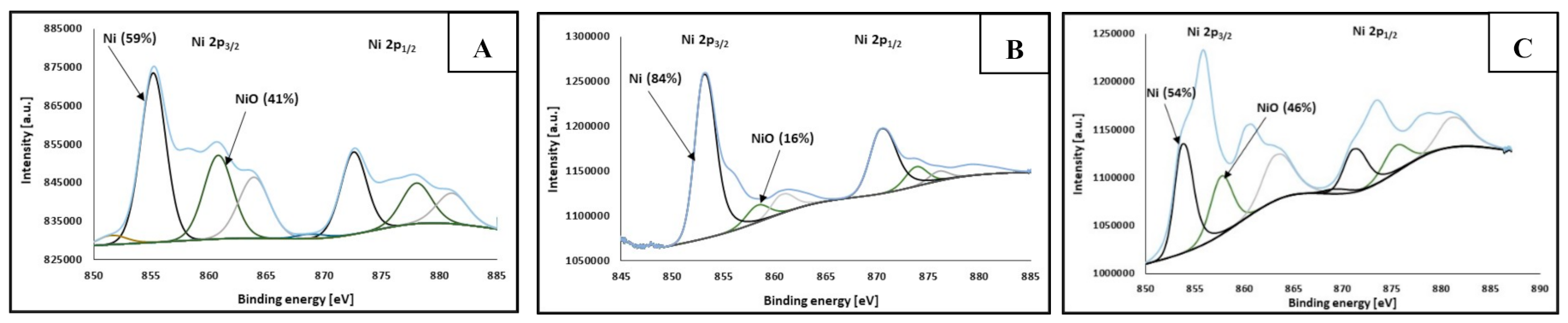
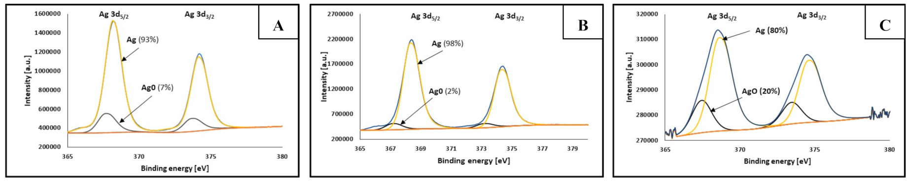
| Average Size [nm] | Atomic Percentage [%] | |||
|---|---|---|---|---|
| Metallic Nickel | Nickel Oxide (NiO) | Metallic Silver | Silver Oxide | |
| 100 | 59 | 41 | 93 | 7 |
| 220 | 84 | 16 | 98 | 2 |
| 420 | 54 | 46 | 80 | 20 |
Publisher’s Note: MDPI stays neutral with regard to jurisdictional claims in published maps and institutional affiliations. |
© 2021 by the authors. Licensee MDPI, Basel, Switzerland. This article is an open access article distributed under the terms and conditions of the Creative Commons Attribution (CC BY) license (https://creativecommons.org/licenses/by/4.0/).
Share and Cite
Pajor-Świerzy, A.; Staśko, D.; Pawłowski, R.; Mordarski, G.; Kamyshny, A.; Szczepanowicz, K. Polydispersity vs. Monodispersity. How the Properties of Ni-Ag Core-Shell Nanoparticles Affect the Conductivity of Ink Coatings. Materials 2021, 14, 2304. https://doi.org/10.3390/ma14092304
Pajor-Świerzy A, Staśko D, Pawłowski R, Mordarski G, Kamyshny A, Szczepanowicz K. Polydispersity vs. Monodispersity. How the Properties of Ni-Ag Core-Shell Nanoparticles Affect the Conductivity of Ink Coatings. Materials. 2021; 14(9):2304. https://doi.org/10.3390/ma14092304
Chicago/Turabian StylePajor-Świerzy, Anna, Dawid Staśko, Radosław Pawłowski, Grzegorz Mordarski, Alexander Kamyshny, and Krzysztof Szczepanowicz. 2021. "Polydispersity vs. Monodispersity. How the Properties of Ni-Ag Core-Shell Nanoparticles Affect the Conductivity of Ink Coatings" Materials 14, no. 9: 2304. https://doi.org/10.3390/ma14092304
APA StylePajor-Świerzy, A., Staśko, D., Pawłowski, R., Mordarski, G., Kamyshny, A., & Szczepanowicz, K. (2021). Polydispersity vs. Monodispersity. How the Properties of Ni-Ag Core-Shell Nanoparticles Affect the Conductivity of Ink Coatings. Materials, 14(9), 2304. https://doi.org/10.3390/ma14092304