
Semi Salix Leaf Textured Gas Mechanical Face Seal with Enhanced Opening Performance


Abstract
:1. Introduction
2. Theoretical Model
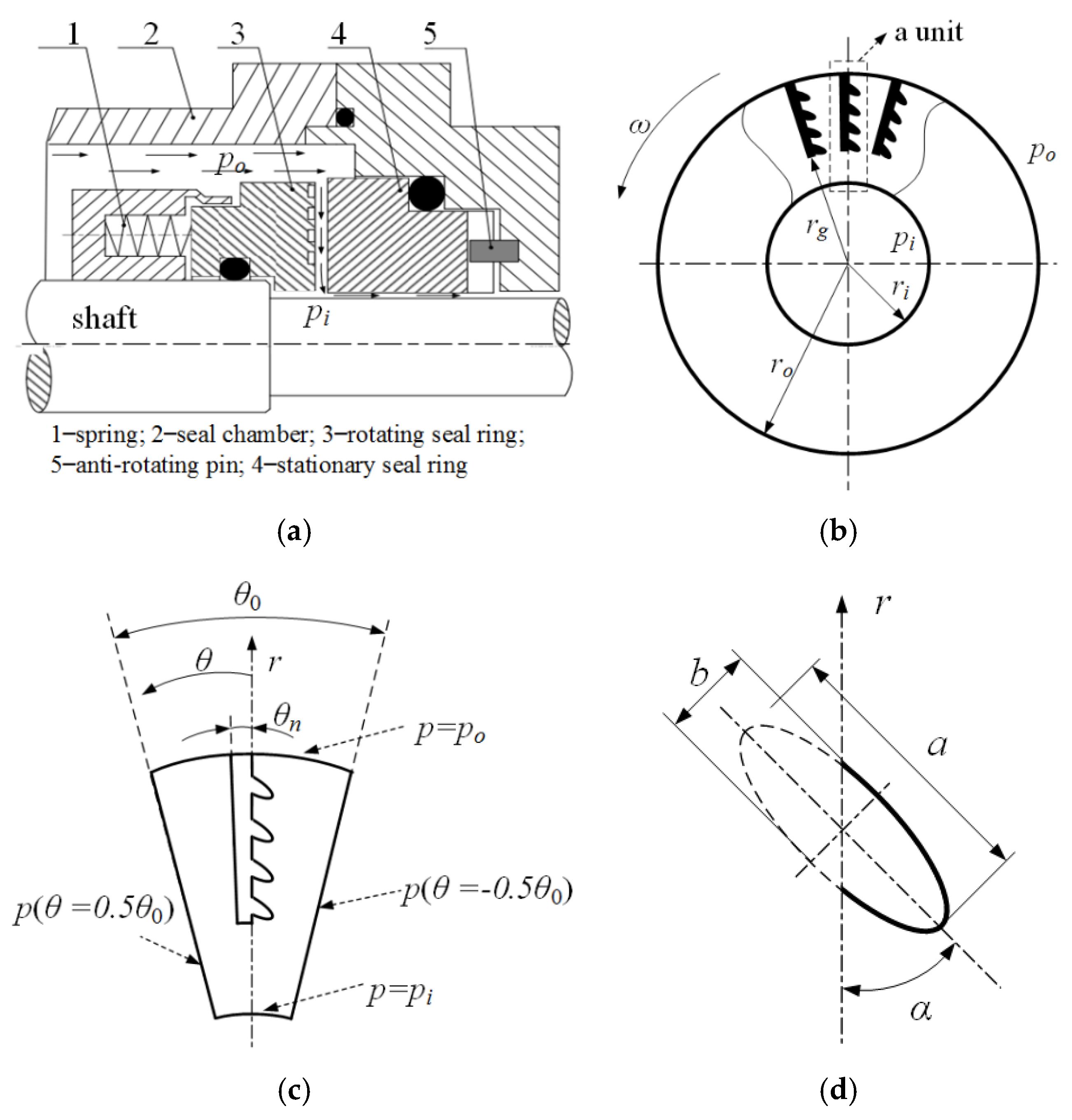
2.1. Semi Salix Leaf Textured Gas Mechanical Seal
2.2. Mathematical Model
2.2.1. Governing Equation and Boundary Condition
- (1)
- Gas film governing equation
- (2)
- Film thickness equation
- (3)
- Boundary conditions
- a.
- Mandatory boundary condition
- b.
- Periodic boundary condition
2.2.2. Parameters of Seal Performance
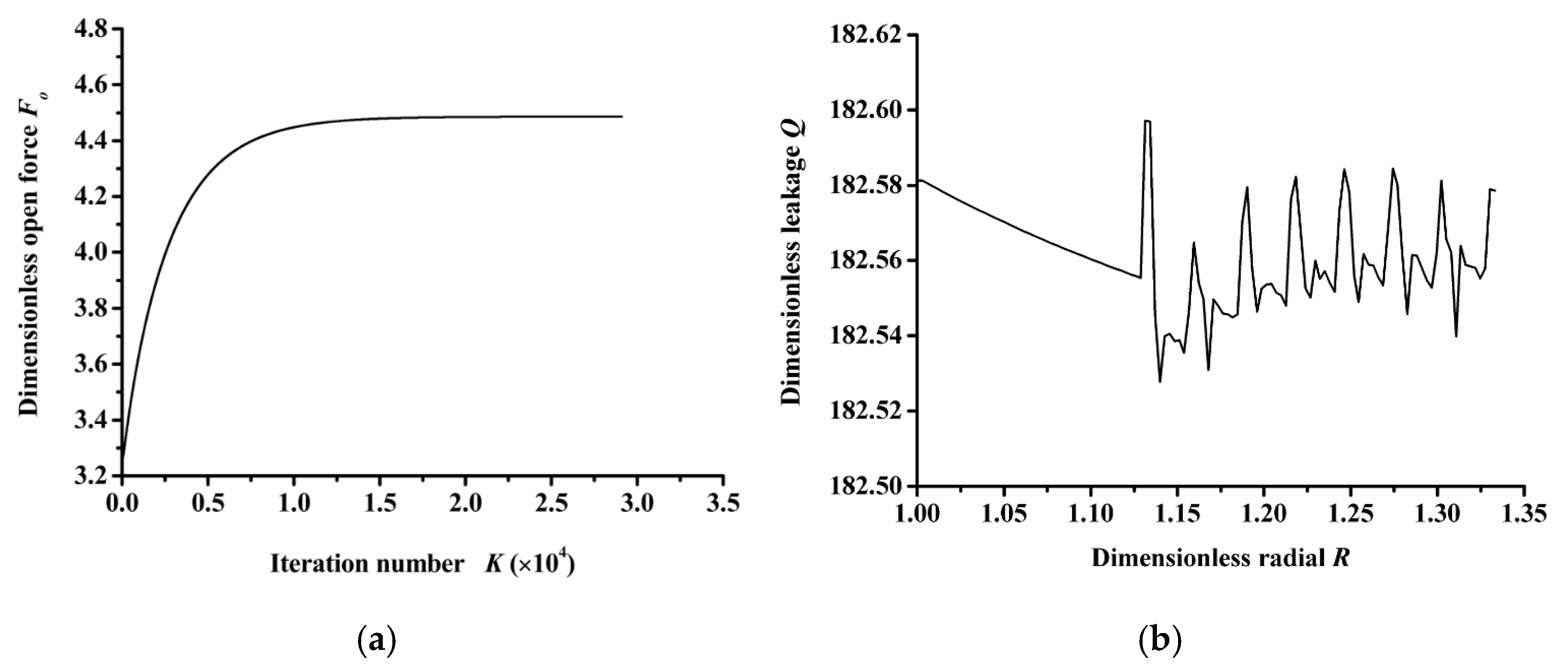
2.3. Calculation Method
- (1)
- Program convergence
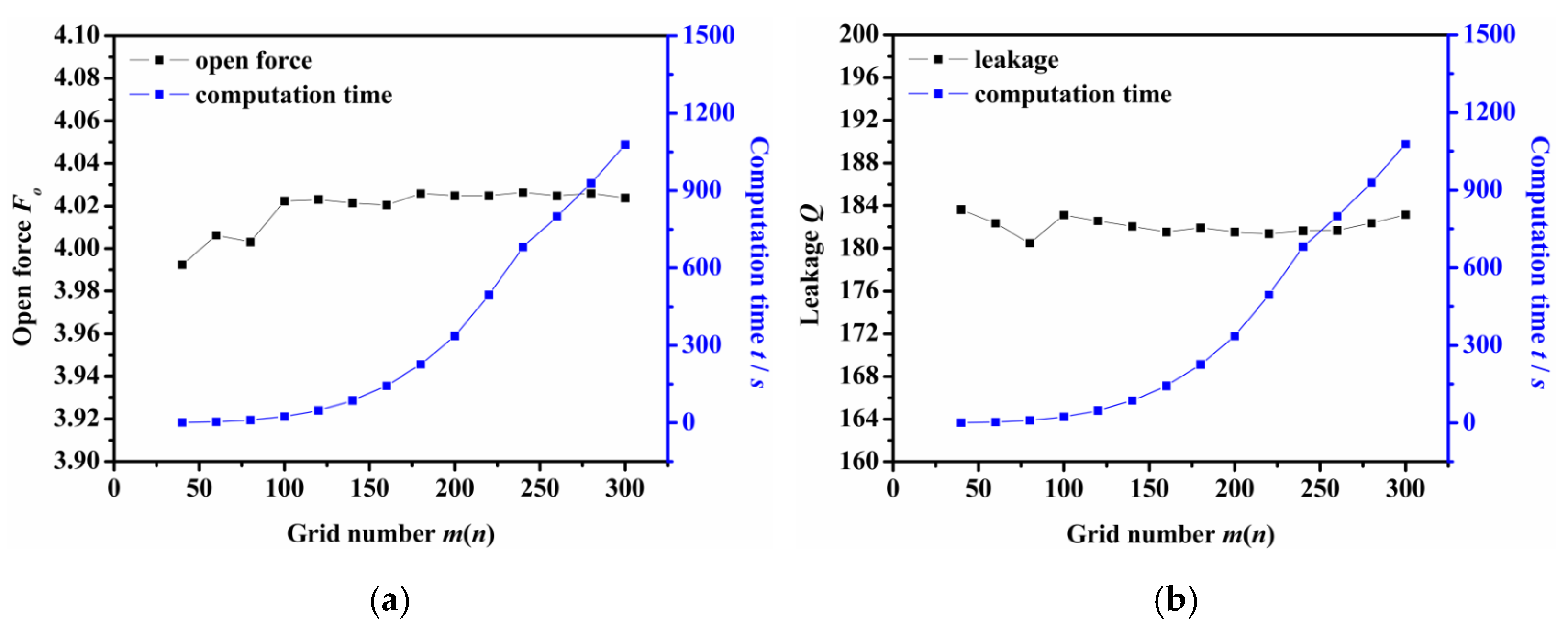
- (2)
- Mesh density
3. Results and Discussion
3.1. Influence of Operation Parameters
- (1)
- Rotation speed
- (2)
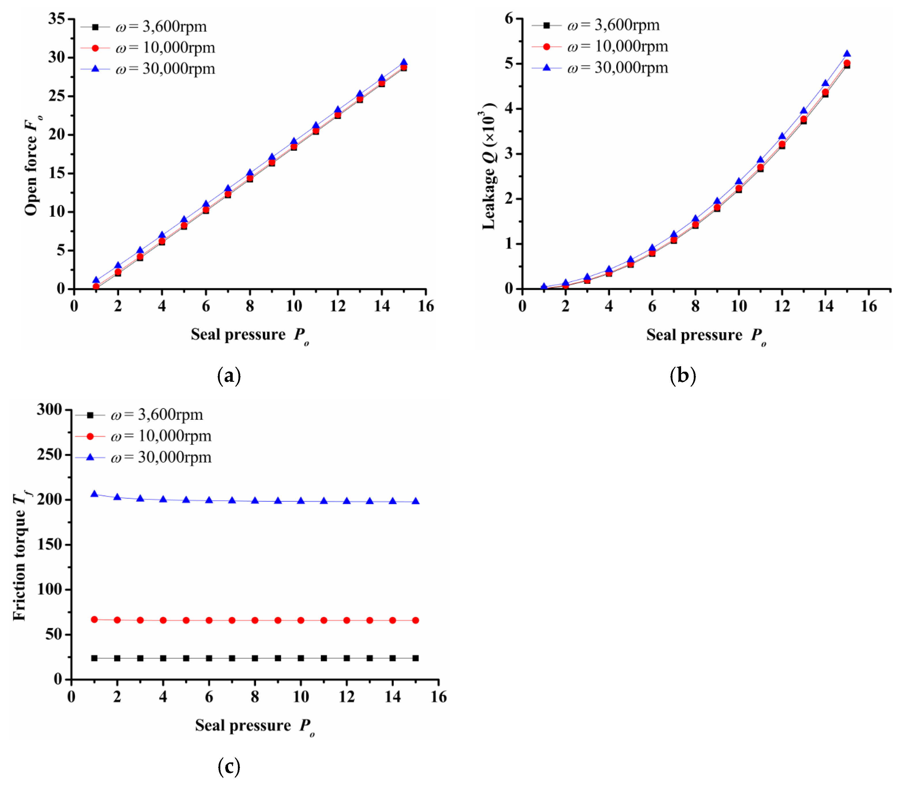
- Seal pressure
- (3)
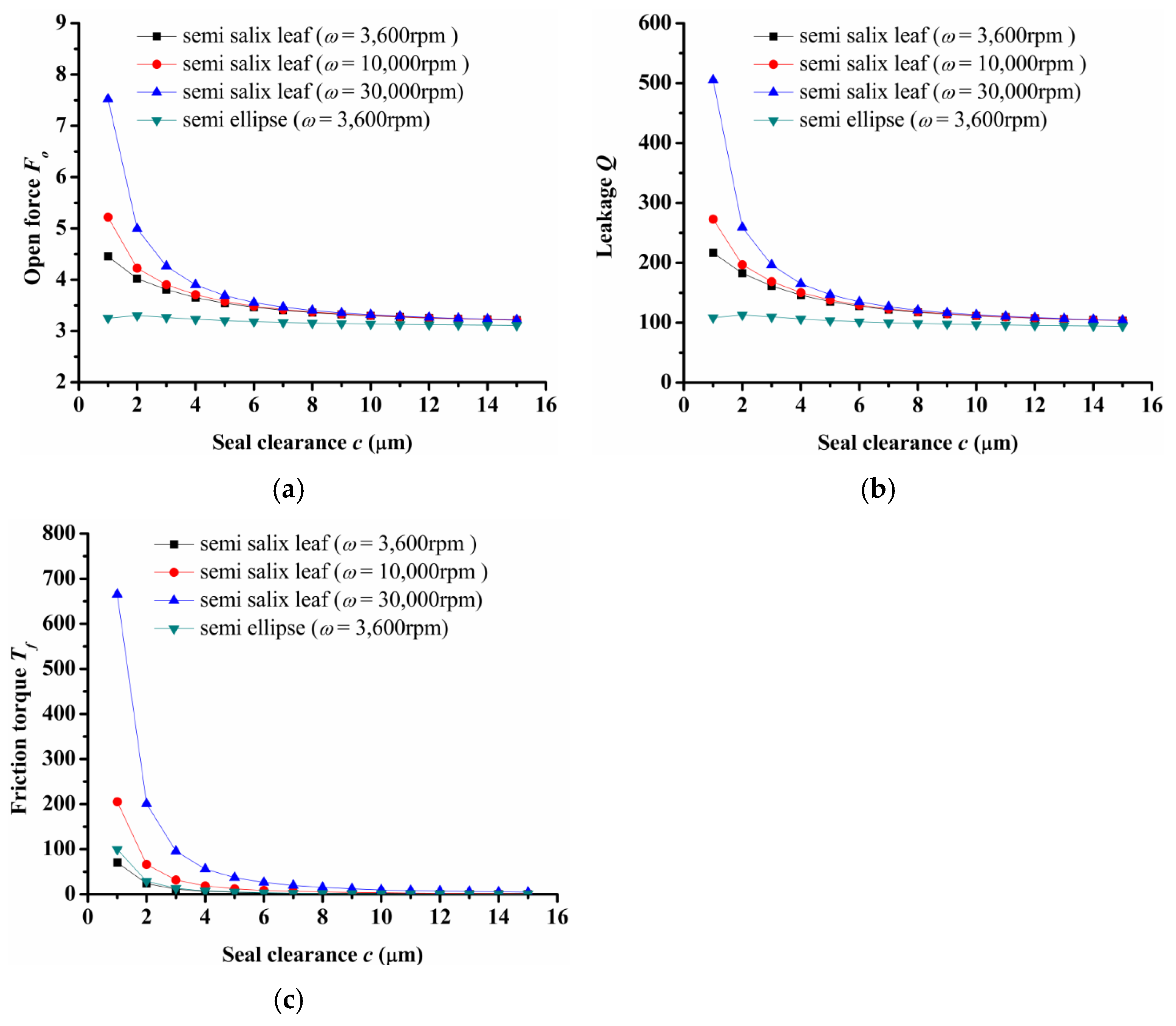
- Seal clearance
3.2. Influence of Texturing Parameters
- (1)
- Inclination angle
- (2)
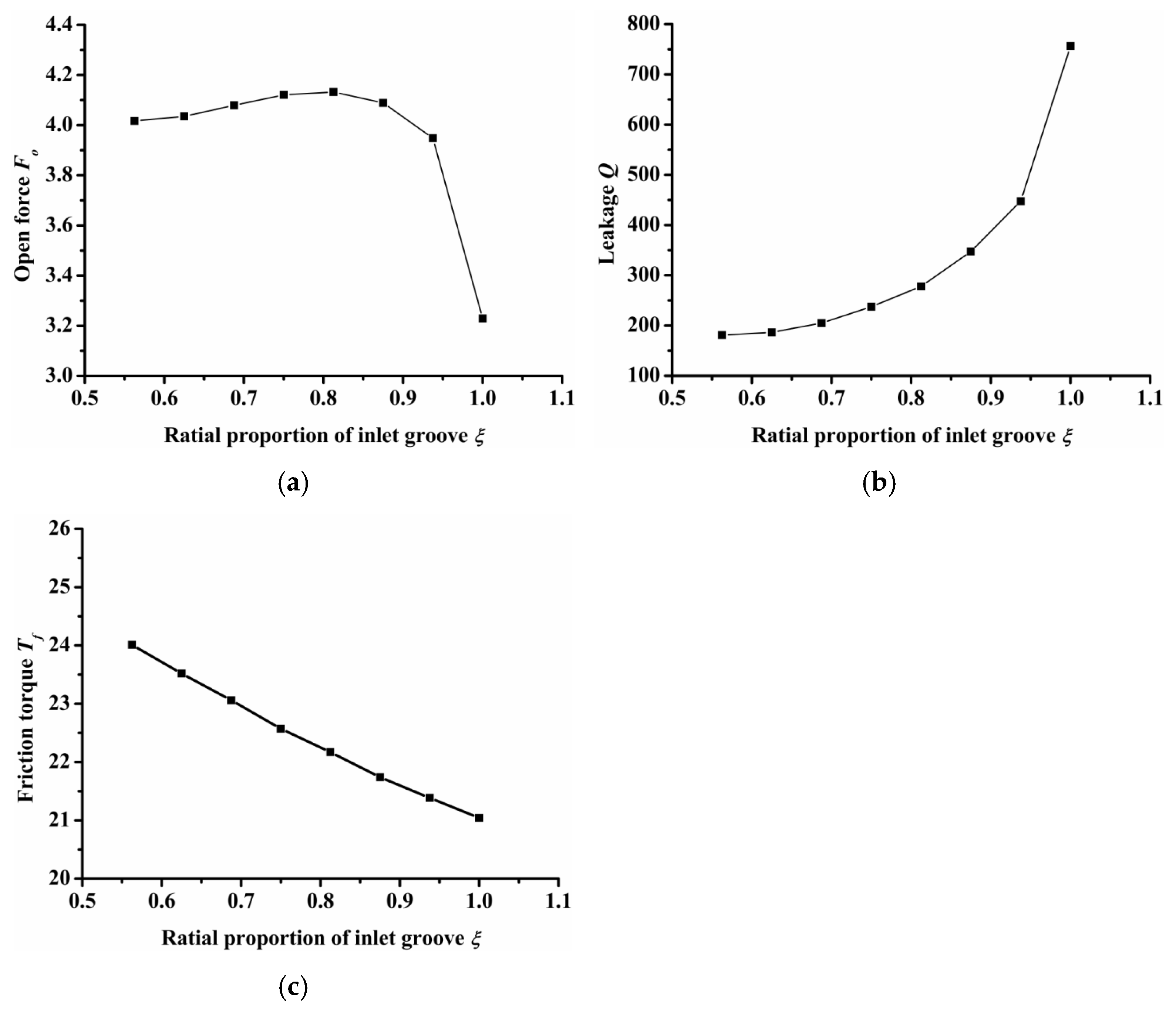
- Radial proportion of inlet groove
- (3)
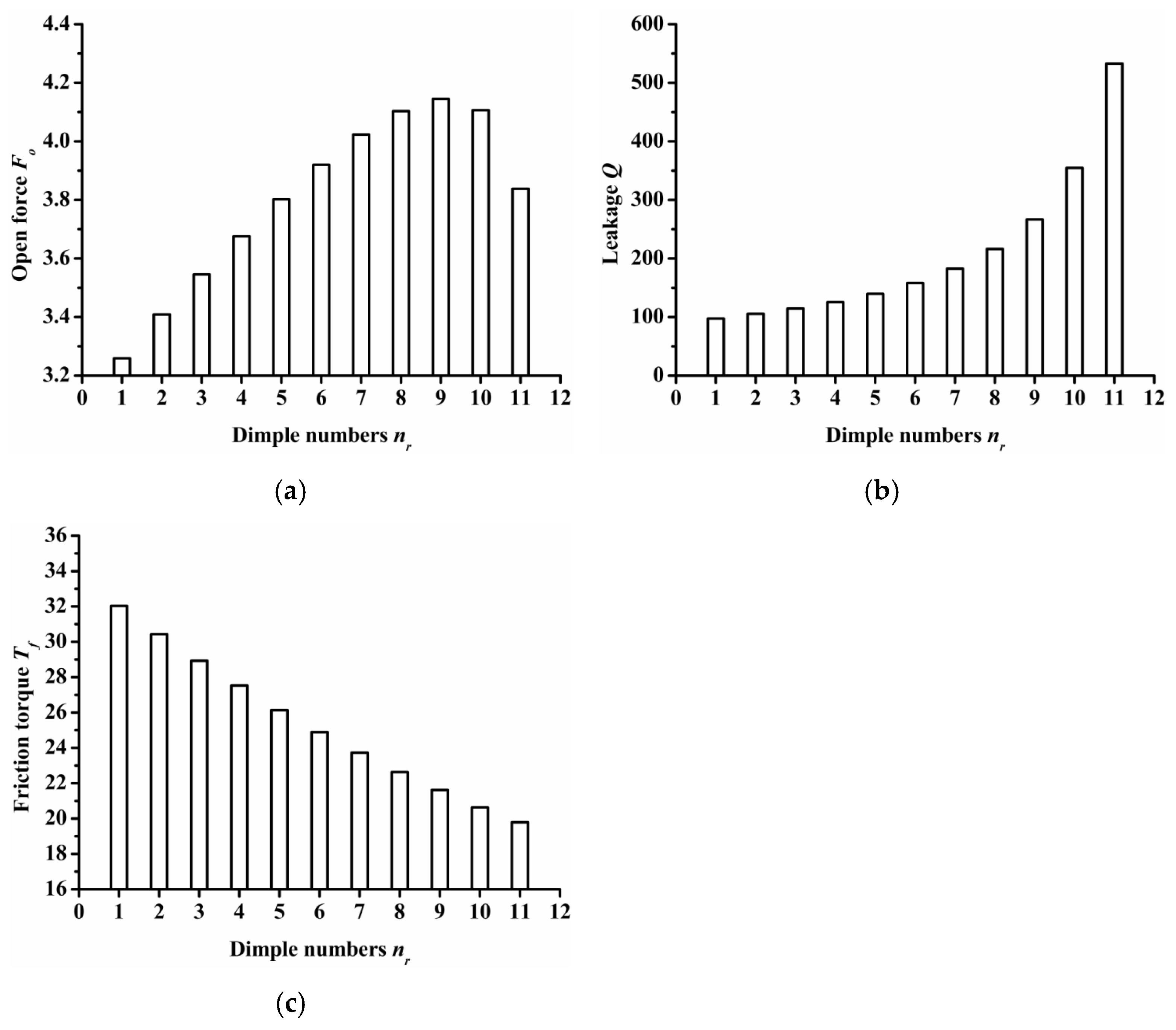
- Dimple numbers
- (4)
- Inlet groove and dimple depth
- (5)
- Inlet groove angle
4. Conclusions
- The semi salix leaf textured gas face seal had larger hydrostatic and hydrodynamic effects than the semi ellipse textured seal because of the effect of the inlet groove. All semi salix leaf textured surfaces had better open performance than the semi ellipse textured surface, which means that the inlet groove plays an important role in improving open performance and consequently decreasing the contact friction during the start-up stage. When the rotation speed was 18,000 rpm, the open force and friction torque of the semi salix leaf textured seal (γ = 4) was about 23% higher and 22% lower, respectively, than that of the semi ellipse textured seal.
- The operation parameters greatly influenced the seal performance of the semi salix leaf textured gas face seal. The open force, leakage, and friction torque increased as the rotation speed increased. This means that the seal faces had excellent opening behavior, which could decrease contact friction and wear during start-up as much as possible. Both open force and leakage increased rapidly with the increase in seal pressure, which was mainly due to the increase in the hydrostatic effect. In addition, the seal pressure had little influence on the friction torque. With the increase in pressure, the friction torque remained almost constant. The open force, leakage, and friction torque decreased sharply as the seal clearance increased, and then almost remained constant when the seal clearance was larger than 8 μm.
- The texturing parameters also influenced the seal performance of the semi salix leaf textured gas face seal. The open force increased as the slender ratio and inclination angle increased. When the inclination angle was 50°, the open force was the largest and the friction torque was low. As the radial proportion of the inlet groove increased, the open force first increased and then decreased. When the radial proportion of the inlet groove was 0.8, the open force reached the maximum value. As the dimple number increased, the open force increased at first and then decreased and reached its maximum value when the dimple number was 9. As the parameters of inlet depth, dimple depth, and inlet width increased, the amount of air intake increased, which will increase the open force, leakage, and decrease the friction torque.
Author Contributions
Funding
Institutional Review Board Statement
Informed Consent Statement
Data Availability Statement
Conflicts of Interest
References
- Wasser, J. Dry seal technology for rotating equipment. Lubr. Eng. 1994, 50, 247–252. [Google Scholar]
- Lai, T.; Gabriel, R.; Mayer, L. Improved performance seals for pipeline applications. Lubr. Eng. 2003, 59, 18–29. [Google Scholar]
- Senatore, A.; Risitano, G.; Scappaticci, L.; D’Andrea, D. Investigation of the tribological properties of different textured lead bronze coatings under severe load conditions. Lubricants 2021, 9, 34. [Google Scholar] [CrossRef]
- Galda, L.; Sep, J.; Olszewski, A.; Zochowski, T. Experimental investigation into surface texture effect on journal bearings performance. Tribol. Int. 2019, 136, 372–384. [Google Scholar] [CrossRef]
- Shen, X.; Tao, G. Tribological behaviors of two micro textured surfaces generated by vibrating milling under boundary lubricated sliding. Int. J. Adv. Manuf. Technol. 2015, 79, 1995–2002. [Google Scholar] [CrossRef]
- Menga, X.; Zhanga, B.; Jing, W.; Qian, Z. Experimental observation on the surface dimple variations in starved EHL of sliding steel-glass point contacts. Tribol. Int. 2017, 105, 166–174. [Google Scholar] [CrossRef]
- Etsion, I.; Burstein, L. A Model for Mechanical Seals with Regular Microsurface Structure. ASME J. Tribol. 1996, 39, 677–683. [Google Scholar] [CrossRef]
- Etsion, I.; Kligerman, Y.; Halperin, G. Analytical and Experimental Investigation of Laser-Textured Mechanical Seal Faces. Tribol. Trans. 1999, 42, 511–516. [Google Scholar] [CrossRef]
- Etsion, I. State of the art in laser surface texturing. ASME J. Tribol. 2005, 127, 248–253. [Google Scholar] [CrossRef]
- Yu, X.Q.; He, S.; Cai, R.L. Frictional Characteristics of Mechanical Seals with a Laser-textured Seal Face. J. Mater. Process. Technol. 2002, 129, 462–466. [Google Scholar] [CrossRef]
- Etsion, I.; Halperin, G. A Laser Surface Textured Hydrostatic Mechanical Seal. Tribol. Trans. 2002, 45, 430–434. [Google Scholar] [CrossRef]
- Song, P.Y.; Wang, Z.G. Theory Analysis of the Liquid Film Pressure between the Faces of the Partial Surface Texturing Mechanical Seals. Lubr. Eng. 2008, 33, 36–39. [Google Scholar]
- Kligerman, Y.; Etsion, I. Analysis of the Hydrodynamic Effects in a surface Textured Circumferential gas seal. Tribol. Trans. 2001, 44, 472–478. [Google Scholar] [CrossRef]
- McNikel, A.D.; Etsion, I. Near-contact Laser Surface Textured Dry Gas Seals. ASME J. Tribol. 2004, 126, 788–794. [Google Scholar]
- Feldman, Y.; Kligerman, Y.; Etsion, I. A Hydrostatic Laser Surface Textured Gas Seal. Tribol. Lett. 2006, 22, 21–28. [Google Scholar] [CrossRef]
- Feldman, Y.; Etsion, I. Stiffness and Efficiency Optimization of A Hydrostatic Laser Surface Textured Gas SeaL. ASME J. Tribol. 2007, 129, 407–410. [Google Scholar] [CrossRef]
- Peng, X.D.; Du, D.B.; Sheng, S.E.; Li, J.Y. Effect of Face Asperity Geometry on Performance of a Liquid Lubricated Face Seal. Tribology 2007, 27, 352–356. [Google Scholar]
- Bai, S.X.; Peng, X.D.; Li, Y.F.; Sheng, S.E. A Hydrodynamic Laser Surface Textured Gas Mechanical Face Seal. Tribol. Lett. 2010, 38, 187–194. [Google Scholar] [CrossRef]
- Li, Y.F.; Sheng, S.E.; Bai, S.X.; Peng, X.D. Experiment of a Hydrodynamic Multi-Pored Face Gas Seal at Zero Pressure. Lubr. Eng. 2010, 35, 8–11. [Google Scholar]
- Xie, J.; Bai, S.X. Hydrodynamic effect of non-closed elliptical grooves of bi-directional rotation gas face seals. Ind. Lubr. Tribol. 2020, 72, 369–377. [Google Scholar] [CrossRef]
- Shellef, R.A.; Johnson, R.P. A bi-directional gas face seal. Tribol. Trans. 1992, 35, 53–58. [Google Scholar] [CrossRef]
- Basu, P. Analysis of a radial groove gas face seal. Tribol. Trans. 1992, 35, 11–20. [Google Scholar] [CrossRef]
- Wen, S.Z.; Huang, P. Principles of Tribology, 4th ed.; Tsinghua University Press: Beijing, China, 2017; pp. 22–25. [Google Scholar]


Publisher’s Note: MDPI stays neutral with regard to jurisdictional claims in published maps and institutional affiliations. |
© 2021 by the authors. Licensee MDPI, Basel, Switzerland. This article is an open access article distributed under the terms and conditions of the Creative Commons Attribution (CC BY) license (https://creativecommons.org/licenses/by/4.0/).
Share and Cite
Bai, L.; Zhang, P.; Khan, Z.A. Semi Salix Leaf Textured Gas Mechanical Face Seal with Enhanced Opening Performance. Materials 2021, 14, 7522. https://doi.org/10.3390/ma14247522
Bai L, Zhang P, Khan ZA. Semi Salix Leaf Textured Gas Mechanical Face Seal with Enhanced Opening Performance. Materials. 2021; 14(24):7522. https://doi.org/10.3390/ma14247522
Chicago/Turabian StyleBai, Linqing, Pengcheng Zhang, and Zulfiqar Ahmad Khan. 2021. "Semi Salix Leaf Textured Gas Mechanical Face Seal with Enhanced Opening Performance" Materials 14, no. 24: 7522. https://doi.org/10.3390/ma14247522
APA StyleBai, L., Zhang, P., & Khan, Z. A. (2021). Semi Salix Leaf Textured Gas Mechanical Face Seal with Enhanced Opening Performance. Materials, 14(24), 7522. https://doi.org/10.3390/ma14247522