Abstract
RuAl thin films possess a high potential as a high temperature stable metallization for surface acoustic wave devices. During the annealing process of the Ru-Al films, AlO is formed at the surface of the films even under high vacuum conditions, so that the composition of a deposited RuAl film is shifted to a Ru-rich alloy. To compensate for this effect, the Al content is systematically increased during the deposition of the Ru-Al films. Three Al-rich alloys—RuAl, RuAl and RuAl—were analyzed concerning their behavior after high temperature treatment under high vacuum and air conditions in comparison to the initial RuAl sample. Although the films’ cross sections show a more homogeneous structure in the case of the Al-rich films, the RuAl phase formation is reduced with increasing Al content.
1. Introduction
High temperature stable metallizations attract attention for a wide field of applications, especially in the area of high temperature stable sensors and, to a minor degree, also as electrodes for the high temperature characterization of acoustic properties of piezoelectric crystals. Recently, various metals, alloys and compounds have been characterized and optimized concerning their high temperature (up to 1000 C) applicability [1,2,3,4]. One of the materials described as promising for high temperature applications up to 800 C under high vacuum conditions is the RuAl alloy [5,6,7,8]. However, during its annealing at high temperature, Al gets oxidized even under high vacuum conditions and a 15–20 nm thick AlO layer is formed at the sample surface (annealing temperature: 800 C, annealing time: 10 h) [7,8,9]. Due to the formation of the AlO, the overall content of Al in the film after the annealing is reduced as compared to the as-deposited state. This means that if a stoichiometric RuAl film is deposited, after the annealing, the composition is shifted to an Ru-rich alloy. From former investigations of 110 nm thick RuAl films on Si/SiO substrates, which where annealed at 800 C for 10 h under high vacuum conditions, we estimate that the formed AlO cover layer contains up to about 20 at % of the Al of the initially deposited RuAl film.
Investigation of the oxidation behavior of thicker RuAl films (200–600 nm) [10,11] as well as of bulk samples [12,13,14] reveal a complicated, partly multilayered oxide scale on top of the samples consisting of alternating AlO and Ru layers.
On the other hand, dense AlO cover layers are known to act as passivation layers, so that the formation of an AlO thin layer at the film surface might also improve the long-term stability of the subjacent film. One way to compensate for the lack in Al due to some formation of AlO is to deposit the Ru-Al alloy with increased Al content. This paper reports on the effects of the increased Al content on the RuAl phase formation and high temperature stability of RuAl () thin films.
2. Experimental Section
Ru-Al thin films with a constant thickness of 110 nm in the as-deposited state have been deposited by magnetron co-sputtering from elemental Ru (purity: 99.95%) and Al (purity 99.9995%) targets on thermally oxidized Si substrates (Si/SiO (for details of deposition, see [7])). Besides the preparation of the stoichiometric RuAl phase, samples with a higher content of Al were prepared—namely, RuAl with . The composition was changed by increasing the sputtering power of Al by 20%, 50% and 100%, resulting in the above described compositions in the as-deposited state.
After preparation, the obtained atomic compositions were checked with glow discharge optical emission spectroscopy (GDOES, GDA 750 HR, Spectruma Analytik GmbH, Hof, Germany). The instrument was calibrated using two different RuAl bulk standards in combination with energy dispersive X-ray spectroscopy (EDX) in a scanning electron microscope (SEM, Zeiss Ultra Plus, Carl Zeiss Microscopy GmbH, Jena, Germany). Applying the determined calibration, the measurements of the various co-sputtered thin films showed that the Ru-content in the as-deposited films was systematically 5 at % higher than intended; a deviation which is, in this case, within the measurement precision of the applied methods, so that the annotation is kept as above mentioned. In the following, the composition RuAl () always refers to the as-deposited state.
After deposition, the samples were annealed at 600 C (air), 800 C (air and high vacuum) or 900 C (air and high vacuum) for 10 h. During the treatment under high vacuum conditions, the pressure in the oven was below 10 mbar.
The phase formation before and after the heat treatment was investigated by X-ray diffraction (XRD, Philips X’Pert PW3040/00, Co-K, PANalytical, Almelo, The Netherlands) in Bragg Brentano geometry. The surface morphology was imaged by SEM. Cross sections of the layer stacks have been prepared by the focussed ion beam technique (FIB, Zeiss 1540 XB CrossBeam, Carl Zeiss Microscopy GmbH) and have been imaged by SEM.
The global chemical composition was analyzed by Auger electron spectroscopy (AES, JEOL JAMP-9500F Field Emission Auger Microprobe, JEOL (Germany) GmbH, Freising, Germany). The measurement of depth profiles was realized by sputtering with Ar ions for 60 s with an ion beam at 1 keV and a current of A (corresponding to a milling rate of 6.6 nm/min for amorphous SiO). For some samples, it was necessary to increase the ion energy to 2 keV (corresponding to a milling rate of 15–20 nm/min of SiO). In the following, this is denoted for the respective samples. Concentration quantification was done using single element standard sensitivity factors [15]. Additionally preferential sputtering during ion bombardement can alter the surface concentration; thus, the absolute measured concentrations may differ from the bulk ones. However, relative concentration changes after thermal treatment can always be followed. The sputtered area is about 1 mm and the measurement region for the AES within this is about m.
Measurements of the electrical resistance were carried out by using the van der Pauw method [16] for thin films. Several measurements were done with constant current of 5 and 10 mA and alternating direction of the electric current using a constant current source and a nanovoltmeter (2182A–Nanovoltmeter, KEITHLEY-TEKTRONIX, Inc., Beaverton, OR, USA) for voltage measurement.
The analysis of the microstructure was performed by high-angle annular dark field scanning transmission electron microscopy (HAADF-STEM, Technai F30, FEI company, Hillsboro, OR, USA). The image contrast is sensitive to the chemical composition. The local chemical composition was revealed by energy dispersive X-ray spectroscopy (EDX, EDAX Company, Mahwah, NJ, USA) in the same instrument.
3. Results
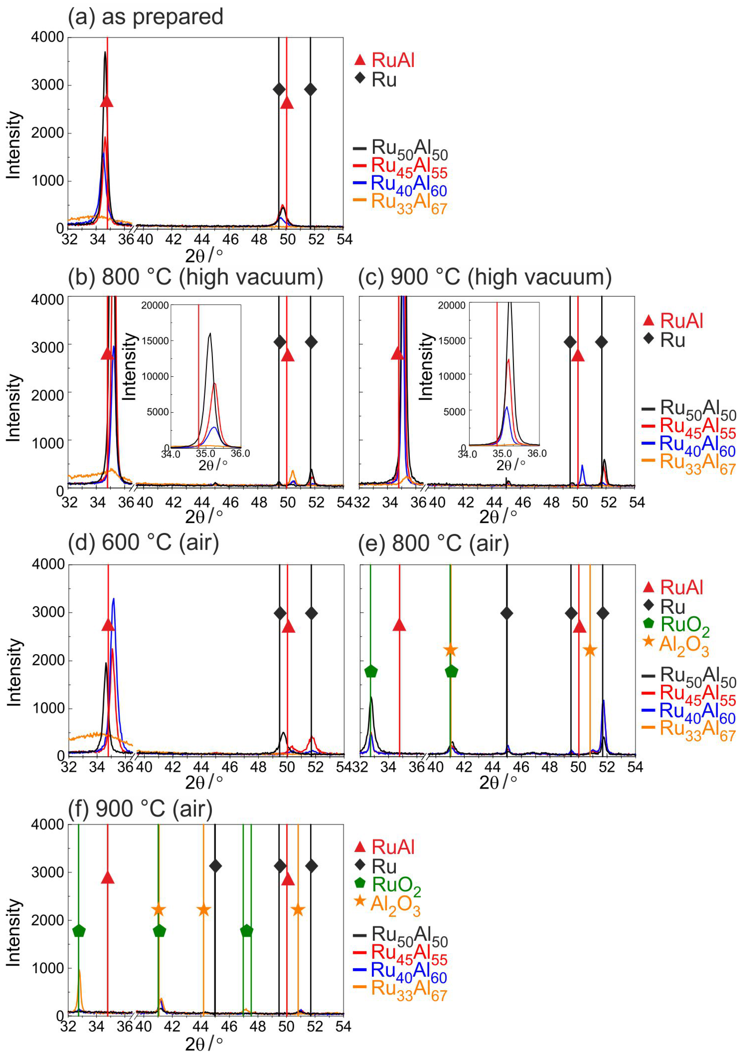
3.1. Phase Formation
Figure 1 summarizes the results of the XRD measurements at different annealing temperatures between 600 and 900 C in air or under high vacuum conditions.
Figure 1.
X-ray diffraction (XRD) measurements (CoK) of samples with the different compositions RuAl () (a) after preparation and after heat treatment for 10 h at (b) 800 C under high vacuum; (c) 900 C under high vacuum; (d) 600 C in air; (e) 800 C in air and (f) 900 C in air.
For the as-prepared state (Figure 1a), mainly (100) RuAl reflexes at a position of 34.8 are visible. The highest intensity is reached for the RuAl sample. In contrast to this, the RuAl sample only shows a very small broad peak indicating amorphous phases. The RuAl (110) reflex is tiny for all samples and also not visible for the RuAl film.
Annealing under high vacuum conditions (Figure 1b,c) leads to a strong increase in the RuAl (100) intensity (a zoom-in of the RuAl (100) peak is shown in the inset). It can be seen that the reflex shifts to higher angles and that the intensity strongly depends on the composition. The lower the Al content, the higher is the intensity of the RuAl (100) reflex. Annealing at 900 C leads to higher RuAl (100) intensities than the annealing at 800 C. For the RuAl sample, only a very small RuAl (100) peak is visible for both temperatures. A small RuAl (110) reflex appears at 800 C for this sample, whereas at 900 C, this reflex is only visible for the RuAl film.
In addition to the RuAl reflexes, after the heat treatment, small Ru (101) reflexes also appear at a position of 51.7 for the RuAl and RuAl samples.
Figure 1d–f presents the results of the XRD measurements after the heat treatment in air. Annealing at 600 C in air leads to a decrease of the RuAl (100) peak of the RuAl film. There is no change in intensity for the RuAl sample, but a clear increase of the peak intensity of the RuAl film is observed. In the case of RuAl, there is a slight increase of the broad peak. An Ru (002) peak evolves for the RuAl sample and an Ru (101) peak for RuAl.
The diffraction pattern changes clearly after the heat treatment at 800 C in air. The RuAl reflexes disappear for all samples and new phases appear. At of 32.4, the RuO (110) reflex formed, which is strongest for the RuAl sample and nearly the same for the other samples. The small peak at of 41 can be ascribed to RuO or AlO. A strong Ru reflex appears for RuAl and RuAl, which is much smaller for the other two samples.
Finally, after the heat treatment at 900 C in air, only for the RuAl sample is an RuO (110) reflex present besides some very tiny RuO/AlO peaks.
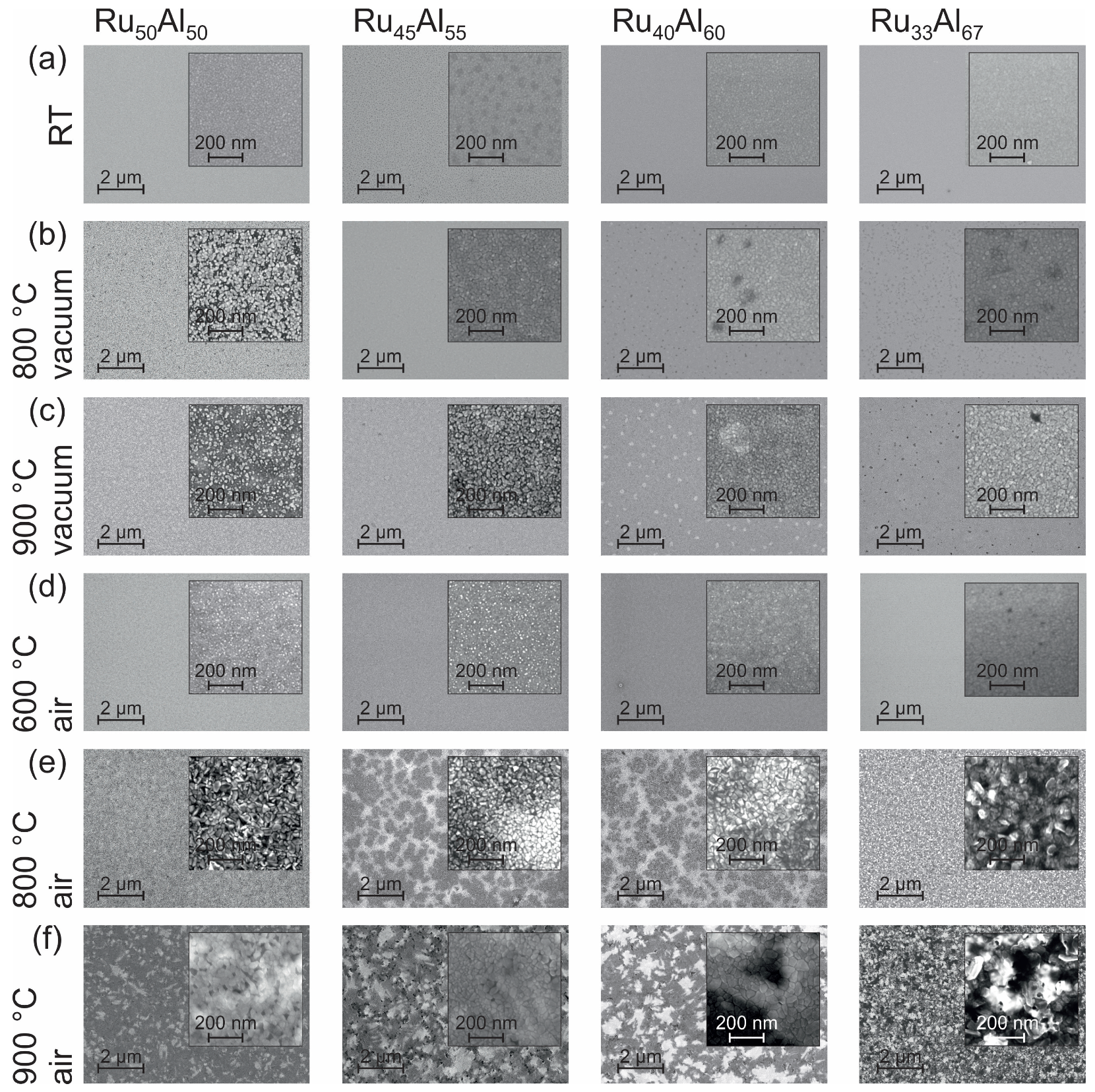
3.2. Morphology
The surface morphology can be seen in the SEM images (inLens detector at 20 kV) summarized in Figure 2. At room temperature (RT) (Figure 2a), all samples appear homogeneous. Only in the case of RuAl is the surface a little bit spotted.
Figure 2.
Scanning electron microscopy (SEM) inLens (20 kV) images showing the surface morphology of the samples with the different compositions RuAl, RuAl, RuAl and RuAl (a) after preparation and after heat treatment for 10 h at (b) 800 C; (c) 900 C under high vacuum, as well as (d) 600 C; (e) 800 C and (f) 900 C in air.
Annealing the samples at 800 C under high vacuum conditions (Figure 2b) only leads to minor changes. In the case of RuAl, we find bright separated features in a darker matrix. For RuAl and RuAl, darker areas are present.
The heat treatment at 900 C in high vacuum (Figure 2c) results in a further separation of the bright structures in the RuAl film and a starting separation of the features in the RuAl sample. Bright areas are formed in the RuAl film while the dark spots in RuAl become clearer.
The annealing procedure at 600 C under air conditions (Figure 2d) leads to the formation of very small bright spots at the sample surface. The density of those spots decreases with increasing Al content and becomes zero for the RuAl film.
The film morphology after the heat treatment at 800 C in air (Figure 2e) is completely different as compared to the previous samples. Larger structures with a high roughness have formed. In contrast to the films with a composition of RuAl and RuAl, those with RuAl and RuAl possess large dark areas embedded in a brighter matrix.
The 900 C annealing under air (Figure 2f) shows a further modification of the morphology found for the 800 C air annealed samples. A patchy pattern is now also clearly visible for the RuAl sample. The surface appears smoother than after the 800 C air annealing. The samples RuAl and RuAl show also a pattern consisting of irregular bright and dark areas. Within these areas, there are also larger structures that appear very smooth. The most irregular surface structure with a strong contrast is found for the RuAl film.
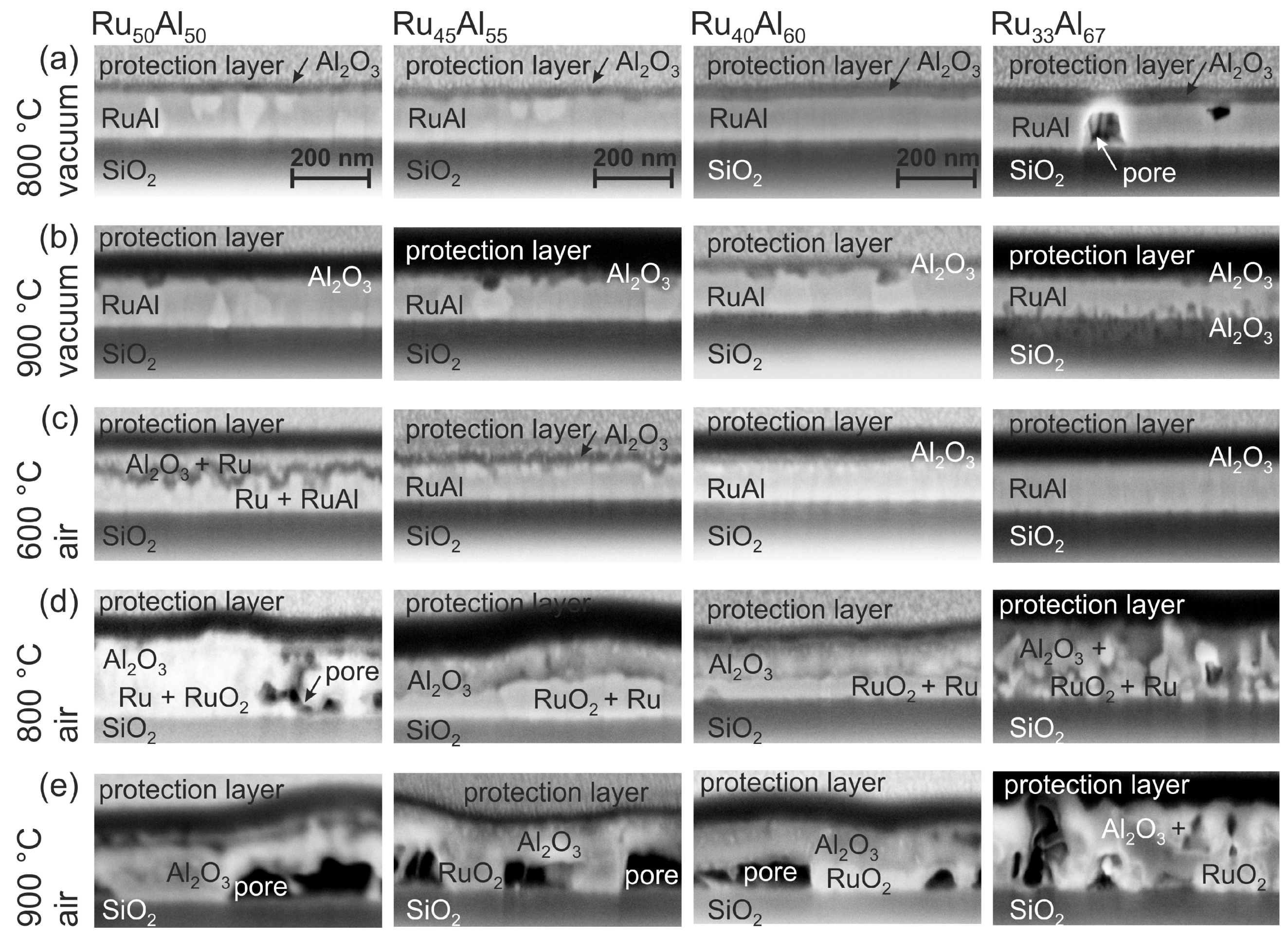
3.3. Film Architecture
SEM images of the cross sections of the films are presented in Figure 3. The labeling of the different layers was done according to the results of the AES and TEM/EDX measurements, which are discussed in the following sections. Clear differences between the various samples and annealing conditions are visible.
Figure 3.
SEM inLens images (3 kV) of the focussed ion beam (FIB) cross sections of the samples with the different compositions RuAl, RuAl, RuAl and RuAl after heat treatment for 10 h at (a) 800 C; (b) 900 C under high vacuum, as well as (c) 600 C; (d) 800 C and (e) 900 C in air. The images are labeled according to the results of the Auger electron spectroscopy (AES) and transmission electron microscopy/energy dispersive X-ray spectroscopy (TEM/EDX) measurements.
The cross section images of the samples annealed at 800 C under high vacuum (HV) conditions (Figure 3a) show randomly distributed bright grains in a matrix for the RuAl sample. The number of those grains is reduced for RuAl. No grain structure is visible in case of RuAl and RuAl; however, pores are formed in the latter film. These pores might be the origin of the dark spots that are visible in the SEM surface images.
After the heat treatment at 900 C under high vacuum (Figure 3b), still bright grains are present in the case of RuAl and RuAl. A grain structure is now also visible in the RuAl sample. For these three films, small dark areas appear in the upper region of the film. In the case of the RuAl film, dark features have developed at the interface to the substrate. A cross section image of a more extended sample region of the RuAl film confirms pores also in this sample, which explain the dark spots in the surface images.
Annealing at 600 C under air conditions (Figure 3c) results in the case of RuAl and RuAl in a multilayer structure. There is a very irregular dark layer in the upper region of the film. This layer is much smoother in case of RuAl. An additional thin bright layer is visible below the darker one. Such interlayers are not distinguishable in the other two systems. For RuAl, the images reveal a thin layer of bright grains at the sample surface, while the sample with the highest Al content appears completely homogeneous.
The heat treatment at 800 C in air (Figure 3d) leads to pores in the lower region of the RuAl film. In contrast to this, the RuAl and RuAl samples are continuous with a two-layer structure. There are larger bright grains in the lower part of the film covered by a darker, more heterogeneous layer. The thickness of the lower layer changes laterally, which might also explain the differences in brightness in the SEM surface images. A completely inhomogeneous morphology has formed for the film with the RuAl composition. The large surface roughness that results from these grains confirms the roughness visible in the surface images.
The annealing process at 900 C in air (Figure 3e) results in the growth of the pores in the lower part of the RuAl, RuAl and RuAl sample. These pores are covered by a continuous thick layer. The presence of these large pores also in this case explains the different structures, which are visible in the images taken of the sample surface. The RuAl sample behaves differently. In contrast to the other samples, this film is still quite compact with only small pores distributed randomly over the whole film thickness.
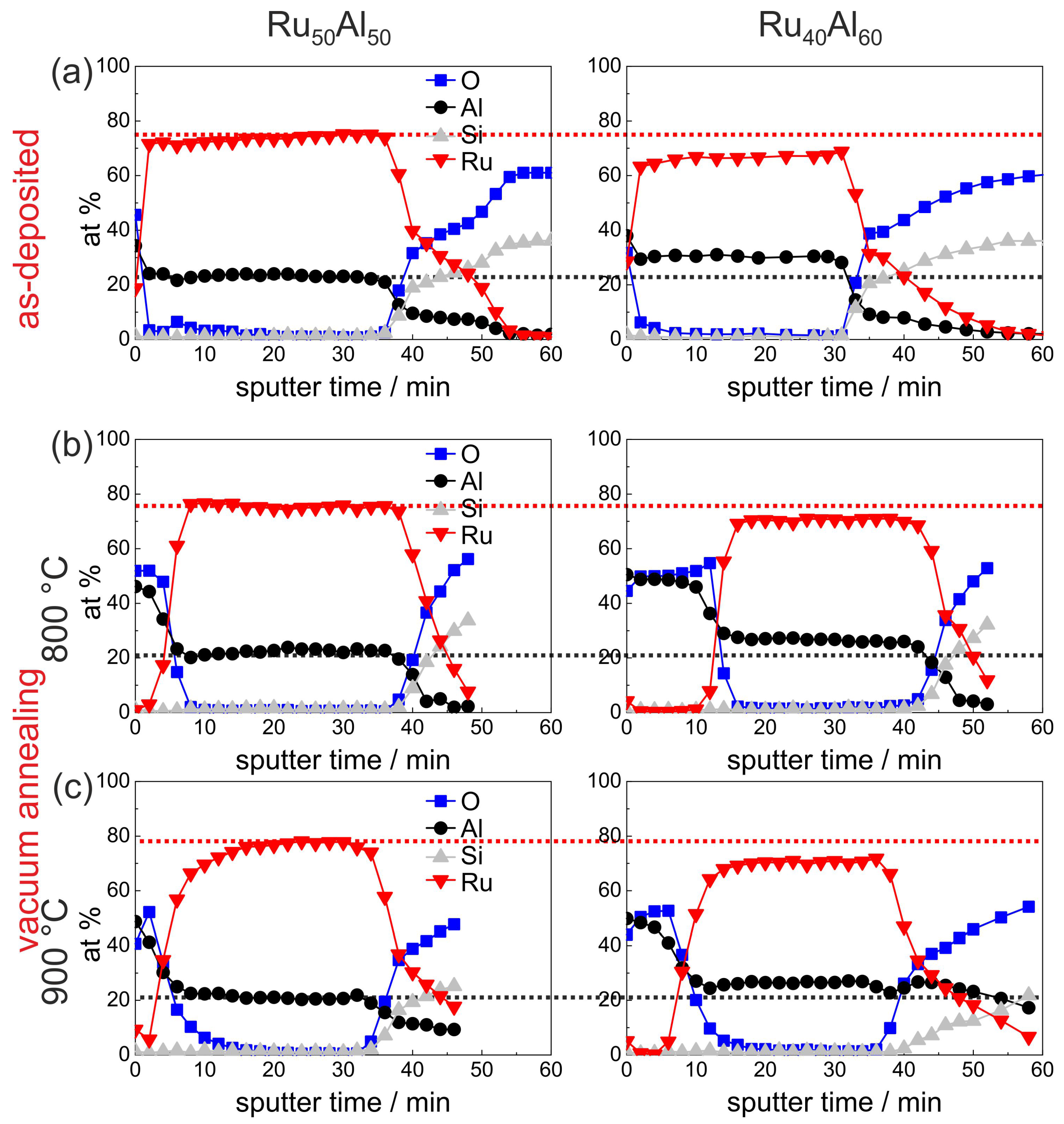
3.4. Film Chemistry
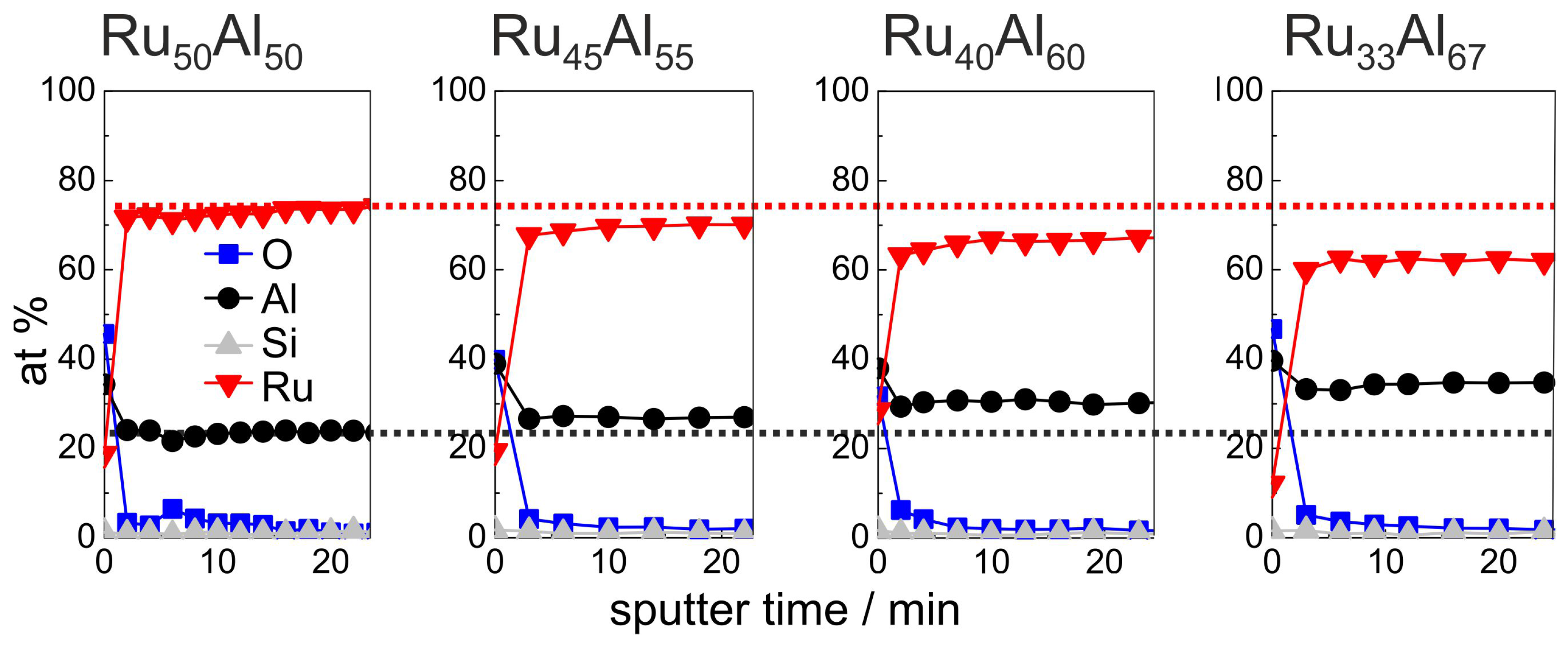
In the following, the results of the AES measurements concerning the film chemistry will be discussed. It has to be remarked that the AES results show mean values of the composition, since the layers are not homogeneous, e.g., Ru-rich grains and the RuAl-matrix as well as AlO and Ru or RuO grains after annealing in air are measured simultaneously. Therefore, the AES results have to be interpreted with support of the XRD results and cross-section images.
Figure 4 summarizes the initial 24 min of the AES measurements (for complete measurements, see Figure 7a) of the as-deposited samples, which verify the increasing Al and decreasing Ru content in the sample series, which was intended by the deposition. Additionally, the existence of a very thin AlO oxide layer at the film surface is proven. However, the measured ratio between Ru and Al differs clearly from the deposited one, i.e., the absolute at % values that are derived from the AES measurements do not depict the actual composition. Further AES and XPS (X-ray photoelectron spectroscopy) investigations have shown that this is caused mainly by strong preferential sputtering effects in the Ru-Al-sytem [17], so that quantitative conclusions are not possible. However, the results allow a qualitative comparison between the samples.
Figure 4.
AES measurements of the as deposited samples with the different compositions RuAl, RuAl, RuAl and RuAl. The red (black) dotted line marks the Ru (Al) content in the reference RuAl sample to visualize the difference to the other samples.
The development of the sample chemistry after the various annealing procedures will be discussed based on the reference RuAl and exemplary RuAl samples. The overview image Figure 7, which summarizes the AES measurements of all samples and for all annealing procedures, shows that the behavior of the RuAl sample is between these two films. For the sample with the highest Al content, additional effects are visible which will be discussed subsequently. 
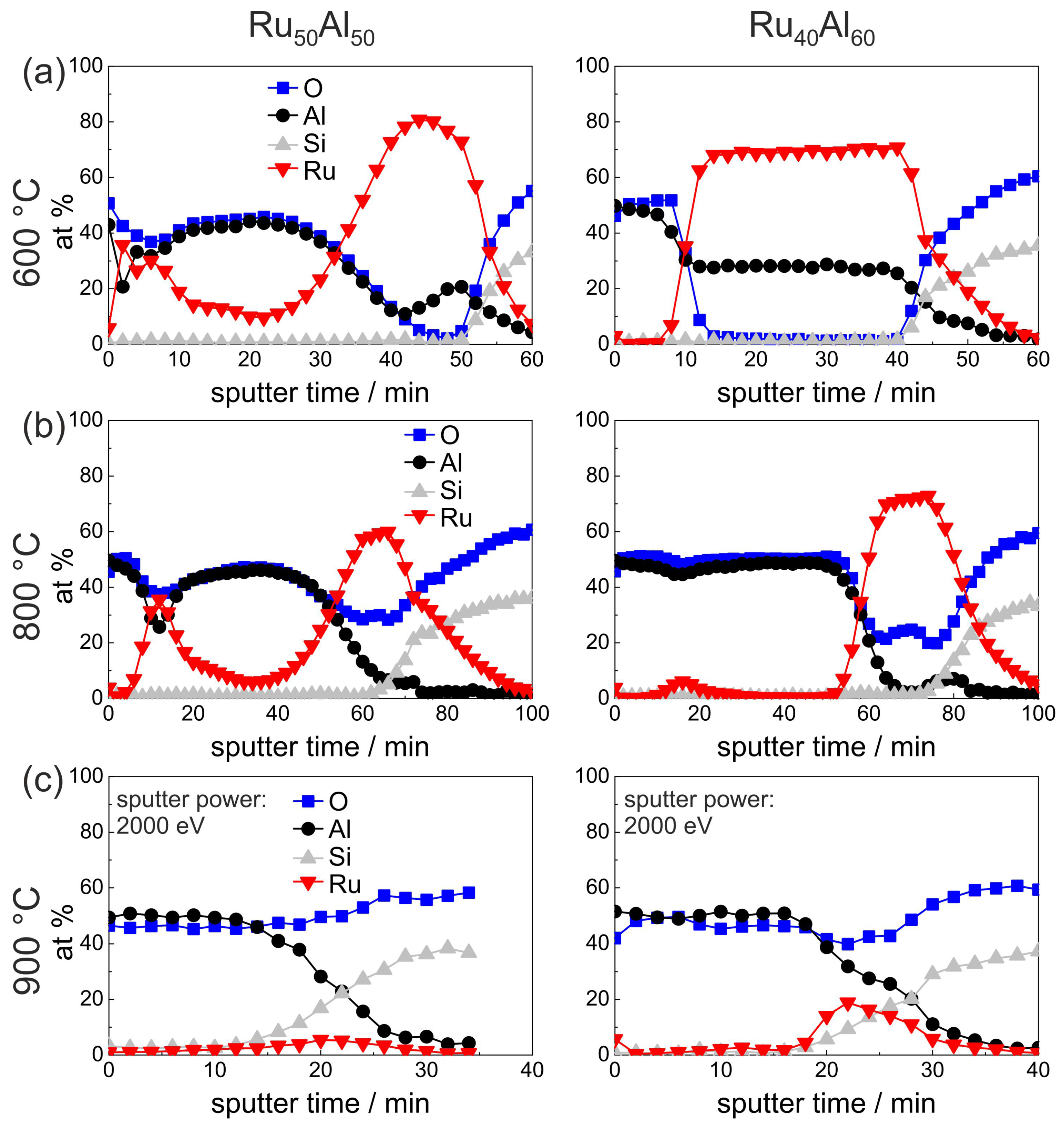
Figure 5 presents the measurements of the as-deposited and vacuum annealed state of the RuAl and RuAl samples. The results of the as-deposited films are repeated since they serve as a reference for the annealed samples.
Figure 5.
AES measurements of the RuAl and RuAl samples in (a) the as-deposited state and after annealing for 10 h in high vacuum at (b) 800 C and (c) 900 C. The red (black) dotted line marks the Ru (Al) content of the as-deposited reference RuAl sample to visualize the difference to the other samples.
Annealing at 800 C under HV conditions (Figure 5b) leads to the formation of an AlO layer on top of the film. This layer is much thicker for the film with higher Al content (16 min of sputtering AlO compared to 8 min). As a consequence of this oxide layer formation, the mean value of the measured Ru content increased slightly. In the case of the RuAl sample, the mean Ru content results from Ru-rich grains and a Ru-Al matrix (see Figure 3a), while such an inhomogeneity is not visible for the RuAl film.
Annealing at 900 C under HV conditions (Figure 5c) results in a broader transition between the AlO layer on top of the film and the Ru-Al matrix in the case of the RuAl sample. In contrast to this, in the case of the RuAl film, the AlO cover layer is thinner as compared to the 800 C case. Here, a different oxidation kinetics at 800 C as compared to 900 C has to be assumed, which leads to a more stable and more protective and with this thinner AlO layer.
The AES results of the air-annealed RuAl and RuAl films are presented in Figure 6. A clear difference is visible after annealing at 600 C in air between both samples. While the RuAl film retains the bilayer AlO/Ru-Al/substrate architecture, the structure of the RuAl sample is completely different. Together with the cross section image (Figure 3c), the film architecture can be assumed as a multilayer structure. There is an AlO layer at the surface, which also contains Ru. As can be seen from the cross section image, the layers on top of the film are very rough, so that, especially in this case, AES measures a mixture between the individual layers. Below the AlO, there is an Ru-rich and an Ru-Al layer, which are thinner than the remaining Ru-Al layer of the RuAl film. It has to be remarked that a quantitative relation between the sputter time and the film thickness of layers of different material is hardly possible due to the different sputter yields and the co-sputtering of several layers.
Figure 6.
AES measurements of the RuAl and RuAl samples after annealing for 10 h in air at (a) 600 C; (b) 800 C; and (c) 900 C.
Also after annealing at 800 C in air, both samples differ strongly (Figure 6b). The sputter time necessary to reach the substrate has increased as compared to the measurements discussed above, especially for the RuAl film. The increase in sputter time can be attributed to the lower sputter yield of AlO as compared to the metallic Ru-Al. The cross section images (Figure 3d) show a completely inhomogeneous film for the RuAl sample and the formation of pores near to the interface with the substrate. The AES measurements indicate the formation of a thick AlO layer on top, which contains an accumulation of Ru near to the surface. Between the AlO layer and the substrate there is a RuO layer. According to the XRD measurements (Figure 1), a small amount of metallic Ru is still present.
In contrast to this, the RuAl film has a much more homogeneous architecture with a thick AlO layer on top, which does not contain any Ru besides a small accumulation at a sputter time of around 18 min. Below, there is a layer consisting of Ru and RuO.
The measurement of the 900 C air annealed samples (Figure 6c) was performed with a higher ion beam energy, which was necessary due to charging of the sample surface due to the completely oxidic character of the remaining films. For the RuAl sample, the AES measurement showed hardly any remaining Ru within the film. A higher amount of Ru remains in the case of the RuAl sample, but the total amount of Ru has also decreased drastically. In both cases, the cross section images (Figure 3e) show the presence of large pores. However, for the RuAl film, RuO grains are also present. The decrease of the Ru content and the formation of cavities can both be ascribed to the further oxidation of RuO to gaseous RuO or RuO species.
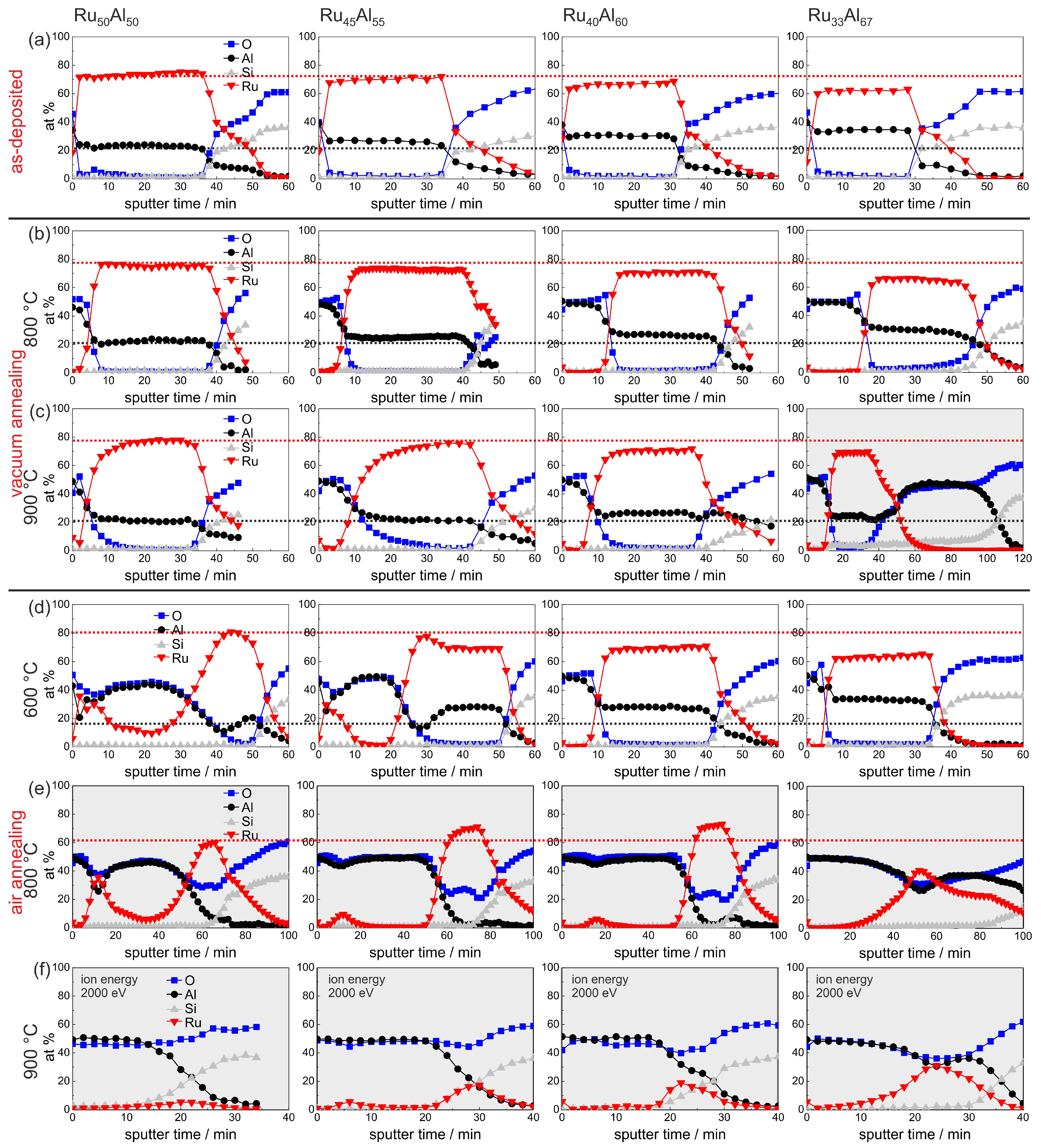
An overview summary of the results of the AES measurements of all samples with the different compositions and for the different annealing temperatures is presented in Figure 7. In Figure 7a–e, the red and the black dotted lines indicate the maximum Ru and Al content, respectively, in the reference RuAl sample, which simplifies the comparison between the films. This assembly of all measurements, depending on both the initial composition and the annealing temperature, allows a direct comparison of all samples.
Figure 7.
Overview summary of the AES measurements of the samples with the different compositions RuAl, RuAl, RuAl and RuAl (a) after preparation and after heat treatment for 10 h at (b) 800 C; (c) 900 C under high vacuum, as well as (d) 600 C; (e) 800 C; and (f) 900 C in air. The red (black) dotted lines mark the Ru (Al) content in the reference RuAl sample to visualize the difference to the other samples. The majority of the measurements is scaled for a sputtering time of 60 min, and the others are marked with the light gray background. Different sputtering conditions are remarked upon where they are applied.
The sample with the lowest Ru content RuAl shows some peculiarities compared to the other films. The AES measurement of the 900 C vacuum annealed sample (Figure 7c) reveals a strong reaction between the film and the substrate. The sputtering of the Ru-Al layer is followed by a more than 40 min sputtering of an AlO layer. However, the thickness of this layer is probably overestimated due to charging effects. A reaction between the film and the substrate after annealing at this temperature is also indicated by the cross section image (Figure 3b) where inhomogeneities between the Ru-Al layer and the substrate are visible. Moreover, after annealing at 900 C in air (Figure 7f), this sample contains the highest residual Ru content of all prepared samples in this series.
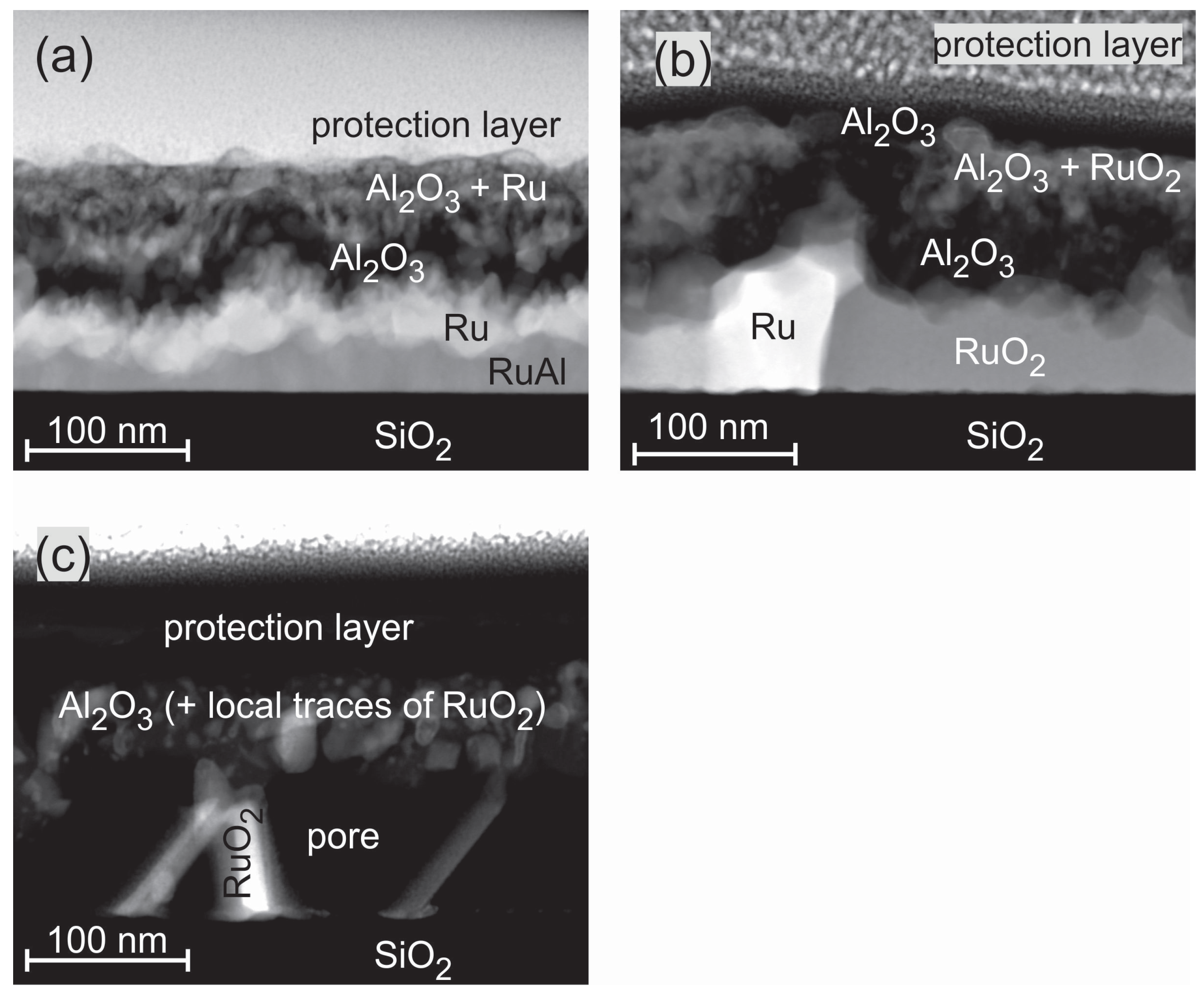
Figure 8 presents HAADF STEM images of the exemplary RuAl samples for the annealing steps under air conditions. The images confirm the complicated film structure that was derived from the cross section SEM images and AES measurements. After annealing at 600 C, the STEM images show a four-layer structure (Figure 8a). Above the SiO substrate, a thin Ru-Al layer with varying thickness (≈10–50 nm) is present, followed by a layer consisting of pure Ru (≈40 nm). On top of it, there is a layer of pure AlO (≈30 nm) followed by a matrix of AlO with embedded Ru grains (≈20–50 nm). An Ru rich layer directly below the sample surface as indicated by the AES measurements was not confirmed in the particular position of the STEM measurement.
Figure 8.
High-angle annular dark field scanning transmission electron microscopy (HAADF STEM) image (chemical contrast) of the RuAl sample annealed at (a) 600 C; (b) 800 C; and (c) 900 C for 10 h under air conditions.
The annealing at 800 C (Figure 8b) under air conditions leads to the partial oxidation of Ru. Above the substrate, a layer consisting of Ru grains embedded in a RuO matrix has formed (≈40–90 nm). Above this layer, a thicker AlO layer as compared to the 600 C case (≈60 nm) is present. For the 800 C sample, a thin layer (≈20 nm) with an accumulation of RuO grains within the AlO, which was detected by AES, is now clearly visible. The film is covered with a pure AlO layer.
During the annealing of the sample at 900 C in air (Figure 8c), a further oxidation of the RuO takes place. The formation of gaseous RuO species leads to the development of pores in the former Ru/RuO layer. The upper part of the film consists of AlO. The EDX analysis proves the presence of few Ru species at single regions in the AlO. This fits with the AES data, which only show a small amount of Ru (up to 5 at %) close to the interface of the SiO substrate. The wide transition zone in the AES measurement between the film and the SiO evolves from large pores that account for more than 50 % of the lower layer between the scattered RuO grains. This leads to a simultaneous sputtering of RuO and the SiO substrate.
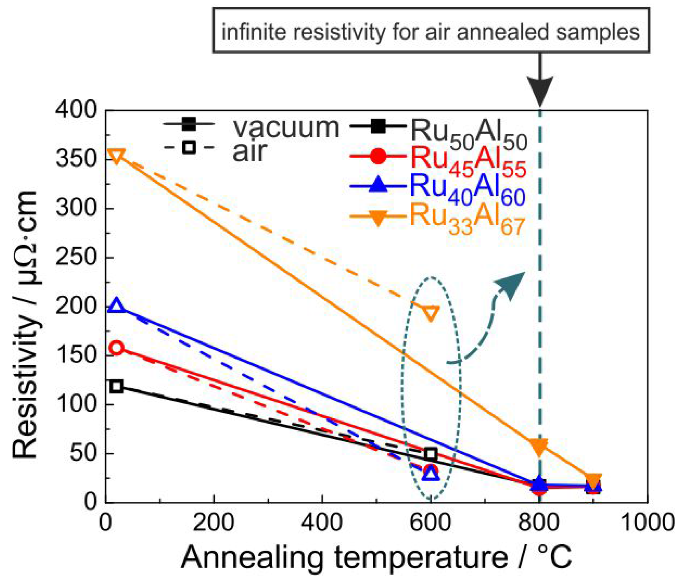
3.5. Electrical Properties
Since, for the application as metallization film, the electrical properties play an important role, the electrical resistivity was measured for the samples at RT after the annealing process. The results are presented in Figure 9. The resistivity was calculated from the sheet resistance considering the thickness of the films measured after deposition. Of course, due to the annealing process and the formation of the oxide layers, the real thickness of the conductive layer becomes smaller. The non-conductive oxides on top of the films and the formation of voids within the layers also complicate these measurements. Therefore, the results in Figure 9 represent only a mean value of the resistivity for the respective piece of sample.
Figure 9.
Electrical resistivity of the samples with the different compositions after annealing under high vacuum conditions (solid line) and air (dashed line); measured at RT. All films annealed in air at 800 C showed an infinite resistivity.
It is obvious that a higher Al content leads to a higher resistivity for the as-prepared samples. The XRD measurements showed a reduced crystallization with increased Al content, which can explain this trend of the electrical properties. The heat treatment under high vacuum conditions leads to a strong reduction of the resistivity. After annealing at 800 C, all samples except the RuAl film (60 cm) possess the same resistivity of about 17 cm. The heat treatment at 900 C hardly changes the resistivity of the RuAl, RuAl and RuAl samples. The value of RuAl further approaches the values of the other films and reaches 24 cm. The clear reduction in electrical resistivity is in agreement with the crystal growth, which is visible from the sharper peaks and higher intensity in XRD measurements as seen in Figure 1. A better crystallization of the RuAl B2 phase with higher temperature also leads to fewer defects. Both effects additionally reduce the electrical resistivity.
The situation is different if the samples are annealed under air conditions. The resistivity values for the 600 C annealed samples are also presented in Figure 9. However, the measurements showed no conductivity for the samples annealed at higher temperatures. The 600 C annealing leads to the lowest resistivity for the RuAl sample (28 cm), followed by the RuAl sample with a slightly higher value (32 cm) and the RuAl sample with a clearly higher resistivity (50 cm). Again, the highest value is observed for the RuAl film (195 cm). The same qualitative behavior is observed for the RuAl peak heights in the XRD measurements, proving that there is a clear coherence between higher XRD peaks and a lower electrical resistivity.
All films annealed in air at 800 C showed an infinite resistivity. As bulk RuO has a relatively low electrical resistivity of 35 cm [18], its formation does not explain why these samples are not electrically conductive anymore. Furthermore, FIB and STEM imaging of cross-sections showed a sparse distribution of pores well below the electrical percolation threshold.
Each electrical measurement was repeated four times and the direction of the electrical current was systematically changed, so that each measurement point consists of 16 individual measurements. The standard deviation of the measurements was in nearly all cases less than 0.1%, meaning that the respective error bar is smaller than the symbols shown in Figure 9. As mentioned above, the reduction of the effective thickness of the conductive layer is not considered in the calculation of the resistivity. Since the thickness of the conductive layer is smaller than the initial Ru-Al layer, the actual values of resistivity are smaller than the calculated ones.
4. Discussion
Several Ru-Al films with an intended Al content between 50 and 66 at % have been prepared and annealed at temperatures up to 900 C in air. However, different measurements revealed that the actual composition of the samples is shifted by 5 at % to the Ru-rich side. According to the Ru-Al phase diagram, there is an RuAl and RuAl phase [19]. Although the Al-rich RuAl and RuAl samples theoretically allow the formation of these phases, the XRD measurements only show RuAl reflexes in case of the RuAl film and an amorphous peak for RuAl.
There is some literature concerning oxidation processes in Ru-Al systems. Mainly, these investigations consider bulk materials, produced by arc-melting or induction melting [13,14,20,21], ingot or powder metallurgy [12] or thick films (600 nm [10,22]), and there is only one source dealing with relatively thin films (160–300 nm [11]). The authors distinguish the behavior of single-phase RuAl samples and those with additional Ru or Ru/RuAl eutectic phases because the oxidation resistance strongly depends on the morphology of the samples.
In general, it is stated that the presence of a second phase besides RuAl, namely Ru, is detrimental for the formation of a protecting AlO cover layer during annealing procedures. Bellina et al. state that Ru, which forms below the AlO cover, hinders a further diffusion of Al towards the film surface [13]. Oxygen diffuses faster inside the sample than Al outwards, leading to the formation of another AlO layer below the Ru rich layer [21]. For bulk materials, the authors describe the formation of a multilayer AlO/Ru or a porous AlO multiscale layer if the oxidation temperature is sufficient for the formation of RuO, and, subsequently, gaseous Ru oxides. The individual layer thicknesses of the AlO or Ru/RuO layers is larger than the total film thickness of the samples investigated in this study. Therefore, such multilayer systems are not observable in our films.
However, the formation of an AlO/Ru bilayer is clearly visible from the cross section images (Figure 3c) for the RuAl and RuAl films after annealing at 600 C in air. The wavy interface between the AlO and the Ru layer was similarly observed by Bellina et al. [13]. The AlO cover is not protecting for these films, leading to an oxidation of Ru to RuO during annealing at 800 C (Figure 1e). Already at this temperature, the cross section image shows cavities for the RuAl film that arise from a further oxidation of RuO to gaseous RuO or RuO. This effect also occurs for the RuAl film after annealing at 900 C.
Both films with higher Al content do not show a bilayer AlO/Ru structure after annealing at 600 C. It has to be assumed that these films contain sufficient Al to form an AlO cover layer at this temperature and to maintain enough Al within the film to maintain a RuAl phase and to prevent the formation of a Ru-rich phase. Therefore, the AlO cover is more protecting in these cases, which leads to a higher Ru content after annealing at 800 and 900 C in air. The lower the initial Ru content during deposition, the higher is the residual Ru content after the annealing (Figure 7f).
The growth rate of the AlO scale at the surface of the sample was determined by Soldera et al. for melted RuAl samples with initial RuAl composition. These samples contain an Ru or Ru/RuAl-eutectic phase between the RuAl grains. The authors derived a linear time dependence of the thickening with about 1.75 m/h [20]. On single phase RuAl bulk samples, a parabolic law for the growth of the oxide scale according to with k being about 0.043 m/h and a C of 0.47 m was concluded [14]. These growth rates were determined for an annealing at 1000 C in air and are much higher than the observed rates for the thin films investigated in this paper. Guitar et al. observed a higher oxidation resistance for thinner films (600 nm), since the higher density of grain boundaries facilitates a faster diffusion of Al to the surface [22]. This results in a faster formation of a dense AlO scale, which is likely also the case for our samples.
5. Conclusions
A sample series of Ru-Al films with increasing Al content was investigated concerning the influence of the Al content on the phase formation and film stability after heat treatment either under vacuum or under air conditions. Although a higher Al content in the as-deposited films leads to a more homogeneous microstructure as seen from cross section images and AES measurements, the RuAl phase formation is not supported during annealing under high vacuum conditions. However, the additional Al leads to more stable RuAl films under air annealing at 600 C and to a higher residual Ru or RuO content after heat treatment even at higher temperatures in air.
The measurements also reveal that a higher Al content leads to a thicker AlO cover layer after heat treatment, so that an estimation of the additional Al content, which is necessary for the RuAl phase formation during heat treatment, is hardly possible.
The results show that an excess of Al has a positive influence on the oxidation resistance but a negative effect on the RuAl phase formation. Therefore, a different approach has to be pursued to stabilize the RuAl phase in the Ru-Al films. Since the measurements also clearly prove that the AlO layer that forms during the heat treatment does not really act as a passivating layer, additional covering layers are necessary to protect the Ru-Al layer against the environment and to stabilize the RuAl phase.
Acknowledgments
The work was supported by German Federal Ministry of Education and Research under grant InnoProfile-Transfer 03IPT610Y. The authors gratefully acknowledge Erik Brachmann for film preparation, Thomas Wiek as well as Dina Bieberstein for FIB cuts and TEM lamella preparation, and Steffi Kaschube for AES measurements. Special thanks go to Volker Hoffman for GDOES measurements and to Horst Wendrock for EDX measurements for the calibration of the Ru-Al composition analysis.
Author Contributions
Marietta Seifert conceived and designed the experiments. Marietta Seifert performed the SEM, XRD and STEM measurements, mainly analyzed the data and wrote the paper. Gayatri K. Rane contributed to the analysis and evaluation of the data and to the discussion of the results. Steffen Oswald supervised the AES measurements and supported discussion of these data. Siegfried B. Menzel supported discussion and writing of the paper. Thomas Gemming supported STEM measurements and analysis as well as writing of the paper.
Conflicts of Interest
The authors declare no conflict of interest.
References
- Thiele, J.A.; Pereira da Cunha, M. Platinum and palladium high-temperature transducers on langasite. IEEE Trans. Ultrason. Ferroelectr. Freq. Control 2005, 52, 545–549. [Google Scholar] [CrossRef] [PubMed]
- Aubert, T.; Elmazira, O.; Assouar, B.; Bouvot, L.; Hehn, M.; Weber, S.; Oudich, M.; Geneve, D. Behavior of platinum/tantalum as interdigital transducers for SAW devices in high-temperature environments. IEEE Trans. Ultrason. Ferroelectr. Freq. Control 2011, 58, 603–610. [Google Scholar] [CrossRef] [PubMed]
- Aubert, T.; Bardong, J.; Elmazria, O.; Bruckner, G.; Assouar, B. Iridium interdigital transducers for high-temperature surface acoustic wave applications. IEEE Trans. Ultrason. Ferroelectr. Freq. Control 2012, 59, 194–197. [Google Scholar] [CrossRef] [PubMed]
- Taguett, A.; Aubert, T.; Lomello, M.; Legrani, O.; Elmazria, O.; Ghanbaja, J.; Talbi, A. Ir-Rh thin films as high-temperature electrodes for surface acoustic wave sensor applications. Sens. Actuators A 2016, 243, 35–42. [Google Scholar] [CrossRef]
- Mücklich, F.; Ilic, N. RuAl and its alloys. Part I. Structure, physical properties, microstructure and processing. Intermetallics 2005, 13, 5–21. [Google Scholar]
- Mücklich, F.; Ilic, N.; Woll, K. RuAl and its alloys, Part II: Mechanical properties, environmental resistance and applications. Intermetallics 2008, 16, 593–608. [Google Scholar] [CrossRef]
- Seifert, M.; Menzel, S.B.; Rane, G.K.; Hoffmann, M.; Gemming, T. RuAl thin films on high-temperature piezoelectric substrates. Mater. Res. Express 2015, 2, 085001. [Google Scholar] [CrossRef]
- Seifert, M.; Menzel, S.B.; Rane, G.K.; Gemming, T. The influence of barrier layers (SiO2, Al2O3,W) on the phase formation and stability of RuAl thin films on LGS and CTGS substrates for surface acoustic wave technology. J. Alloys Compd. 2016, 688, 228–240. [Google Scholar] [CrossRef]
- Seifert, M.; Menzel, S.B.; Rane, G.K.; Gemming, T. TEM studies on the changes of the composition in LGS and CTGS substrates covered with a RuAl metallization and on the phase formation within the RuAl film after heat treatment at 600 and 800 °C. J. Alloys Compd. 2016, 664, 510–517. [Google Scholar] [CrossRef]
- Guitar, M.A.; Ramos-Moore, E.; Mücklich, F. The influence of impurities on the formation of protective aluminium oxides on RuAl thin films. J. Alloys Compd. 2015, 594, 165–170. [Google Scholar] [CrossRef]
- Howell, J.A.; Mohney, S.E.; Muhlstein, C.L. Developing Ni-Al and Ru-Al intermetallic films for use in microelectromechanical systems. J. Vac. Sci. Technol. B 2011, 29, 042002-1–13. [Google Scholar] [CrossRef]
- Ilic, N.; Soldera, F.; Mücklich, F. Oxidation behavior of Ru(Al)-RuAl intermetallic eutectics produced by ingot and powder metallurgy. Intermetallics 2005, 13, 444–453. [Google Scholar] [CrossRef]
- Bellina, P.J.; Catanoiu, A.; Morales, F.M.; Rühle, M. Formation of discontinuous Al2O3 layers during high-temperature oxidation of RuAl alloys. J. Mater. Res. 2006, 21, 276–286. [Google Scholar] [CrossRef]
- Soldera, F.; Ilic, N.; Brännström, S.; Barrientos, I.; Gobran, H.; Mücklich, F. Formation of Al2O3 Scales on Single-Phase RuAl Produced by Reactive Sintering. Oxid. Met. 2003, 59, 529–542. [Google Scholar] [CrossRef]
- MultiPak, Software Package, version 9.6; ULVAC-PHI: Osaka, Japan, 2015.
- Pauw, L.J.v.d. A method of measuring the resistivity and Hall coefficient on lamellae of arbitrary shape. Philips Res. Rep. 1958, 13, 1–9. [Google Scholar]
- Oswald, S.; Seifert, M.; Menzel, S.; Gemming, T. AES and XPS Depth-Profiling of Ruthenium/Aluminum Films for High-Temperature Applications in SAW Metallizations, 19; Book of Abstracts P-Mo-16; Arbeitstagung Angewandte Oberflächenanalytik: Soest, Germany, 2016. [Google Scholar]
- Glassford, K.M.; Chelikowsky, J.R. Electron transport properties in RuO2 rutile. Phys. Rev. B Condens. Matter 1994, 49, 7107–7114. [Google Scholar] [CrossRef] [PubMed]
- Okamoto, H. Al-Ru (aluminum-ruthenium). J. Phase Equilib. 1997, 18, 105. [Google Scholar] [CrossRef]
- Soldera, F.; Iliv, N.; Manent Conesa, N.; Barrientos, I.; Mücklich, F. Influence of the microstructure on the formation of alumina scales on near stoichiometric RuAl produced by arc melting. Intermetallics 2005, 13, 101–107. [Google Scholar] [CrossRef]
- Cao, F.; Nandy, T.K.; Stobbe, D.; Pollock, T.M. Oxidation of ruthenium aluminide-based alloys: The role of microstructure and platinum additions. Intermetallics 2007, 15, 34–43. [Google Scholar] [CrossRef]
- Guitar, M.A.; Mücklich, F. Isothermal Oxidation Behaviour of Nanocrystalline RuAl Intermetallic Thin Films. Oxid. Met. 2013, 80, 423–436. [Google Scholar] [CrossRef]
© 2017 by the authors. Licensee MDPI, Basel, Switzerland. This article is an open access article distributed under the terms and conditions of the Creative Commons Attribution (CC BY) license ( http://creativecommons.org/licenses/by/4.0/).