Abstract
Liquid carbon dioxide-assisted (LCO2-assisted) atomization can be used in coal-water slurry gasification plants to prevent the agglomeration of coal particles. It is essential to understand the atomization behavior of the water-LCO2 mixture leaving the injector nozzle under various conditions, including the CO2 blending ratio, injection pressure, and chamber pressure. In this study, the flash-atomization behavior of a water-LCO2 mixture was evaluated with regard to the spray angle and penetration length during a throttling process. The injector nozzle was mounted downstream of a high-pressure spray-visualization system. Based on the results, the optimal condition for the effective transport of coal particles was proposed.
1. Introduction
Pressurized entrained flow gasification is a promising technology for the conversion of low-grade fuels to high-quality synthetic fuels, e.g., hydrogen and synthetic natural gas. High gasification efficiencies using liquid fuels or slurries can only be achieved through the generation of a fine homogenous spray at a high chamber pressure [1].
During coal-water slurry (CWS) gasification, there is a tendency for the coal particles to agglomerate within individual droplets while the water is evaporating; the agglomerates are then dried out and undergo thermal decomposition in the flame. The resulting coal-particle size distribution (p.s.d.) is determined to a greater degree by the size distribution of the atomized fuel spray than by the initial particle size of the coal. Large particles formed through agglomeration have increased burnout times and produce large fly ash particles [2]. A potential method for obtaining finer spray droplets is CO2-assisted atomization. The effect of disruptive or flash atomization in reducing the p.s.d. of droplets was evaluated. The CO2 is dissolved into the fuel by injection into the line between the pump and the fuel nozzle. During the pressure release in the atomizing nozzle, the dissolved CO2 changes to the gaseous phase and disrupts the coal-water mixture droplets.
Pure liquid CO2 (LCO2) has a different impact on the atomization at the injector nozzle when a LCO2 slurry is sprayed [3]. Compared with the conventional spray pattern of H2O, LCO2 produces effective breakup, leading to smaller liquid droplets, because of its lower viscosity and higher momentum flux. This helps to transport coal particles more uniformly inside the gasifier. This feature of better dispersion is attractive because it requires less heat release from partial combustion and thus less oxygen supply to the coal gasifiers. However, the effect of the blending ratio of LCO2 in the water on the atomization behavior has not been examined.
In a study on the spray formation of pure LCO2 [4], CO2 was expanded through a nozzle from a high pressure to an atmospheric pressure. The flash atomization and breakup mechanisms of LCO2 were examined using different liquid contents controlled by the degree of superheat. Under certain conditions, the LCO2 experienced a sudden pressure drop below the saturation pressure. LCO2 with different levels of superheat produced different behaviors of flashing sprays and snow-particle formation. Lee et al. found that sprays in flash-boiling conditions were atomized by bubble growth, resulting in a smaller droplet size than that generated by aerodynamic force alone [5]. Liu et al. used the laser-diffraction method to determine the p.s.d. of the spray [6].
Engelmeier et al. [7] used a pure carbon dioxide jet for cutting applications where carbon dioxide is compressed and expanded via a sapphire nozzle. A pressure chamber is installed downstream of the orifice to keep the post-expansion conditions above the triple-point pressure of carbon dioxide. They demonstrated that carbon dioxide has to be expanded to an environment of increased pressure and thus increase the liquid fraction to improve the impact of the jet.
Reverchon et al. reported that the solubilization of amount of supercritical CO2 in liquid solution could produce various powders with controllable size and distributions that are useful in several fine-particle production processes [8]. Supercritical dissolved-gas atomization is an atomization process in which carbon dioxide at a temperature and pressure above its critical point is used as the atomizing gas [9]. It relies on dissolved CO2 gas emerging from water to form bubbles. Therefore, this technique applies only to a limited range of liquids that can hold significant quantities of dissolved gas. As a result, the mean droplet diameter was mainly influenced by the sudden release of the CO2 gas dissolved in the water.
In general, the dissolved gas at the exit orifice nucleates to form gas bubbles, as in effervescent atomization, and can rapidly evaporate by flashing as well [10]. The result shows that the mean droplet diameter is mainly influenced by the sudden release of the gas dissolved in the liquid. However, the behavior of the water spray altered by the atomization of dissolved LCO2 was not experimentally evaluated in our previous work. That is, the spray characteristics of the water-LCO2 mixture must be studied.
In this study, the spray patterns of a water-LCO2 mixture were examined during a throttling process. The injector nozzle was mounted downstream of a high-pressure flashing-spray system, while the downstream pressure was controlled by a back-pressure regulator. A high-speed shadowgraph apparatus was used to evaluate the CO2-assisted atomization process.
2. Experimental Setup
Figure 1 presents a schematic of the high-pressure spray-visualization system used in this study. It consisted of an upstream chamber (vessel), a middle block, and a downstream chamber (vessel). There was an optical quartz window on the middle block and the two chambers, enabling the visualization of the flashing-spray behavior inside the nozzle and at the exit of the nozzle. The window was designed to withstand pressures up to 100 bar at a peak temperature of 80 °C, and a pressure-relief valve was installed to prevent pressure rises beyond this limit.
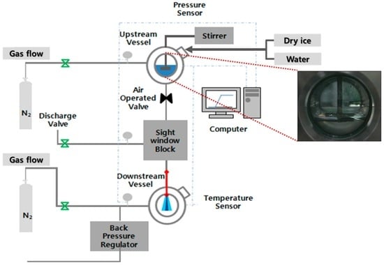
Figure 1.
Schematic of experimental setup.
A saturated mixture of CO2 was achieved by adjusting the temperature and mass of solid CO2 (SCO2). Different chamber temperatures were achieved with the use of a constant-temperature bath. As shown in Figure 1, the nozzle was installed between the middle block and the downstream chamber. It was 300 mm long with an internal diameter of 0.4 mm. Two different materials were used for the nozzles. Some were made of transparent Pyrex, enabling the visualization of the flow pattern inside the nozzle. This was useful for examining either capillary action or flash-boiling behavior. However, a copper nozzle was used for purposes other than internal visualization. A data-acquisition system was utilized to monitor the temperature and pressure inside the chambers, and a flow controller unit was used to turn the valves on and off pneumatically.
Water–LCO2 mixtures with different percentages LCO2 were prepared for blending. A water is first filled in upper chamber upto the desired volume, which is determined by water blending ratio on the basis of volume. Then, a solid CO2 is poured with desired volume percent. As a result, the CO2 in liquid and vapor phase is made with water as it reaches ambient temperature at equilibrium. Before the test, the mixture is agitated by stirring unit. Therefore, an efficient, continuous solubilization of CO2 in the liquid solution is allowed. The liquid CO2 exists as layer above the water layer, indicating low miscibility of CO2 with water. This separation is clearly observed in the inset of Figure 1. In addition, neither droplets nor particles of CO2 are found in the water. During this process, the total volume of the mixture remained constant. The effect of the blending ratio was investigated at two different pressures of the upstream and downstream chambers: 85/60 and 65/40 bar. Nitrogen gas was used as a filler when a pressure increase beyond the saturation pressure was necessary.
Figure 2 illustrates a schematic p-T diagram of the global multiphase behavior of carbon dioxide-water between 273 and 310 K as can be determined from the literature data [11,12]. In the figure, three-phase line connects all p, T coordinates where two liquid phases (a water-rich liquid L1 and a carbon dioxide-rich liquid L2) coexist with a carbon dioxide-rich vapor V. The pressure at L1L2V equilibrium is close to two-phase line, the liquid and vapor curve of pure CO2, but always below the vapor pressure of pure CO2. Because of this similarity of the three-phase line and two-phase line at tested ranges of pressure and temperature (25 °C), pressure release from 85 to 60 bar has higher presence of CO2-rich liquid(L2) than CO2-rich vapor(V) since it is located well over the three-phase equilibrium line. In contrast, pressure release from 65 to 40 bar experiences a phase transition from the CO2-rich liquid(L2) to the CO2-rich vapor(V) phase. The detailed properties of the two pure components, water and LCO2, are listed in Table 1.
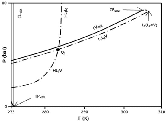
Figure 2.
Schematic of spray test condition mapping in P–T diagram of CO2-water mixture [12].

Table 1.
Properties of CO2 and water used in the experiment.
The constant pressure of the lower chamber was attained using a backpressure regulator mounted downstream of the lower chamber. Without the regulator, the pressure in the lower chamber would have increased as the liquid flow filled the lower chamber, thereby compressing the gas. The dimensions of the high-pressure flashing-spray system are listed in Table 2. The visualization region in the lower chamber was provided by an optical window with a diameter of 5 cm. It was desirable to fit most of the spray penetration into this visualization region for all the pressure conditions tested in this study. Thus, wetting of the chamber bottom by spray plumes should be prevented. For this reason, we selected a nozzle with a relatively high ratio of length to diameter, as previously mentioned.
Table 2.
Dimensions of high-pressure flashing-spray system.
A shadowgraph technique was employed to examine the flashing-spray patterns of the LCO2 and its mixture with water. During the throttling process across the nozzle, a high-speed camera was used to record consecutive images at a frame rate of 1/40,000 frames per second. Meanwhile, the pressure difference was measured to verify the downstream pressure controlled by the back-pressure regulator.
3. Results and Discussion
3.1. Effect of Water-Blending Ratio in Water-LCO2 Mixture
In a previous work [3], spray patterns under three different levels of upstream pressure (pressure difference) were observed using a high-speed camera: 65/40, 75/50, and 85/60 bar. At 65/40 bar, the internal flashing due to bubble formation caused a wider spray angle and shallower penetration length among three sprays. This is sometimes called a “bowl spray” and involves a high level of flash-atomization, which is an effective breakup mechanism of the liquid column, due to a burst of bubbles. A phenomenon similar to the bowl spray was observed with an increasing degree of superheat by Lin et al. [4] and Park et al. [13]. In contrast, a narrower spray angle and deeper penetration were observed at 85/60 bar, where the flash boiling is absent because of the liquid abundance. This is considered a normal jet spray. This difference is caused by the higher velocity of the liquid flow inside the nozzle orifice.
At the same pressure of 65/40 bar, the same nozzle length and diameter were used. The spray of H2O was not fully developed compared with that of LCO2. Such weak atomization is expected because of the low velocity and higher surface tension occurring when the H2O flows with a high viscosity inside the nozzle. This breakup mode is similar to the Rayleigh-type breakup mode observed in the experiment of Dechelette et al. [14], which is the main atomization zone of high-viscosity CWSs. However, the behavior of water sprays altered by the addition of LCO2 was not experimentally evaluated in our previous work.
Figure 3 shows the effect of the water fraction blended in the water-LCO2 mixture on the spray pattern at 65/40 bar. The amount of water in the mixture was increased while the total volume of the mixture was maintained. Water contents of 0 and 100 vol % correspond to pure LCO2 and pure water, respectively. The spray patterns under both conditions are similar to past observations, as previously mentioned. As the water content increased to 75%, the spray angle increased slightly, from 8.5° to 9.8° and then to 12.3°. Subsequently, it decreased to zero when the water content reached 100%. This was because of the increased dissolution of LCO2 when water content in the mixture is high. The high content of dissolved CO2 can evolve gaseous CO2 and thereby create the flash or disruptive boiling during a pressure release.
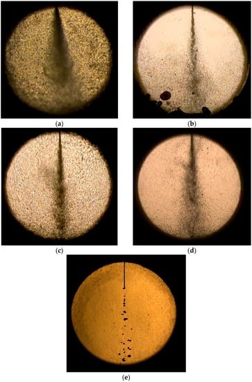
Figure 3.
Effect of water fraction blended in water-LCO2 mixture on spray pattern at 65/40 bar: (a) 0%; (b) 5%; (c) 25%; (d) 75%; and (e) 100% of water fraction.
A similar trend was observed when dissolved CO2 content increased in the water-CO2 mixture [2]. Better atomization was achieved by the increased flash boiling of CO2 dissolved in the mixture. The solubility of CO2 in water was fixed once pressure and temperature are given in the data. For example, 2.5 mol % is obtained for constant solubility at 65 bar and 25 °C in the predicted results of Larryn W. Diamond et al. [11]. When water makes up 75% of the mixture, absolute amounts soluble in the water become higher compared to the case of 25% despite having the same solubility. Therefore, higher soluble CO2 amount contribute to higher flash spray as water content increases in the mixture. However, this trend is not consistent with the results of supercritical dissolved-gas atomization [9]. The cone half-angle was reported for a wide range of gas-to-liquid ratios (GLRs). The cone half angle is approximately 13° at a low GLR and decreases to 4° when the GLR is increased. This is attributed to differences in the experimental apparatus and method.
Figure 4 and Figure 5 show the change in the spray angle and penetration length, respectively, according to the water fraction. The information was derived from the images of Figure 3. In the spray image, two lines are drawn and intersected at the nozzle tip. The angle between two lines is carefully measured for spray angle. We identified horizontal line of spray tip normal to vertical line and measured distance from nozzle tip to this line. This is used for penetration length. The data at a water content of zero are excluded in these plots. As the water content increased, the spray angle and penetration length increased to 75 wt % and then decreased. At 75% water blend condition, higher penetration length and angle were observed, indicating a higher degree of flash spray. In the case of higher flash spray, droplet size becomes smaller and more uniform. Therefore, droplet evaporates quickly and particle would agglomerate less. Based on this observation, a water content of 75 wt % appears to be optimal for the effective transport of coal particles by improving the spray quality.
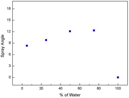
Figure 4.
Change in spray angle with respect to water fraction at 65/40 bar.
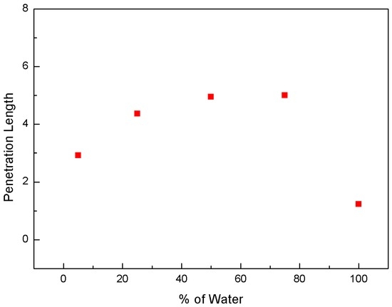
Figure 5.
Change in penetration length with respect to water fraction at 65/40 bar.
3.2. Effect of Injection Pressure
The spray characteristics were observed for a higher injection pressure of 85/60 bar. Figure 6 shows the effect of the water-blending ratio of the water-CO2 mixture on the spray angle at 85/60 bar. The variation of the spray angle with respect to the water fraction as the water content increased was similar to that at 65/40 bar. However, the angle was 15°–21°, which is far larger than that at 65/40 bar. This can be explained by the reduced evolution of gaseous CO2 in the water droplet. Dissolved CO2 has a higher pressure than vapor pressure at the temperature of 25 °C and is likely to remain a liquid. Therefore, the addition of liquid CO2 provides less viscosity for the mixture than for water, where the velocity and thus the momentum increase. This can increase the spray angle despite the lower amount of flash boiling. The presence of liquid in the jet was also important for the use of carbon dioxide in cutting applications [7]. While jets containing only gas and liquid showed almost no effect on the selected samples, the impact increased dramatically with the presence of liquid.
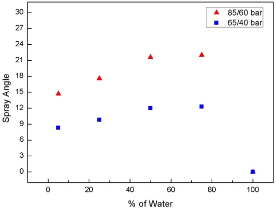
Figure 6.
Effect of water-blending ratio in water-CO2 mixture on spray angle at 85/60 bar.
The images in Figure 7 compare the effects of the water fraction and the injection pressure on the spray pattern of the water-CO2 mixture. They confirm that the spray angle increases with the injection pressure and has little dependence on the water-blending ratio. Compared with the 65/40-bar condition, less flash boiling was apparent at 85/60 bar.
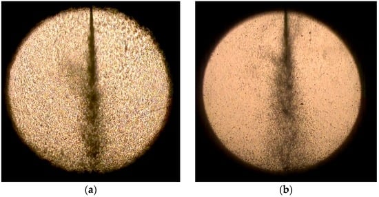
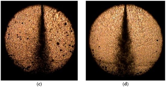
Figure 7.
Comparison of effects of water fraction and injection pressure on spray pattern of water-CO2 mixture: (a) 25% at 65/40 bar; (b) 75% at 65/40 bar; (c) 25% at 85/60 bar; and (d) 75% at 85/60 bar.
Figure 8 shows the dependence of the distribution of the liquid-droplet size on the degree of flash boiling. A conventional image-analysis technique was employed to obtain the droplet-size distribution. The results show that the mean diameter of the liquid spray at 65/40 bar was 150 μm. However, the higher pressure of 85/60 bar yielded a larger droplet of 300 μm with a larger deviation from the mean diameter. A similar trend in the droplet-size distribution was observed by Xiao et al. [15], who demonstrated that the addition of CO2 in diesel spray produced a far more uniform droplet size because of the flash separation of CO2 from the liquid. The finer and more uniform droplet confirms the strong flash atomization of the spray at 65/40 bar. This condition is favorable, as small liquid droplets may evaporate quickly and thereby prevent coal agglomeration when coal is present [2]. The size distribution was measured using the open source software ImageJ. The threshold was appropriately chosen to identify the droplet particle from the background. Then, a measuring tool was used to calculate the size of multiple droplets automatically. It is instructive to note the limitations of the shadowgraph technique. Smaller droplets scatter away much less light than large droplets. Therefore, the smallest droplets in the spray are not detectable with current shadowgraph technique. However, this effect may not be significant when determining any difference in injection pressure since it is present at both pressure conditions.
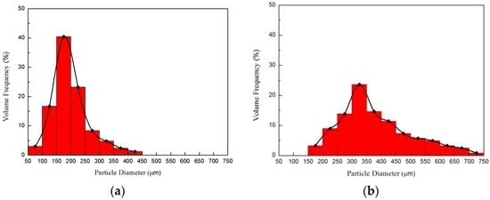
Figure 8.
Dependence of atomized liquid droplet distribution on degree of flash boiling at (a) 65/40 and (b) 85/60 bar.
3.3. Effect of Chamber Pressure
Figure 9 shows a series of spray events of LCO2-water mixture at different chamber pressures. As the chamber pressure increased at the same injection pressure, the flow rate decreased, which reduced the spray angle as well as the penetration length. This phenomenon was observed in the visualization results of Jakobs et al. [1] and Johnson et al. [16]. The spray angle as a function of the chamber pressure has been measured for values between 1 and 20 bar [1]. An increase in the chamber pressure from 1 to 20 bar results in a decrease in the water-spray angle from 36° to 24°. An increased chamber pressure appeared to contract the spray, yielding a more dense cloud of droplets compared with the corresponding atmospheric case. This was explained by the smaller volume of the entrained air due to the increased pressure. This tendency matches the diesel spray reported in [17].
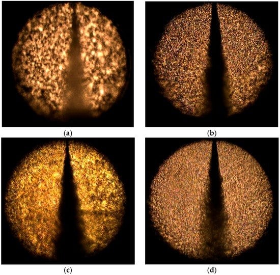
Figure 9.
Series of spray events of LCO2-water mixture reported at different chamber pressures with same injection pressure (75 bar): (a) 70 bar; (b) 60 bar; (c) 50 bar; and (d) 30 bar.
Figure 10 shows the temporal variation of two different pressures between the chambers during the throttling process. One is the upstream pressure (injection pressure), and the other is the downstream pressure (chamber pressure). The chamber pressure remained constant, indicating the proper operation of the back-pressure regulator. The injection pressure in the upper chamber experienced a continuous and smooth decay during the throttling process.
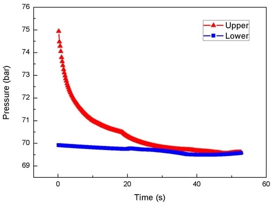
Figure 10.
Temporal variation of differential pressure between chambers during the throttling process at 75/70 bar.
Figure 11 plots the spray angle against the pressure difference. When the chamber pressure is high, the pressure difference is low, which indicates a reduced flow rate. The spray angle remains low at 13.5°. However, when the chamber pressure decreases, i.e., the pressure difference increases, the angle is increased to 20° and afterwards it is not changed substantially. The latter is attributed to choke flow, where vapor is prevalent in the mixture and therefore the flow rate is limited.
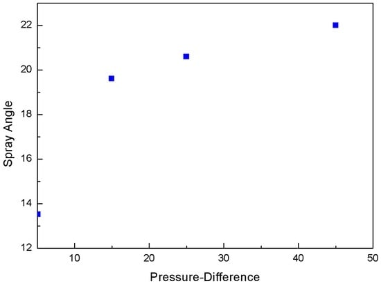
Figure 11.
Variation of spray angle with respect to pressure difference.
4. Conclusions
We investigated the spray characteristics of a mixture of LCO2 and water leaving an injector nozzle. The optimal amount of CO2 in the mixture was reported for the spray angle and length. This value was determined by the difference in the solubility of CO2 in the water-LCO2 mixture. The smaller droplets obtained at 65/40 bar indicate the strong flash atomization of the spray compared with 85/60 bar. Changes in the chamber pressure have no significant influence on the spray angle, except in the case of a high chamber pressure.
Acknowledgments
The authors thank the Korean government (MKE) for financial support from the manpower program (No. 20144010200780). This work was supported by a National Research Foundation of Korea grant (NRF-2016M1A3A1A02005033) funded by the Korean government (MEST).
Author Contributions
Hakduck Kim and Changyeon Kim performed the spray experiment under the advice of Juhun Song. Heechang Lim reviewed the experimental data and revised a manuscript. Juhun Song supervised the research and wrote the manuscript.
Conflicts of Interest
The authors declare no conflict of interest.
References
- Jakobs, T.; Djordjevic, N.; Fleck, S.; Mancini, M.; Weber, R.; Kolb, T. Gasification of high viscous slurry R&D on atomization and numerical simulation. Appl. Energy 2012, 93, 449–456. [Google Scholar]
- Yu, T.U.; Kang, S.W.; Beer, J.M.; Teare, J.D.; Sarofim, A.F. Fundamental Aspects of coal-Water Fuel Droplet Combustion and Secondary Atomization of Coal-Water Mixtures, Final Report; Cambridge: London, UK, 1987; Volume II. [Google Scholar]
- Kim, K.W.; Kim, H.D.; Kim, C.Y.; Song, J.H. Flash spray characteristics of a coal-liquid carbon dioxide slurry. Korean J. Chem. Eng. 2016, 33, 1612–1619. [Google Scholar] [CrossRef]
- Lin, T.C.; Shen, Y.J.; Wang, M.R. Effects of superheat on characteristics of flashing spray and snow particles produced by expanding liquid carbon dioxide. J. Aerosol Sci. 2013, 61, 27–35. [Google Scholar] [CrossRef]
- Zeng, Y.; Lee, C.F.F. An atomization model for flash boiling sprays. Combust. Sci. Technol. 2001, 169, 45. [Google Scholar] [CrossRef]
- Liu, Y.H.; Calvert, G.; Hare, C.; Ghadiri, M.; Matsusaka, S. Size measurement of dry ice particles produced from liquid carbon dioxide. J. Aerosol Sci. 2012, 48, 1. [Google Scholar] [CrossRef]
- Engelmeier, L.; Pollak, S.; Kilzer, A.; Weidner, E. Liquid carbon dioxide jets for cutting applications. J. Supercrit. Fluids 2012, 69, 29–33. [Google Scholar] [CrossRef]
- Reverchon, E. Supercritical-Assisted atomization to produce micro- and/or nanoparticles of controlled size and distribution. Ind. Eng. Chem. Res. 2002, 41, 2405–2411. [Google Scholar] [CrossRef]
- Caputo, G.; Adami, R.; Reverchon, E. Analysis of dissolved-gas atomization: Supercritical CO2 dissolved in water. Ind. Eng. Chem. Res. 2010, 49, 9454–9461. [Google Scholar] [CrossRef]
- Sher, E.; Elata, C. Spray formation from pressure cans by flashing. Ind. Eng. Chem. Process Des. Dev. 1977, 16, 237–242. [Google Scholar] [CrossRef]
- Diamond, L.W.; Akinfiev, N.N. Solubility of CO2 in water from −1.5 to 100 °C and from 0.1 to 100 MPa: Evaluation of literature data and thermodynamic modeling. Fluid Phase Equilibria 2003, 208, 265–290. [Google Scholar] [CrossRef]
- Wendland, M.; Hasse, H.; Maurer, G. Experimental pressure-temperature data on three- and four-phase equilibria of fluid, hydrate, and ice phases in the system carbon dioxide-water. J. Chem. Eng. Data 1999, 44, 901–906. [Google Scholar] [CrossRef]
- Park, S.; Lee, S.Y. An experimental investigation of the flash atomization mechanism. At. Sprays 1994, 4, 159–179. [Google Scholar] [CrossRef]
- Dechelette, A.; Campanella, O.; Corvalan, C.; Sojka, P.E. An experimental investigation on the breakup of surfactant-laden non-Newtonian jets. Chem. Eng. Sci. 2011, 66, 6367–6374. [Google Scholar] [CrossRef]
- Xiao, J.; Qiao, X.; Huang, Z.; Fang, J. Study of droplet size and velocity of fuel containing CO2 spray by means of PDA. Chin. Sci. Bull. 2004, 49, 1195–1199. [Google Scholar] [CrossRef]
- Johnson, J.E.; Yoon, S.H.; Naber, J.D.; Lee, S.Y.; Hunter, G.; Truemner, R.; Harcombe, T. Characteristics of 3000 bar diesel spray injection under non-vaporizing and vaporizing conditions. In Proceedings of the 12th Triennial International Conference on Liquid Atomization and Spray Systems (ICLASS), Heidelberg, Germany, 2–6 September 2012.
- Risberg, M.; Marklund, M. Visualizations of gas-assisted atomization of black liquor and syrup/water mixtures at elevated ambient pressures. At. Sprays 2009, 19, 957–967. [Google Scholar] [CrossRef]
© 2016 by the authors; licensee MDPI, Basel, Switzerland. This article is an open access article distributed under the terms and conditions of the Creative Commons Attribution (CC-BY) license (http://creativecommons.org/licenses/by/4.0/).