1. Introduction
Reducing carbon emissions and enhancing the efficiency of clean energy utilization have become critical issues for global sustainable development as global climate change intensifies and fossil energy resources gradually deplete. As of 2024, 151 countries worldwide have set “carbon-neutral” goals and are accelerating energy structure optimization through various measures. For instance, the European Union, through the European Green Deal, has been promoting the large-scale development of wind and solar power while establishing the EU Emissions Trading System (EU ETS) to guide the transition of high-emission industries [
1]. The United States has set a target to achieve carbon-free electricity by 2035 and increase policy support for new energy technologies [
2]. China has proposed the construction of a new power system primarily based on renewable energy, promoted the large-scale application of wind and solar power generation, and established a unified national carbon trading market.
The penetration of renewable energy sources such as wind and solar power into the grid has significantly increased with the increase in environmental demands and rapid advancements in new energy technologies. Due to the volatility and intermittency of renewable methods, the instability of power generation has risen, making it difficult to maintain the balance between supply and demand, leading to frequent voltage fluctuations and frequency deviations in the grid, which could even trigger severe power outages [
3,
4]. In addition, responding to frequent frequency regulation tasks has placed increased operational pressure on traditional thermal power units, causing instability in combustion and unit pressure fluctuations, which severely affect their safety and stability [
5]. In this context, energy storage technology, as an important auxiliary frequency regulation tool, can effectively mitigate the impact of renewable energy volatility on the grid, improve grid stability and power quality, and enhance the operational safety of traditional thermal power units [
6,
7].
Battery energy storage systems have been widely used. For example, the Moss Landing Energy Storage Project, located in Monterey County, California, USA, has a total capacity of 750 MW/3000 MWh, making it one of the largest lithium-ion battery storage facilities in the world. However, in January 2025, a fire broke out at the Moss Landing storage facility. Previously, the project had also experienced overheating and small fire incidents in 2021 and 2022 [
8]. Their development potential is constrained by environmental pollution and safety issues. On the other hand, flywheel energy storage, as a power-type storage system, can compensate for these shortcomings and has become a potential candidate for long-term participation in the frequency response service market [
9,
10,
11,
12]. In Central China, a research team conducted performance tests on a 500 kW/100 kWh flywheel energy storage system. By integrating the system with automatic generation control (AGC) command data from a 300 MW thermal power unit, they designed a joint frequency regulation control strategy. The results showed that with the addition of the flywheel energy storage system, the frequency regulation compensation revenue increased by CNY 164.33 million, achieving an investment-output ratio of 4.56 [
13]. HESSs have emerged with the development of energy storage technologies, offering better frequency regulation performance and economic viability. A HESS typically consists of power-type and energy-type storage systems. Power-type storage offers advantages such as high cycle counts, fast charge/discharge rates, and large short-term charge/discharge power, while energy-type storage has high energy density and long charge/discharge durations. As shown in
Table 1 [
14,
15,
16], flywheel energy storage systems have lower energy density but have faster response and a longer cycle life, making them suitable for short-cycle, high-amplitude frequency fluctuations. In contrast, battery energy storage systems have higher energy density compared to flywheels but suffer from slower charge/discharge rates, lower cycle counts, and shorter lifespans, making them better suited for long-cycle, low-amplitude frequency fluctuations. The complementary advantages of these methods can be utilized through the combination of both types of storage in primary frequency regulation for thermal power units. This approach significantly improves the primary frequency regulation performance of the units. Additionally, mechanical energy storage methods such as pumped hydroelectricity, compressed air storage, and superconducting storage, despite exhibiting extremely long service lives, have relatively low energy densities and long response times, which are at a significant disadvantage compared to batteries and flywheels when applied to system frequency regulation. Moreover, the initial investment and construction costs are significantly increased [
17,
18].
In summary, an ICEEMDAN-based HESS power allocation method was first adopted in this study to determine the grid-connected power and the smoothing power required by the HESS. Secondary power allocation between the flywheel and the battery was achieved using low-pass filtering, with consideration of the impact of cutoff frequency on the allocation results. A lifecycle-based economic capacity configuration model for a HESS was established by incorporating the battery replacement frequency over its full lifecycle, and the optimal configuration was obtained using the particle swarm optimization (PSO) algorithm. Finally, based on actual data from wind–solar power stations, simulation analysis verified the effectiveness and economic efficiency of the flywheel–battery HESS in smoothing power fluctuations in integrated wind–PV power stations.
Therefore, the combination of flywheel and battery energy storage systems can fully leverage their respective advantages, effectively addressing issues such as frequency stability and economic feasibility. Many scholars, both domestically and internationally, have conducted research into frequency regulation control strategies and the economic models of HESSs composed of flywheels and batteries. A.J et al. [
19] proposed a HESS consisting of flywheels and batteries to meet the system’s frequency regulation needs while improving economic efficiency. Wang [
20] applied a HESS to wind power frequency regulation, using a dual-layer constrained optimization method to verify the effectiveness and economic viability of the model. Zou and Luo [
21,
22] integrated a multi-component HESS with thermal power units for primary and secondary frequency regulation, conducting profit calculations and technical–economic analyses to verify its feasibility and economic benefits. Guo [
23] also used a flywheel–lithium battery HESS for primary frequency regulation in solar power plants, proposing frequency allocation and adaptive cooperative control and establishing a primary frequency regulation model for PV plants with a frequency response layer. These studies show that HESSs composed of flywheels and batteries have significant development potential.
Virtual inertia and droop control are typical strategies for energy storage participation in primary frequency regulation. For example, Guo [
23] proposed adaptive varying-coefficient droop control for hybrid energy storage participating in primary frequency regulation in PV power plants. The results demonstrated that hybrid energy storage could effectively improve the primary frequency regulation performance of PV systems. The author [
24] analyzed the effects of virtual inertia and droop coefficients at different frequency regulation stages, showing that the power output of energy-type storage in hybrid energy systems is smaller, which helps extend the lifespan of energy storage components. Ma and Wu [
25,
26] combined positive and negative virtual inertia control with droop control. The simulation results showed that the dynamic performance of the system’s frequency was improved. However, the above studies did not investigate the proportion of virtual inertia output and droop output, leading to abrupt changes in energy storage output when switching between the two control modes and, therefore, failing to leverage the advantages of each control strategy fully. Wang and Li et al. [
27,
28] introduced weight factors for inertia control and droop control, which effectively alleviated over-charging and deep discharging issues in batteries. However, when the system frequency rate changes sign (i.e., switching between positive and negative virtual inertia outputs), only droop control is used, causing abrupt changes in energy storage output, which is unfavorable for the long-term use of energy storage systems.
In addition, substantial research on energy storage SOC control has been conducted globally [
29,
30,
31,
32] by utilizing fuzzy control or logistic functions to adjust SOC changes under frequency constraints and adopting SOC self-recovery strategies to enhance the service life and economic efficiency of energy storage. However, existing studies mainly focus on single energy storage systems, and SOC self-recovery strategies are mostly applied in the secondary frequency regulation stage [
33,
34,
35,
36] without considering the impact of SOC self-recovery for hybrid energy storage after primary frequency regulation and the resulting frequency deviation.
To address these issues, this paper proposes a primary frequency regulation control strategy for flywheel–battery hybrid energy storage based on fuzzy adaptive control and SOC self-recovery. The strategy uses fuzzy control to smooth the virtual inertia and droop output, reducing sudden changes in energy storage output when switching between control modes. Additionally, logistic functions are used to constrain the charging and discharging of the energy storage system, virtual inertia control, and droop control, ensuring rapid frequency regulation capability while preventing over-charging and deep discharging. Subsequently, after the primary frequency regulation is completed, the system enters the SOC self-recovery mode, introducing charging and discharging recovery coefficients for the flywheel and battery. This improves the SOC state of the energy storage while ensuring the grid frequency does not experience severe fluctuations. Finally, simulation examples are used to compare the proposed control strategy with existing strategies in the literature, validating the effectiveness of the proposed strategy in different frequency regulation scenarios.
2. Flywheel–Battery Hybrid Energy Storage Primary Frequency Regulation Frequency Response System Model
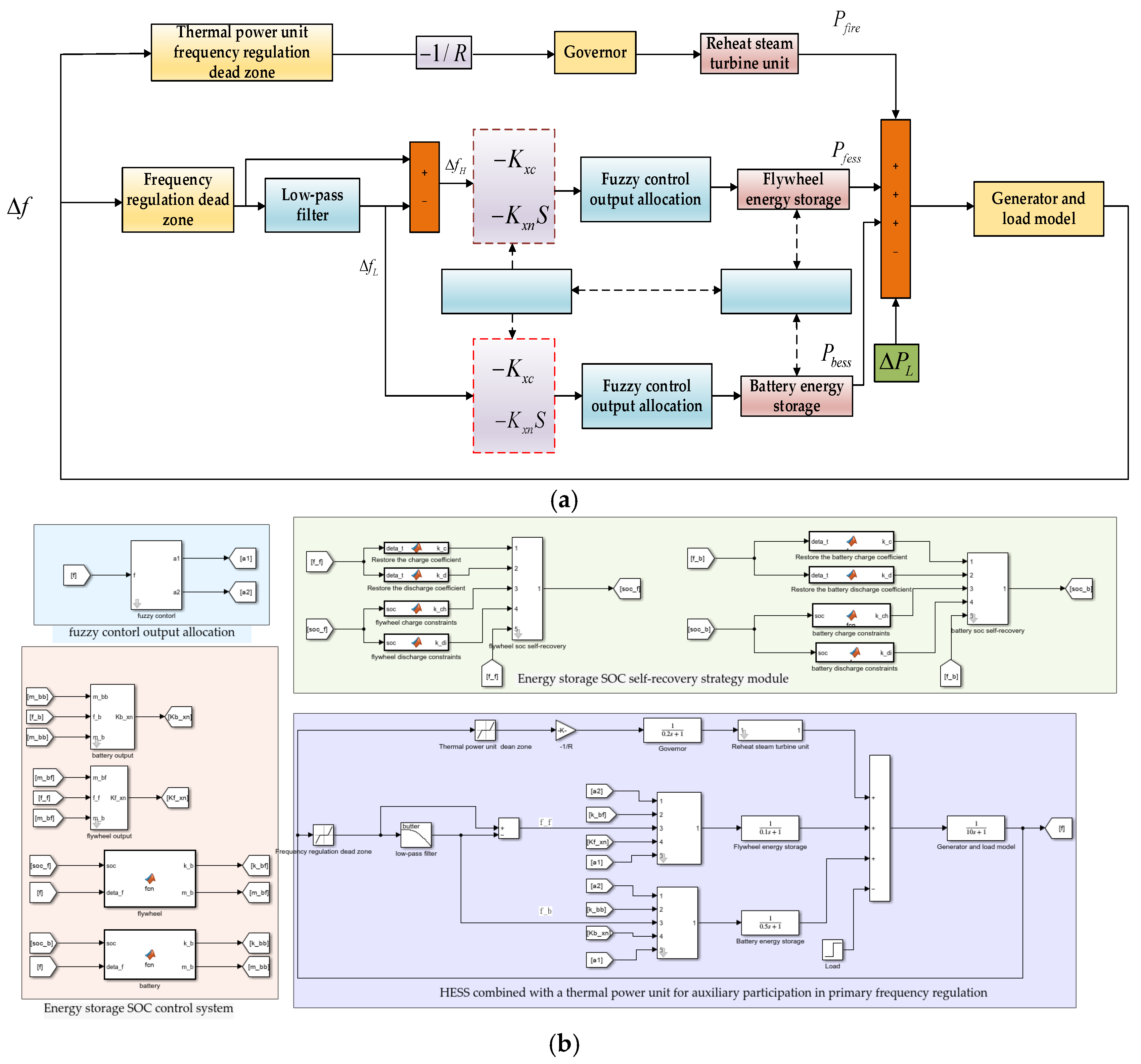
The overall system dynamic response model of the flywheel–battery hybrid energy storage system, which serves as the primary frequency regulation frequency response system model, is composed of several key components, as shown in
Figure 1: the traditional thermal power unit, HESS, the frequency deviation decomposition module, the fuzzy control module, the droop and inertia control module, and the SOC self-recovery module. In
Figure 1,
represents the system frequency deviation;
and
are the high-frequency deviation and low-frequency deviation, respectively; R is the droop coefficient of the traditional thermal power unit;
and
are the droop coefficient and the virtual inertia coefficient of the energy storage; and
,
, and
represent the power output of the thermal unit, flywheel, and battery, respectively.
A traditional thermal power unit typically consists of a governor and a reheat steam turbine. The transfer function of the steam turbine can be expressed as follows [
31]:
where
TCH, T
RH, and T
CO represent the time constants for the high-pressure, reheat, and low-pressure steam volume in a traditional thermal power unit, respectively.
FHP,
FIP, and
FLP are the power coefficients for the high-pressure, intermediate-pressure, and low-pressure cylinders, respectively.
The transfer function of the governor is typically represented as follows:
where
TG is the time constant of the governor.
The transfer function for the generator-load system is typically represented as follows:
where M is the rotor inertia of the generator, and D is the load-damping coefficient.
The HESS uses a high-precision first-order inertia model as the equivalent model, with the following transfer function:
where
TB and
TF represent the time constants of the battery energy storage and flywheel energy storage, respectively.
To fully leverage the advantages of hybrid energy storage, a first-order low-pass filter was employed in the frequency deviation decomposition module. After multiple tests, the time constant of the filter was determined to be 15.92, corresponding to a cutoff frequency of 0.01 Hz.
When the system experiences load disturbance (as shown in
Figure 1), frequency fluctuations occur. The HESS, combined with the conventional thermal power plant, performs primary frequency regulation if these fluctuations exceed the frequency control dead zones of the generator and energy storage. To maximize the rapid response and high precision of energy storage frequency regulation, the dead zone for energy storage is set to 60% of the traditional thermal power unit’s dead zone, with the aim of reducing the system frequency deviation. Once the system frequency signal passes through the thermal power unit’s dead zone, the output of the thermal power unit is determined by droop control. After the frequency signal passes through the energy storage dead zone, it undergoes processing via a low-pass filter. The low-frequency signals are assigned to the battery, while the high-frequency signals are assigned to the flywheel [
37]. After passing through their respective equivalent transfer function models and integrating with the traditional thermal power unit, the combined system acts on the system frequency through the generator-load transfer function, thereby completing the frequency regulation control.
3. Flywheel–Battery Hybrid Energy Storage Primary Frequency Regulation Control Strategy
Currently, the main control methods for energy storage frequency regulation are droop control and virtual inertia control. When the system frequency changes, droop control can effectively reduce the frequency deviation, positive virtual inertia control can effectively reduce the rate of frequency change, and negative virtual inertia control can accelerate frequency recovery. Wang Junyue and Li Junhui [
27,
28] applied droop control and positive and negative virtual inertia control over the entire frequency regulation period, using different weight coefficients to control the respective outputs during different frequency regulation stages, such as stages with mild frequency degradation, frequency degradation, and frequency recovery. The weight distribution strategy from Reference [
28] was adopted in this study as the control experiment group for traditional hybrid energy storage, with no energy storage and single-flywheel energy storage as the general experimental control groups.
The basic frequency regulation output allocation formula is as follows:
where
is the virtual inertia weight factor,
is the droop control weight factor,
is the energy storage output,
is the virtual inertia output, and
is the droop control output.
The stage of severe frequency deterioration is as follows:
The frequency recovery stage is as follows:
In Reference [
27], no negative virtual inertia output is applied during the frequency recovery period. Although Reference [
28] defines a negative virtual control output during the frequency recovery phase, the negative virtual output approaches zero in a very short time (0.001 s), and the output is solely governed by droop control. This results in a sudden change in the energy storage output when the frequency mode switches, reducing the lifespan of the energy storage system. Therefore, in this study, a fuzzy controller was employed, with the frequency deviation and its rate of change as inputs and the droop control and virtual inertia control proportional factors as outputs. This approach ensures a smooth transition between droop control and virtual inertia control, avoiding sudden jumps in the energy storage output.
3.1. Output Proportional Factor Design Based on Fuzzy Control
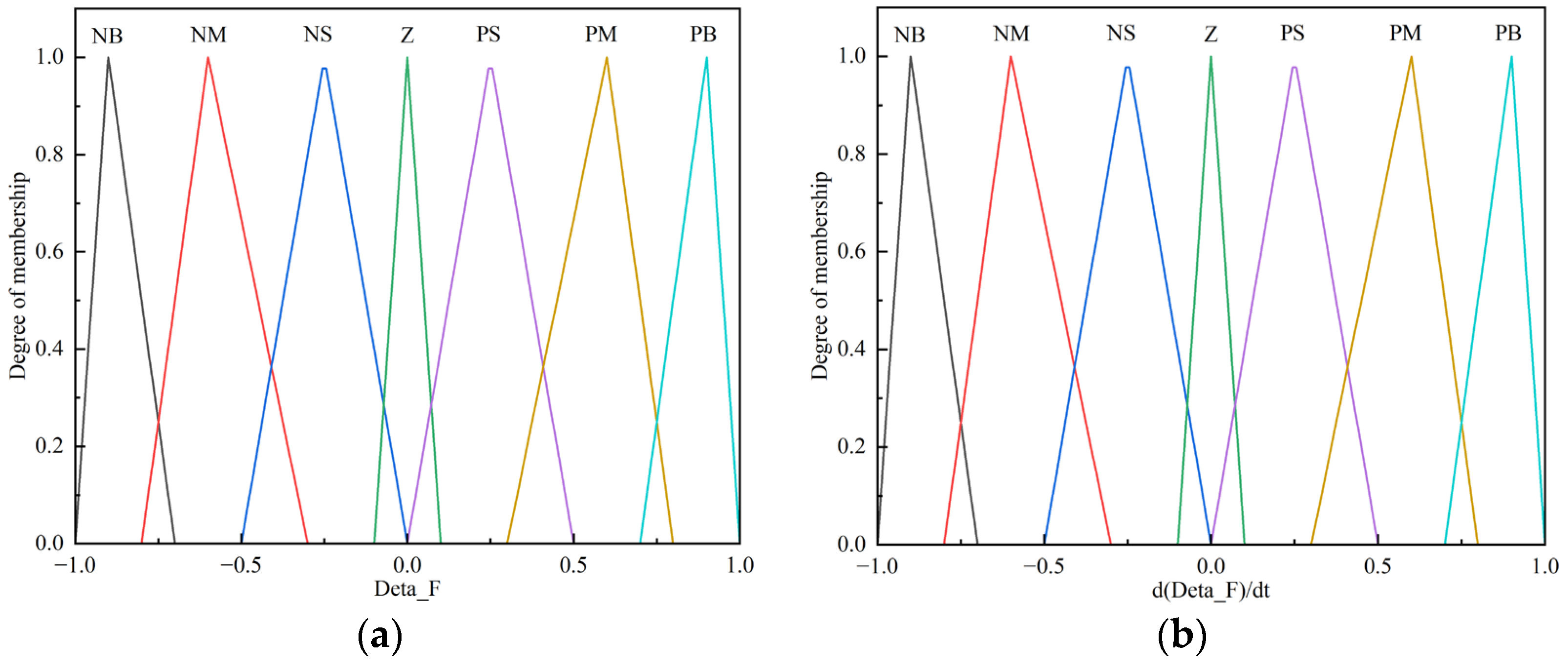
In fuzzy control, the frequency deviation and its rate of change are taken as input variables, normalized to per-unit values. The domain for these inputs is set to [−1, 1], and the fuzzy subsets are {NB (Negative Big), NM (Negative Medium), NS (Negative Small), ZE (Zero), PS (Positive Small), PM (Positive Medium), PB (Positive Big)}.
The virtual inertia control proportional factor is chosen as the output to ensure that the droop control output is the dominant factor, and the virtual inertia control output is secondary. The domain for the output is set to [0, 0.5], and the fuzzy subsets are {Z (Zero), S (Small), M (Medium), L (Large)}. The triangular membership function is employed as the membership function for the fuzzy control logic.
The membership functions of the input variables are shown in
Figure 2. A positive frequency deviation is represented by
> 0, indicating that the system frequency is higher than the nominal value, while a negative frequency deviation is represented by
< 0, indicating a frequency lower than the nominal value. As
increases, the system frequency deviation becomes larger, indicating more severe deterioration. Similarly,
represents the rate of change in the frequency deviation, where the sign indicates the direction of deterioration (positive for worsening and negative for improvement), and
represents the magnitude of the frequency deterioration speed.
The membership function for the rate of change in frequency deviation output is shown in
Figure 3. Here,
represents the virtual inertia output ratio factor, with four intervals defined as the output domain.
The fuzzy control logic rules are shown in
Table 2. When both
and
are in the NB (Negative Big) state, the frequency deviation and the rate of deterioration have reached their maximum values. In this case, a positive virtual inertia output is required to suppress the rate of frequency deterioration. When
is in the NB state and
is in the PB (Positive Big) state, although the frequency deviation is at its maximum, the rate of change in frequency is positive and relatively large. This suggests that the system is in the frequency recovery stage, with a rapid recovery rate. Therefore, the virtual inertia output can be reduced and set to Z (Zero) to minimize its impact. The fuzzy control rule table is generally symmetric. Based on the above control objectives and rules, the entire control system can be constructed.
To ensure that the output is as smooth as possible when the frequency regulation mode changes and to combine the advantages of both virtual inertia control and droop control, the virtual inertia proportional factor is increased during frequency deterioration to suppress the rate of frequency deviation and reduce the maximum frequency deviation. During the frequency recovery period, the droop proportional factor is increased, while the virtual inertia proportional factor is reduced, thus avoiding output jumps caused by droop control alone, while also reducing frequency fluctuations during this phase. Additionally, at every moment of frequency regulation, the droop output is prioritized, with virtual inertia output as a supplementary factor, effectively enhancing the system’s frequency regulation performance.
3.2. SOC-Based Frequency Regulation Output Control for Hybrid Energy Storage
It is necessary to impose constraints on the charging and discharging to fully leverage the respective advantages of the flywheel and battery and effectively utilize the regulation capability of the HESS.
The droop output and virtual inertia output formulas are as follows:
where
and
represent the droop coefficient and virtual inertia coefficient, respectively;
represents the frequency deviation; and
represents the rate of change in frequency deviation.
The droop coefficient is controlled by the SOC of the energy storage system, and the virtual inertia coefficient is controlled in proportion to the droop coefficient to regulate the respective frequency response outputs. The energy storage frequency response output is constrained using a logistic function, such that the droop output and virtual inertia output vary with the SOC of the energy storage. The design strategy proposed in this paper is as follows: the SOC of the flywheel and battery is divided into five ranges, in increasing order: Smin, Ssmall, S1, S2, Slarge, Smax, corresponding to the minimum, lower, slightly lower, slightly higher, and higher SOC values, respectively. Smax represents the maximum SOC values. When the frequency deviation exceeds the frequency regulation dead zone and is positive, the energy storage system is charged to absorb excess energy from the grid. Conversely, when the frequency deviation exceeds the frequency regulation dead zone and is negative, the energy storage system discharges to provide energy to the grid and prevent frequency decline.
The energy storage frequency regulation coefficients are given by the following formulas. Equations (12) and (13) describe the proportional control between droop output and virtual inertia output, while Formulas (14) and (15) represent the frequency regulation output coefficients constrained by the energy storage SOC.
where
is the maximum droop coefficient. A value of 15 is selected for
in this system to improve the system’s frequency regulation characteristics and prevent instability.
is the frequency regulation dead zone,
is the proportional factor, set to 0.5, and n is the parameter of the logistic function, which was set to 7 after multiple tests.
4. Flywheel–Battery Hybrid Energy Storage SOC Self-Recovery Strategy
After the HESS exits from the primary frequency regulation, to maintain the flywheel and battery SOCs at or near the ideal state, the system discharges and recharges the grid before the next frequency regulation. This helps to resolve the issue of insufficient frequency regulation output due to limited storage capacity. Therefore, the ideal state intervals in the previous SOC partition, s1 and s2, are defined as the target ranges. Outside these target ranges, the energy storage system implements a self-recovery strategy. However, the self-recovery process should also consider the impact on the grid frequency, and thus, the self-recovery charging and discharging coefficients are introduced while accounting for grid frequency deviation.
The smaller value of the self-charging and discharging coefficients based on SOC constraints is selected as the current self-recovery charging and discharging coefficient. The control flow is depicted in
Figure 4.
Using the SOC as the independent variable, the following charging and discharging coefficient constraint formula is established [
31]:
where
and
are the charging and discharging coefficients of the energy storage system constrained by its own SOC.
When performing SOC self-recovery, the charging and discharging of the energy storage system cause changes in the system’s frequency deviation. It is necessary to ensure that the grid frequency does not fall outside the frequency regulation dead zone during the recovery process to avoid affecting the normal operation of the energy storage system’s primary frequency regulation and to prevent the deterioration of grid frequency. Additionally, Reference [
23] explored the impact of energy storage dead zones on frequency regulation performance and verified that reducing the dead zone can improve the frequency stability of the grid. Therefore, in this study, the energy storage frequency regulation dead zone is set to 60% of the traditional thermal power unit’s dead zone. This effectively reduces the risk of frequency violations due to energy storage recovery while also minimizing the system’s maximum frequency deviation. The frequency deviation is divided into six levels: the minimum value
, the smaller value
, the slightly smaller value
, the slightly larger value
, the larger value
, and the maximum value
. In different frequency deviation ranges, the energy storage self-recovery charging and discharging coefficients are established as follows [
27]:
where
and
are the charging and discharging coefficients constrained by the system frequency.
The minimum value of the energy storage charging and discharging coefficient and the self-recovery coefficient are selected as the final energy storage recovery coefficient, which can be expressed as follows:
The energy storage self-recovery output is as follows:
where
is the energy storage self-recovery coefficient, and
is the energy storage recovery output.
5. Simulation Analysis
This paper establishes a HESS primary frequency regulation model based on MATLAB/Simulink R 2022b, with a system reference capacity of 600 MW and a rated frequency of 50 Hz. The primary frequency regulation deadband for the conventional thermal power unit is set to ±0.033, and the energy storage frequency regulation deadband is set to 60% of the unit’s deadband. The energy storage parameters are shown in
Table 3, while the parameters for the conventional thermal power unit and control strategy are shown in
Table 4. Since the method presented in this paper is an improvement upon traditional methods, the assumptions and parameters used are 600 MW and 50 Hz, with further details of the remaining parameters provided in
Table 3 and
Table 4.
5.1. Comparison of Different Strategies Under Step Load Disturbance Conditions
The initial SOC of the energy storage is set to 0.5, and a step load disturbance of 0.01 p.u. is applied. Simulation experiments were conducted for 30 s using the following strategies: no energy storage, single-flywheel energy storage, the traditional allocation method, and the method proposed in this paper. The frequency regulation performance indicators were compared using different strategies, such as maximum frequency deviation
, steady-state frequency deviation
, frequency deterioration rate
, and time of maximum frequency deviation
. In the case of the maximum dynamic power deviation
and the average output power
of the conventional unit, the smaller
and
are, the smaller the power fluctuations of the conventional unit, resulting in higher operational safety. The formulas for the output indicators of the conventional unit are as follows [
34]:
where
is the output power at the sampling point, N is the number of sampling points,
is the maximum output power, and
is the minimum output power.
Figure 5 shows the comparison of frequency deviations under step load disturbance conditions for different strategies. From the figure, it can be observed that the maximum frequency deviation with the proposed method is significantly smaller than the other methods, which validates the effectiveness of the proposed approach.
The comparison of frequency evaluation indicators under step load disturbance conditions for different strategies is shown in
Table 5. From the table, it can be concluded that with the proposed strategy, the maximum frequency deviation
is reduced by 48.05% compared to no energy storage, and the steady-state frequency deviation
is reduced by 24.38%. Compared to single-flywheel energy storage,
is reduced by 25.03% and
by 12.47%. Compared to the traditional method,
is reduced by 10.52% and
by 8.35%. The change rate
in the proposed method is reduced by 35.76% compared to no energy storage and by 13.59% compared to single-flywheel storage, being almost the same as the traditional method. Therefore, it can be concluded that the control strategy proposed in this paper effectively reduces both the maximum frequency deviation and the steady-state frequency deviation.
The comparison of thermal power output is shown in
Figure 6. From the figure, it can be seen that the thermal power output is significantly reduced when energy storage is configured. This proposed control method ensures that energy storage does not undergo abrupt changes when the frequency variation direction reverses. Instead, it smooths the output based on the fuzzy control strategy, preventing sudden power jumps.
The power output of the thermal power unit varies according to system frequency, which has already been illustrated in
Figure 5 under different strategies. Under the proposed control strategy, the HESS provides a smooth output, leading to a more stable system frequency variation. As a result, the power output of the thermal unit aligns with frequency changes, thereby avoiding the initial jump observed in the other three models.
The thermal power output indicators of different strategies are shown in
Figure 7. The maximum dynamic power deviations of the four control strategies are 0.0039 p.u.MW, 0.0054 p.u.MW, 0.0063 p.u.MW, and 0.0111 p.u.MW, respectively. The flywheel and the battery each share part of the output response when hybrid energy storage participates in frequency regulation. Compared with the no energy storage method, the proposed method reduces the maximum dynamic power deviation
by 51.25% and the average output power
by 63.21%. Furthermore, the proposed method reduces
by 14.28% and
by 30.43% compared to the traditional method by utilizing the advantages of both the flywheel and the battery in the HESS. As shown in the frequency indicators, the proposed method effectively reduces the maximum power deviation and average output of the thermal power plant while improving the system’s frequency regulation performance. It also enhances the safety and stability of the units, better ensuring the stability of the system’s frequency.
Figure 8 shows the flywheel energy storage output of different strategies. As a power-type energy storage method, the flywheel has a fast response and good ramp-up performance. From
Figure 8, it can be observed that when the system experiences a frequency step disturbance, the flywheel quickly responds with output and delivers high power. In traditional control strategies, the flywheel output is not smooth due to the changes in frequency rate of change and the switching mode of virtual inertia control, resulting in a peak output phenomenon. This can negatively impact the lifespan of the flywheel energy storage equipment. In contrast, the fuzzy control strategy used in this paper ensures smoother transitions when switching output modes, avoiding sudden output jumps. In the single-flywheel energy storage system, the flywheel participates in output frequency regulation throughout the adjustment period. In the HESS with battery storage, the flywheel output gradually decreases until it reaches zero and exits frequency regulation. This significantly reduces the configuration requirements for flywheel energy storage and lowers the overall cost of the HESS.
Figure 9 shows the frequency regulation output of the battery. Using the proposed control strategy, the frequency regulation deadband of the energy storage is reduced to 60% of the traditional deadband, improving the frequency regulation performance while also increasing the energy storage output. Additionally, compared with flywheel energy storage, battery energy storage, as an energy-type storage system, takes on the low-frequency components in frequency regulation. It is capable of stable and long-duration charging and discharging, which aligns with the performance requirements of battery storage.
5.2. Comparison of Different Strategies Under Random Continuous Load Disturbance Conditions
Actual frequency fluctuations are typically caused by random and continuous small-amplitude load variations. Therefore, a random continuous load disturbance of ±0.02 p.u. was introduced into the simulation model, with a simulation time of 1000 s. Meanwhile, under the SOC self-recovery strategy proposed in this study, the initial SOC of the flywheel was set to 0.7, and the initial SOC of the battery was set to 0.35 to verify the effectiveness of the self-recovery strategy when the flywheel and the battery in the hybrid energy storage system operate above or below the ideal SOC range.
The evaluation indicators for different strategies under continuous load disturbance conditions include the frequency peak-to-valley difference, frequency deviation RMS, and SOC deviation RMS. The peak-to-valley difference of energy storage output was introduced as an evaluation indicator to verify the energy storage output jump phenomenon of the proposed strategy. The smaller the value, the better the performance.
In the single energy storage strategy, the proposed control strategy for output jumps is not used, so only comparisons between the proposed method and the traditional method are considered. The calculation formulas are as follows [
33]:
where
represents the average output of the energy storage,
is the RMS value of the energy storage SOC,
is the SOC value at the sampling point, and
is the ideal SOC value, which is set to 0.5 in this work.
denotes the RMS value of the frequency deviation,
is the frequency deviation at the sampling point, and
represents the maximum dynamic frequency deviation of the energy storage. Additionally,
is the peak-to-valley difference of the frequency,
is the maximum frequency deviation, and
is the minimum frequency deviation.
The frequency deviation under random load disturbance conditions for different strategies is compared in
Figure 10. From the figure, it can be seen that the frequency deviation of the proposed method is lower than those of other methods.
Table 5 presents the comparison of frequency and output evaluation indices for different control strategies under random load disturbance conditions. It can be observed that using the proposed method,
decreases by 39.46% compared to the no-storage case, and
decreases by 46.03%. Compared to the single flywheel energy storage strategy,
decreases by 8.75%, and
decreases by 3.49%. Compared to the traditional method,
decreases by 7.34%, and
decreases by 6.74%.
The comparison of energy storage and thermal power output under random continuous load disturbance conditions is shown in
Figure 11, which describes the output of the thermal power, flywheel, and battery in the frequency regulation system under random continuous load.
Table 6 presents a comparison of system frequency and frequency regulation output evaluation indices for different control strategies under random load disturbance conditions.
In the proposed method, the average thermal power output is reduced by 56.64% compared to the no-storage scenario, by 1.90% compared to the single flywheel energy storage, and by 2.47% compared to the traditional method. Additionally, compared to the traditional method, the peak-to-valley difference in the flywheel and battery output is reduced. Flywheel energy storage, as a high-frequency power response system, reduces the peak-to-valley difference by approximately 47.97%, while battery energy storage, as a low-frequency power response system, reduces it by about 9.38%.
Therefore, the proposed method effectively reduces the RMS of frequency deviation and the peak-to-valley difference of frequency under random load disturbance conditions, decreases the average thermal power output, and mitigates the output jumps of energy storage to some extent.
To verify the effectiveness of the hybrid energy storage SOC self-recovery strategy, the initial SOC of the flywheel storage is set higher than the ideal SOC range (0.7), while the initial SOC of the battery storage is set lower than the ideal SOC range (0.35). The simulation results thoroughly validate the effectiveness of self-recovery charging and discharging of hybrid energy storage within different SOC ranges. The comparison curves of the SOC before and after the self-recovery strategy for both the flywheel and battery storage are shown in
Figure 12, and the corresponding evaluation indicators are listed in
Table 7.
From
Figure 12, it can be seen that using the proposed method, after energy storage exits frequency regulation, the SOC self-recovery process is triggered according to the control strategy. Since the initial SOC of the flywheel storage is higher, its SOC is adjusted downward to the ideal range. On the other hand, the initial SOC of the battery storage is lower, so its SOC is adjusted upward to reach the ideal range.
The comparison of SOC self-recovery evaluation indicators for hybrid energy storage is shown in
Table 7. Compared with energy storage systems without SOC self-recovery, the SOC RMS value for flywheel energy storage decreased by 8.79%, while the SOC RMS value for battery energy storage decreased by 16.68%. This demonstrates that the proposed strategy effectively helps the SOC of energy storage systems approach the ideal state, enabling more flexible frequency regulation output control in the next phase.
6. Conclusions
This paper proposes a primary frequency regulation control strategy for flywheel–battery hybrid energy storage based on fuzzy adaptive control and SOC self-recovery in response to the frequency fluctuations caused by wind and solar power integration into the grid. The strategy enables rapid frequency adjustment with varying system loads by applying fuzzy adaptive control to the energy storage frequency regulation output. Additionally, the SOC self-recovery strategy ensures that the SOC of the hybrid energy storage systems remains as close to the ideal range as possible, improving the frequency regulation performance. Simulation analysis was performed for the capacity of 600 MW, and the results demonstrate the following advantages of the proposed strategy:
- (1)
Under step load disturbance conditions, the maximum frequency deviation is reduced by 10.52%, and the steady-state frequency deviation is reduced by 8.35% compared to the traditional method. Under random load disturbance conditions, the RMS of frequency deviation decreases by 7.34%, and the frequency peak-to-valley difference decreases by 6.74% compared to the traditional method, effectively improving the system’s frequency regulation performance.
- (2)
To address the issue of output jumps in frequency regulation, fuzzy control is applied to smooth the output. Under random load disturbance conditions, compared with the traditional method, the maximum dynamic power deviation of flywheel energy storage is reduced by approximately 47.97%, and the maximum dynamic power deviation of the battery energy storage system is reduced by 9.38%. Meanwhile, the average output of thermal power generation decreases by 2.47%, which enhances the safety and stability of the hybrid energy storage frequency regulation system.
- (3)
The application of the hybrid energy storage SOC self-recovery strategy effectively restores or brings the SOC of the flywheel and battery closer to the ideal range. Compared with energy storage without SOC self-recovery, the SOC RMS of flywheel storage decreases by 8.79%, and the SOC RMS of battery storage decreases by 16.68%. This prevents the over-charging and over-discharging of the energy storage system and contributes to the subsequent frequency regulation performance, improving the overall performance of the HESS.
This study provides a theoretical foundation for energy storage participation in assisting thermal power frequency regulation and proposes a control strategy for multi-energy storage coupling in power system frequency regulation. Future research may explore various types of energy storage devices.
However, several potential challenges remain. For instance, the proposed control strategy is currently in the simulation stage and has not yet been tested in practical engineering applications. Additionally, the simulation experiments were conducted with a commonly adopted system capacity of 600 MW, and further investigation is needed to assess its applicability to different system capacities. Moreover, energy losses during transmission were not considered, nor were the economic impacts of renewable energy integration and the energy storage market.
In the next phase, we will conduct an in-depth study on energy losses, multi-capacity system configurations, and the optimal economic allocation of energy storage. Furthermore, engineering experiments will be carried out to validate the proposed strategy.


