Article

Experimental Methods and Equivalence Research on Inter-Turn Short Circuits in Power Transformers

1
School of Electrical Engineering, Xi’an Jiaotong University, Xi’an 710049, China
2
TBEA Electrical Equipment Group Co., Ltd., Tianjin 301700, China
3
TBEA Co., Ltd., Changji 831100, China
*
Author to whom correspondence should be addressed.
Energies 2025, 18(20), 5453; https://doi.org/10.3390/en18205453
Submission received: 23 September 2025 / Revised: 9 October 2025 / Accepted: 14 October 2025 / Published: 16 October 2025

Abstract

Inter-turn short-circuit faults in power transformers generate enormous short-circuit currents within the affected turns, making full-scale experimental investigations impractical. To address this issue, this study proposes an experimental method utilizing a third external short-circuit winding to simulate inter-turn faults through structural improvements in winding configuration and conductor current-carrying capacity. A simulation calculation model for transformer inter-turn short circuits was first established to investigate the equivalence between the proposed equivalent fault model and actual fault conditions under varying short-circuit positions and proportions. Simulation results demonstrate that both models exhibit consistent primary/secondary winding currents, short-circuit turn currents, and spatial radial leakage magnetic field distributions post-fault, with average errors less than 5%. Subsequently, an experimental platform for inter-turn short-circuit fault simulation was constructed. Current and leakage magnetic field measurements under different fault positions and proportions were validated against simulation data, confirming the proposed method’s equivalence. This approach provides an effective pathway for investigating fault characteristics and monitoring methodologies of transformer inter-turn short circuits.

1. Introduction

Power transformers are one of the critical electrical devices in power systems, undertaking the tasks of voltage conversion and energy transmission. Their safe and reliable operation is a key factor in ensuring power supply reliability [1,2,3]. The windings, serving as the primary conductive components of a transformer’s electrical circuit, play an indispensable role in its structural integrity. Any winding failure may directly compromise the transformer’s operational safety, potentially leading to catastrophic incidents such as explosions or fires, thereby incurring significant economic losses [4,5,6]. Statistical analyses indicate that interturn short-circuit faults account for 60–70% of all internal transformer failures [7,8,9]. These faults primarily arise from the cumulative effects of thermal and electrical stresses during long-term transformer operation, which degrade inter-turn insulation. Consequently, most inter-turn short-circuit faults occur under normal operating conditions [10]. During such faults, the minimal short-circuit impedance within the affected turns induces extremely high short-circuit currents. This phenomenon consequently generates substantial electrodynamic forces and thermal stresses due to Joule heating [11].
Studies [12,13,14] established simulation models of interturn short-circuit faults based on magnetic field-circuit coupling theory to investigate the variation characteristics of short-circuit currents in power transformers. Reference [15] developed a finite element simulation model in ANSYS to analyze the leakage flux distribution patterns during interturn short-circuit faults. Research [16,17] constructed a three-dimensional simulation model of a three-phase sectionalized winding transformer, systematically examining leakage flux distribution properties under various winding deformation and interturn short-circuit conditions. In works [18,19], a three-dimensional model of a 110 kV three-phase transformer was implemented to study leakage flux profiles during normal operation, different faulty winding configurations, and diverse interturn short-circuit locations. Reference [20] developed a computational model of a three-phase three-limb transformer to characterize the thermal evolution patterns and temperature distribution characteristics on both internal components and tank surfaces under normal and interturn fault conditions.
Reference [21] conducted interturn short-circuit fault simulation experiments on a three-phase transformer. To prevent transformer damage from excessive short-circuit currents while maintaining experimental controllability, the short-circuit current was constrained below the coil’s thermal limit during testing. In study [22], a dynamic simulation experimental system for interturn faults was constructed using a three-phase two-winding transformer. To mitigate transformer damage, a current-limiting resistor was series-connected within the short-circuit path, restricting the fault current to approximately 300 A. Research [23] established a three-phase experimental platform using three single-phase transformers. Similarly, the short-circuit current was regulated below three times the rated current to protect the transformer windings during experiments.
In summary, current research on transformer inter-turn short-circuits still exhibits notable limitations, primarily manifested in the following aspects:
1
Existing studies on transformer inter-turn short-circuits have been predominantly conducted through multi-physics coupling simulations using electromagnetic simulation software. During these simulations, the models are often established under idealized conditions, incorporating equivalent simplifications of actual transformer configurations. This inevitably introduces discrepancies between simulation results and practical scenarios.
2
In current full-scale prototype experiments, the substantial short-circuit currents circulating within the fault loops may cause irreversible damage to experimental transformers. Consequently, safety protocols typically require series-connected current-limiting resistors in short-circuit windings or voltage reduction to control fault current magnitudes. However, these modifications significantly deviate from actual inter-turn short-circuit operating conditions, thereby compromising the accurate characterization of transformer behaviors under such faults.
Therefore, developing a rationally equivalent experimental methodology for inter-turn short-circuit simulation holds critical significance for investigating fault mechanisms and characteristic signatures, and ultimately advancing effective monitoring techniques.
Addressing these challenges, this paper proposes a novel method simulating sudden inter-turn short-circuit faults under normal operating conditions through structural improvements in winding configurations and conductor load capacity, utilizing a peripheral third short-circuit winding. Based on a 0.4/0.4 kV-7 kVA single-phase dual-winding transformer, a transformer inter-turn short-circuit fault simulation model and a dynamic simulation experimental platform are established. The rationality of the inter-turn short-circuit equivalence method is investigated under the influence of factors such as the number and positions of short-circuited turns.

2. Simulation Method and Theoretical Derivation of Inter-Turn Short Circuit

2.1. Equivalent Method for Inter-Turn Short Circuit

Current experimental methods for interturn short-circuit faults primarily involve creating faults at different positions and proportions by tapping leads from various points on normal transformer windings. Although this method ensures the structural consistency between the experimental model and an actual inter-turn short-circuit fault, the short-circuited coil, as part of the original winding, cannot withstand the short-circuit current generated during the short-circuit fault. Therefore, current-limiting resistors must be connected in series at the tap points to restrict short-circuit currents within tolerable ranges. However, this significantly distorts the variation patterns and characteristics of key parameters during interturn faults. Moreover, repeated short-circuit experiments generate substantial heat that markedly accelerates insulation degradation in adjacent windings, causing irreversible damage to the test transformer. The difficulty in replacing or repairing post-fault windings further hinders repetitive experimental validation.
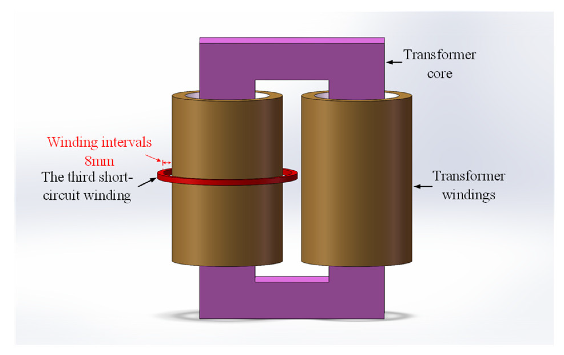
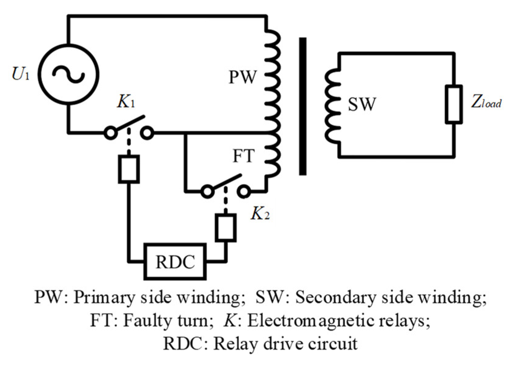
To address the aforementioned issues, this paper proposes an experimental method utilizing a third short-circuit winding to simulate interturn faults, as detailed in Figure 1.
In this method, improvements to the current-carrying capacity, thermal management conditions, and control strategies of the short-circuit winding effectively address the challenges of heat accumulation and insulation degradation. By implementing externally wound short-circuit turns around the transformer windings, conductors with higher current-carrying capacity can be selected while incorporating dedicated cooling measures. The external short-circuit turns also enable flexible adjustment of fault positions and proportions during simulation of interturn short-circuit conditions. Degraded insulation can be promptly replaced without compromising experimental continuity, significantly enhancing operational safety and test repeatability. Crucially, this approach eliminates insulation damage to the transformer’s primary windings.

2.2. Theoretical Calculation of Circuit Models

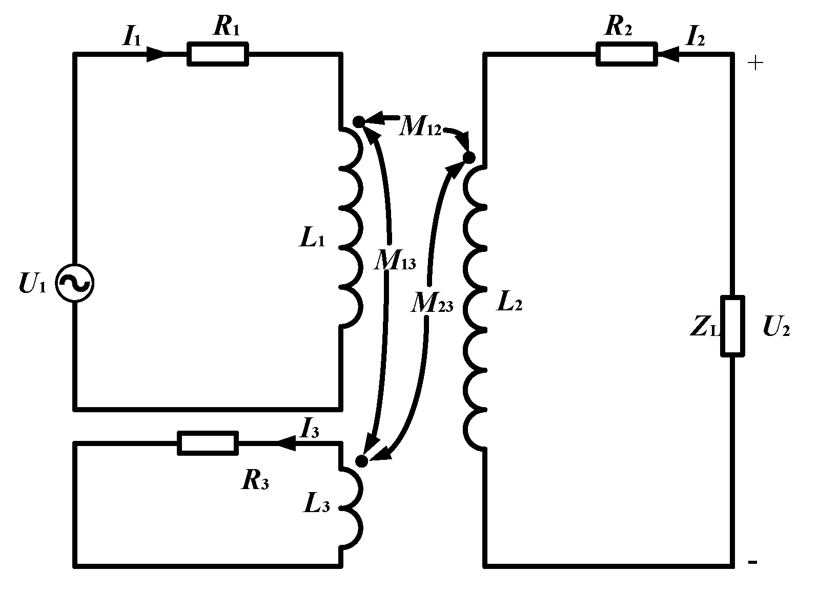
Taking a single-phase two-winding transformer as an example, when an interturn short-circuit fault occurs in the transformer windings, the structural configuration of the windings is altered, leading to corresponding changes in the resistance and inductance parameters of the transformer circuit. For interturn short-circuit faults in the primary winding, mutual coupling exists among the non-faulted portion of the primary winding, the short-circuited portion of the primary winding, and the secondary winding. The equivalent circuit diagram is illustrated in Figure 2.
In Figure 2, U1 and U2 denote the primary-side voltage and secondary-side voltage, respectively; ZL represents the load impedance on the secondary side; I1, I2, and I3 correspond to the current in the non-shorted portion of the primary winding, the secondary-side current, and the current in the shorted portion of the primary winding, respectively; L1, L2, and L3 are the self-inductances of the non-shorted portion of the primary winding, the secondary winding, and the shorted portion of the primary winding, respectively; M12, M13, and M23 represent the mutual inductances between the non-shorted portion of the primary winding and the secondary winding, between the non-shorted portion and the shorted portion of the primary winding, and between the shorted portion of the primary winding and the secondary winding, respectively; R1, R2, and R3 are the internal resistances of the non-shorted portion of the primary winding, the secondary winding, and the shorted portion of the primary winding, respectively.
Assuming the proportion of shorted turns to the total turns in the primary winding is x, the turns ratio between each portion is expressed as:
k 12 = ( 1 x ) N a N b k 13 = 1 x x k 23 = x N a N b
In Equation (1), Na and Nb represent the number of primary winding turns and secondary winding turns under normal operating conditions of the transformer, respectively; k12, k13, and k23 denote the turns ratios between the non-shorted portion of the primary winding and the secondary winding, between the non-shorted portion and the shorted portion of the primary winding, and between the shorted portion of the primary winding and the secondary winding, respectively.
According to the definition of resistance, the winding resistance in a transformer can be approximated as linearly proportional to the winding length. Consequently, the resistances of each winding portion after an interturn short-circuit fault are expressed as:
R 1 = ( 1 x ) R a R 2 = R b R 3 = x R a
In Equation (2), Ra and Rb represent the primary winding resistance and secondary winding resistance of the transformer under normal operating conditions, respectively; R1, R2, and R3 denote the resistance of the non-shorted portion of the primary winding, the secondary winding resistance, and the resistance of the shorted portion of the primary winding after the interturn short-circuit fault, respectively.
According to the equivalent principle, L a = L 1 + L 3 + 2 M 13 , where La is the self-inductance of the primary winding under normal operating conditions of the transformer. Additionally, the self-inductance of the transformer windings can be approximated as proportional to the square of the number of turns. Therefore, it follows that:
L 1 L 3 = ( 1 x x ) 2
The magnetic leakage coefficient of the transformer under normal working conditions is:
σ ab = 1 M ab 2 L a L b
Based on transformer theory, the self-inductances La and Lb of the primary and secondary windings, as well as the mutual inductance Mab, can be determined from the data obtained through transformer short-circuit and no-load tests, thus yielding the leakage magnetic coefficient under normal operation. When an interturn short-circuit fault occurs in the transformer, both its structural configuration and the distribution of leakage magnetic fields are altered, and the magnitude of leakage flux exhibits a certain relationship with the fault current magnitude. According to the structural characteristics of a single-phase two-winding transformer, the leakage magnetic coefficient under normal conditions can be adjusted as follows:
σ 13 = x ( 1 x ) 2 σ ab
Joint vertical 3–5 can be obtained:
L 1 = ( 1 x ) 2 L a 2 x ( 1 x ) ( 1 σ 12 1 ) + 1 L 3 = x 2 L a 2 x ( 1 x ) ( 1 σ 12 1 ) + 1 M 13 = x ( 1 x ) 1 σ 12 L a 2 x ( 1 x ) ( 1 σ 12 1 ) + 1
After an interturn short-circuit fault occurs in the transformer, both the shorted turns and the non-shorted turns are located on different core limbs from the secondary winding. Therefore, the mutual inductances M12 (between the non-shorted portion of the primary winding and the secondary winding) and M23 (between the shorted portion of the primary winding and the secondary winding) can be calculated using the approximate formula for mutual inductance, as shown in the following equation.
M 12 = N 1 N b R m M 23 = N 3 N b R m
In the equation: Rm is the magnetic reluctance of the transformer core’s magnetic circuit.
After determining the circuit parameters of each portion following the interturn short-circuit fault through known parameters, the loop voltage equations can be established for each portion [24], yielding:
U 1 = R 1 I 1 + L 1 d I 1 d t + M 12 d I 2 d t + M 13 d I 3 d t 0 = R 2 I 2 + M 12 d I 1 d t + L 2 d I 2 d t + M 23 d I 3 d t + Z L I 2 0 = R 3 I 3 + M 13 d I 1 d t + M 23 d I 2 d t + L 3 d I 3 d t
After listing the loop voltage equations for each portion following the interturn short-circuit fault, and utilizing the transformer parameter referral law to refer all parameters to the non-shorted portion of the primary side, it can be clearly observed through comparison that the two-winding transformer with an interturn short-circuit fault is equivalently represented as a three-winding transformer with an independent shorted winding. The equivalent circuit diagram is shown in Figure 3.
The meaning of each physical quantity in Figure 3 is the same as that of the physical quantity in Figure 1.

3. Winding Equivalence Simulation Model Verification

3.1. Simulation Model Establishment

This paper establishes a 1:1 inter-turn short-circuit simulation model for transformers based on a 0.4/0.4 kV-7 kVA single-phase dual-winding transformer, utilizing the electromagnetic simulation software MagNet developed by INFOLYTICA. By varying different factors influencing the spatial leakage magnetic field distribution after inter-turn short-circuit occurrences in transformers, the equivalence of simulating transformer short-circuit faults through an external third short-circuit winding is investigated. Within this software, unstructured tetrahedral meshes are employed for discretizing the simulation model. The electrical and physical parameters of the transformer are presented in Table 1.
To validate the inter-turn short-circuit equivalence method proposed in this paper, an actual inter-turn short-circuit fault model and a third short-circuit winding-based equivalent model were established. Both models adopted identical parameters except for the inter-turn short-circuit fault implementation methods. Detailed modeling was applied to the faulty winding, with each 1% segment decomposed into a single turn and uniformly wound from top to bottom. The transformer core was constructed by stacking multiple layers of 0.35 mm thick silicon steel sheets. Based on literature references and laboratory measurements, the short-circuit resistance at the fault point was set to 2.5 mΩ.
The following simplifications were implemented during modeling:
  • The current in transformer windings was assumed to be uniformly distributed, with each 1% axial segment equivalently represented as identical turns.
  • Winding manufacturing irregularities and coil arrangement variations were neglected, assuming uniform coil distribution throughout the winding.
  • External non-electromagnetic components such as transformer bases and clamps were excluded to reduce computational complexity while maintaining accuracy.
  • In subsequent simulation and experimental processes, the transient process of inter-turn short circuits in the transformer is ignored, and only the steady-state process formed after the inter-turn short circuit is considered.

3.2. Study on Equivalence-Influencing Factors

During normal transformer operation, the external third short-circuit winding remains disconnected from the main circuit, ensuring complete equivalence between both models. When inter-turn short-circuit faults occur, the number of shorted turns and fault location alter the leakage magnetic field distribution within the transformer, potentially affecting the equivalence of third-winding-based fault simulation. Consequently, simulation models were employed to investigate the impacts of these two factors on the equivalence of the proposed method.

3.2.1. Influence of Short-Circuit Position on Equivalence

Variations in inter-turn short-circuit positions differentially modify circuit configurations and parameters while directly determining post-fault leakage magnetic field patterns. A 1.5% inter-turn short-circuit ratio was simulated to evaluate positional effects on equivalence between third-winding simulation and actual faults. All parameters except fault location remained constant. Considering actual insulation thickness and winding encapsulation, an 8 mm gap was maintained between the third short-circuit winding and transformer windings, as shown in Figure 4. Short-circuit faults were subsequently induced at 15%, 50%, and 85% relative winding heights.
Variations in short-circuit positions affect the circuit configurations and parameters of transformers. The currents in the primary winding, secondary winding, and shorted turns of both the actual inter-turn short-circuit model and the third-winding-based simulated inter-turn short-circuit model under different short-circuit positions are listed in Table 2.
As can be observed from Table 2, the short-circuit fault currents at symmetrically central positions of the winding are identical, demonstrating a certain degree of symmetry. Meanwhile, as the short-circuit position approaches the mid-height of the winding, the short-circuit current slightly increases. This phenomenon is primarily attributed to the higher magnetic flux density within the core at the winding center, which induces a larger electromotive force in the short-circuit loop under identical conditions, thereby generating a greater short-circuit current. Across different inter-turn short-circuit positions, the currents in both the actual inter-turn short-circuit model and the equivalent inter-turn short-circuit model remain fundamentally consistent. The maximum deviation in primary winding current is 1.1%, while those for the secondary winding and shorted turns are 0.81% and 1.8%, respectively. Consequently, in terms of electrical effects, variations in inter-turn short-circuit positions exhibit negligible influence on the equivalence of the inter-turn short-circuit simulation method.
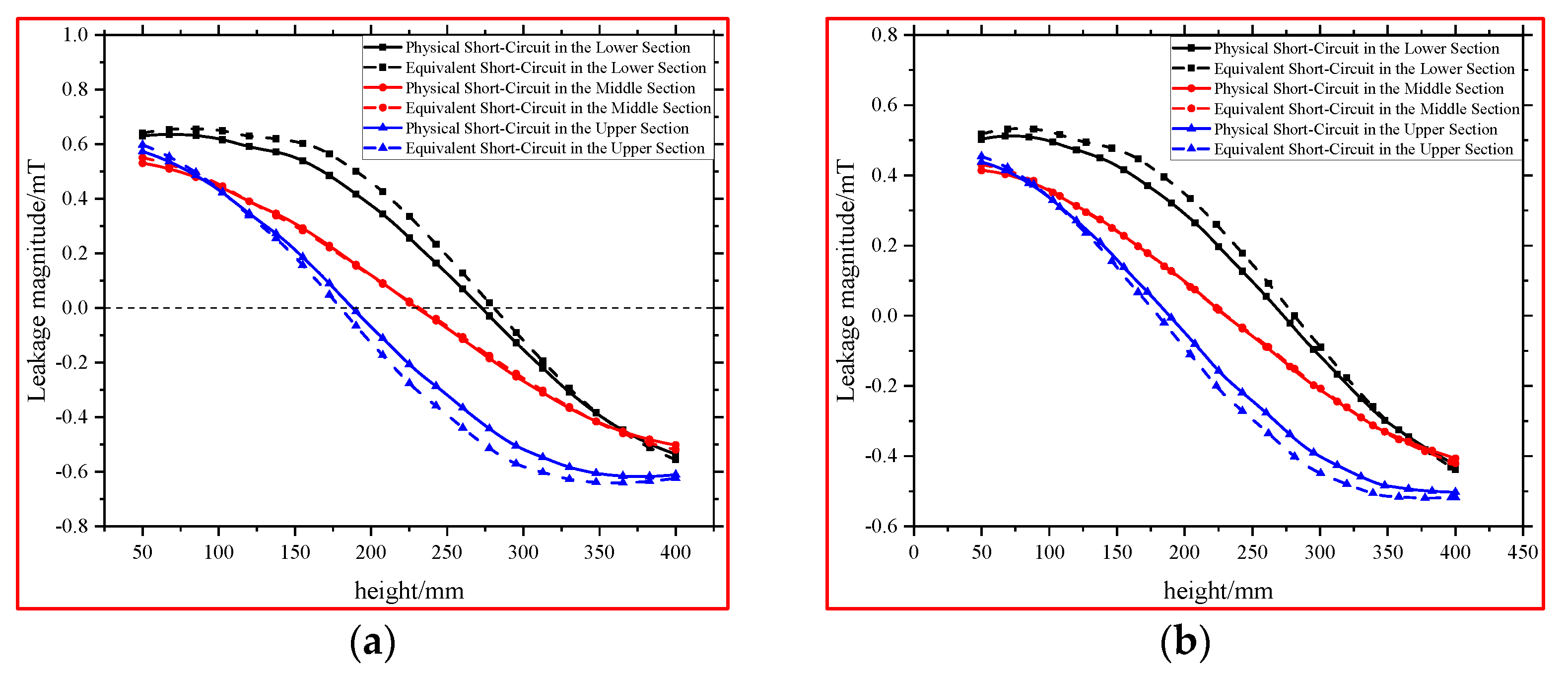
The simulated radial leakage magnetic field distributions of the actual inter-turn short-circuit model and the third-winding-based simulated inter-turn short-circuit model under different short-circuit positions are shown in Figure 5.
As can be observed from Figure 5, similar to the current, when an inter-turn short-circuit fault occurs symmetrically about the winding height, the fault-induced magnetic field also exhibits a certain degree of symmetry relative to the winding height. Additionally, since the leakage magnetic field caused by an inter-turn short-circuit at the winding center is symmetrically distributed about the mid-height, the overall leakage magnetic field retains symmetry during mid-height inter-turn short-circuit faults. When inter-turn short-circuit faults occur at different positions along the winding, the variation trends and general characteristics of the radial leakage magnetic field in both the actual inter-turn short-circuit model and the third-winding-based simulated inter-turn short-circuit model remain fundamentally consistent after fault initiation. Slight differences in magnetic field intensity at identical positions are observed, with analysis revealing an average discrepancy of less than 5% between the two models. Consequently, the location of the inter-turn short-circuit exerts negligible influence on the equivalence of the simulation method in terms of magnetic effects. Therefore, the inter-turn short-circuit simulation method proposed in this paper demonstrates equivalence to actual inter-turn short-circuit faults with respect to fault position.

3.2.2. Impact of Short-Circuit Proportion on Equivalence

The proportion of inter-turn short-circuit directly affects the magnitude of the electromotive force induced in the short-circuit loop, thereby significantly influencing the short-circuit current and the magnitude/distribution of the fault-induced leakage magnetic field. To investigate the impact of short-circuit proportion on the equivalence between the third-winding-based simulation method and actual inter-turn short-circuit faults, this study employs a case where an inter-turn short-circuit occurs at 15% relative winding height in simulations. While maintaining identical parameters except for the short-circuit turn ratio, and accounting for insulation thickness, the separation between the third short-circuit winding and the transformer winding is set to 8 mm. Short-circuit proportions of 1.5%, 3%, and 5% are simulated. The currents in the primary winding, secondary winding, and shorted turns of both the actual inter-turn short-circuit model and the third-winding-based simulated inter-turn short-circuit model under different short-circuit proportions are summarized in Table 3.
As shown in Table 3, with the increase in short-circuit turn proportion, the primary winding current rapidly rises to balance the additional magnetomotive force generated by the short-circuited turns. Concurrently, core saturation exacerbates the growth of the primary winding current. However, the short-circuited turn current initially increases and then slightly decreases because the induced electromotive force within the turns no longer increases linearly due to core saturation under elevated excitation currents, while the impedance of the short-circuited turns maintains a linear relationship with the short-circuit proportion. Furthermore, under different inter-turn short-circuit proportions, the currents in both the actual inter-turn short-circuit model and the equivalent inter-turn short-circuit model remain fundamentally consistent. The maximum discrepancies are 2.51% for the primary winding current, 2.5% for the secondary winding current, and 2.59% for the short-circuited turn current. Therefore, variations in the short-circuit proportion have negligible impact on the equivalence of the inter-turn short-circuit simulation method in terms of electrical effects.
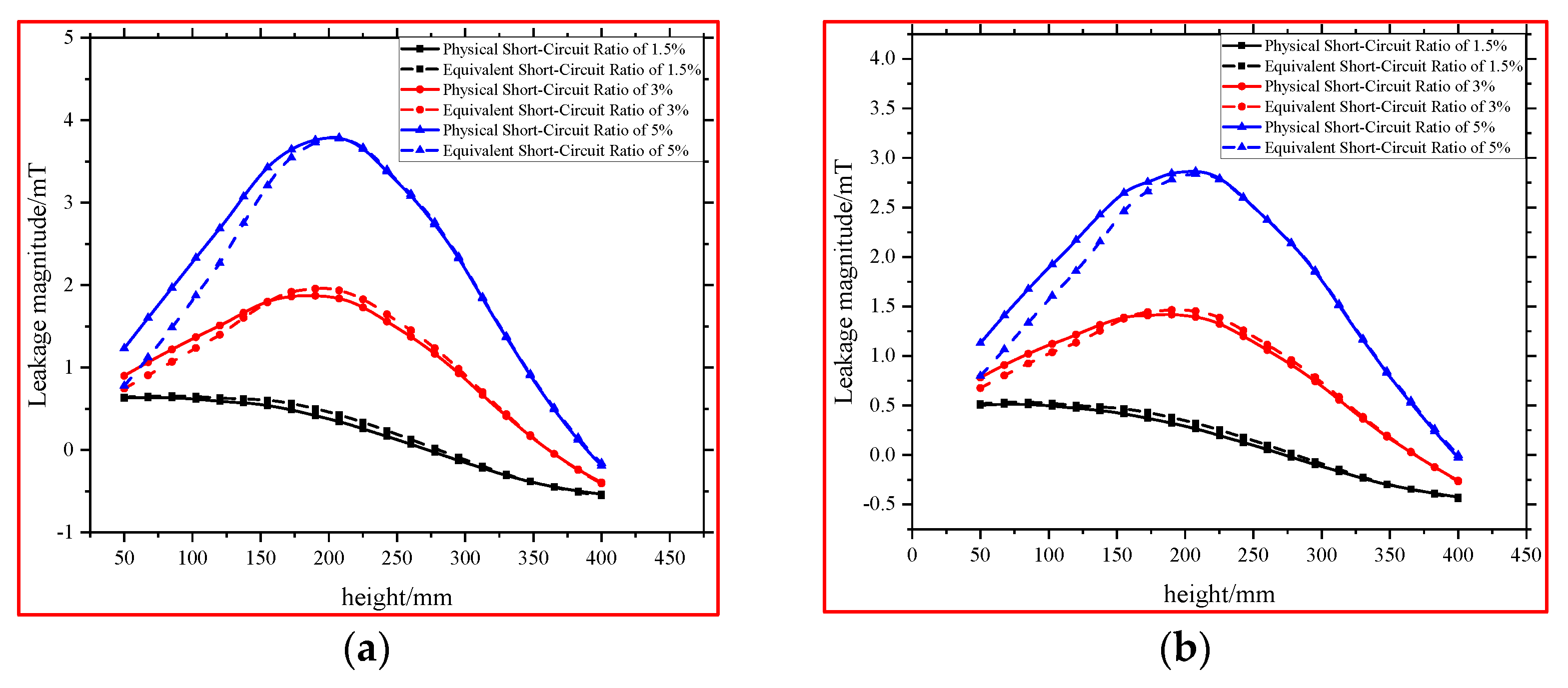
Under different short-circuit proportions, the simulated radial leakage magnetic field distributions of the actual inter-turn short-circuit model and the third-winding-based simulated inter-turn short-circuit model are illustrated in Figure 6 below.
As can be observed from Figure 5, the intensity of the leakage magnetic field in the space rapidly increases with the rise in short-circuit proportion. When the inter-turn short-circuit proportion differs, the variation trends and overall characteristics of the radial leakage magnetic field in both the actual inter-turn short-circuit model and the third-winding-based simulated inter-turn short-circuit model remain identical after fault initiation. Analytical calculations reveal an average discrepancy of less than 5% between the two models. Consequently, the short-circuit proportion exerts negligible influence on the equivalence of the inter-turn short-circuit simulation method in terms of magnetic effects. Therefore, the inter-turn short-circuit simulation method proposed in this paper demonstrates equivalence to actual inter-turn short-circuit faults with respect to fault proportion.
In summary, simulation model analyses verify that critical factors such as magnetic coupling degree, inter-turn short-circuit position, and proportion have no impact on the equivalence of the third-short-circuit-winding-based simulation method for inter-turn short-circuit faults. The proposed simulation method achieves equivalence to actual inter-turn short-circuit faults in both electrical and magnetic effects.

4. Experimental Validation of Winding Equivalence

To further validate the equivalence of the third-short-circuit-winding-based simulation method for inter-turn short-circuit faults and the accuracy of the simulation model and results, a single-phase transformer inter-turn short-circuit fault simulation platform was constructed. Under existing experimental conditions, the effects of inter-turn short-circuit position and proportion on short-circuited turn currents and radial leakage magnetic fields were investigated, and the equivalence of simulation data and the simulation method was verified.

4.1. Experimental Platform Configuration

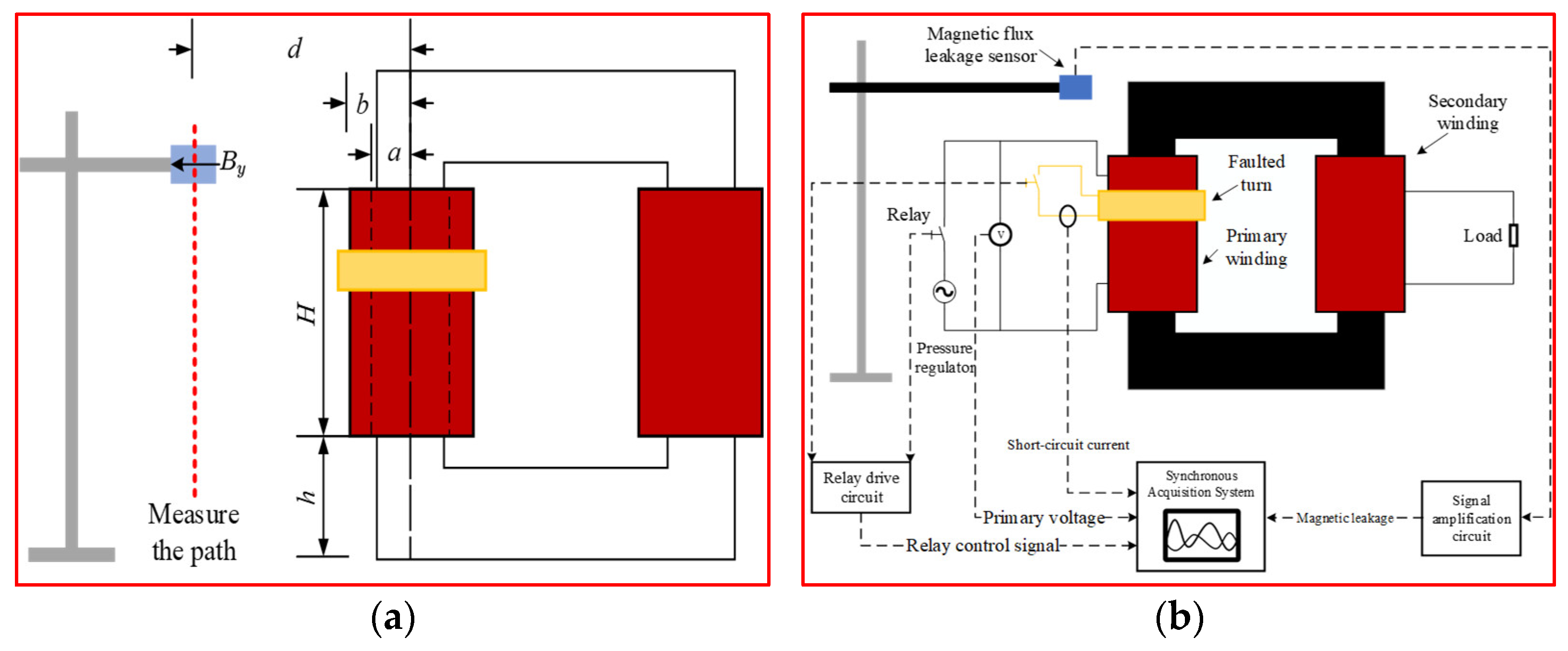
Based on a 0.4/0.4 kV-7 kVA single-phase dual-winding transformer, this study constructed an inter-turn short-circuit simulation experimental platform utilizing a third short-circuit winding. The transformer parameters are listed in Table 1. The primary side of the transformer was connected to an adjustable AC power supply, while the secondary side was loaded with its rated capacity. The inter-turn short-circuit fault was implemented through an external short-circuit winding method, employing two electromagnetic relays to control the on/off status of the transformer’s main circuit and the integration of the short-circuit winding into the transformer loop. A relay driver circuit was designed to control the electromagnetic relays’ operation, achieving electrical isolation to further ensure experimental safety. The relay contacts were fabricated from silver-copper alloy, with measured contact resistance of approximately 5 mΩ. The schematic diagram of the experimental simulation platform is illustrated in Figure 7.
Concurrently, a multi-physical-quantity synchronized measurement platform was established based on the experimental setup, comprising flux leakage sensors, signal amplifiers, current sensors, and a synchronized acquisition system to simultaneously capture radial flux leakage signals and current signatures during transformer inter-turn short-circuit faults. For experimental safety considerations, the flux leakage sensors were positioned at locations remote from the transformer windings, measuring radial flux leakage signals along the axial direction of the windings. The distance d between the sensor measurement path and the winding center was maintained at 225 mm. The flux leakage measurement paths and the equipment layout of the experimental platform are depicted in Figure 8.

4.2. Experimental Validation

In this experiment, multiple inter-turn short-circuit operating conditions were configured based on simulation parameters. For fault settings, inter-turn short-circuit faults with proportions of 1.5%, 3%, and 5% were implemented at two positions relative to the transformer winding height: 15% and 50%. The short-circuit current within the short-circuited turns and the radial leakage magnetic field distribution outside the transformer windings were acquired via the multi-physical-quantity synchronous acquisition system.

4.2.1. Validation of Inter-Turn Short-Circuit Current

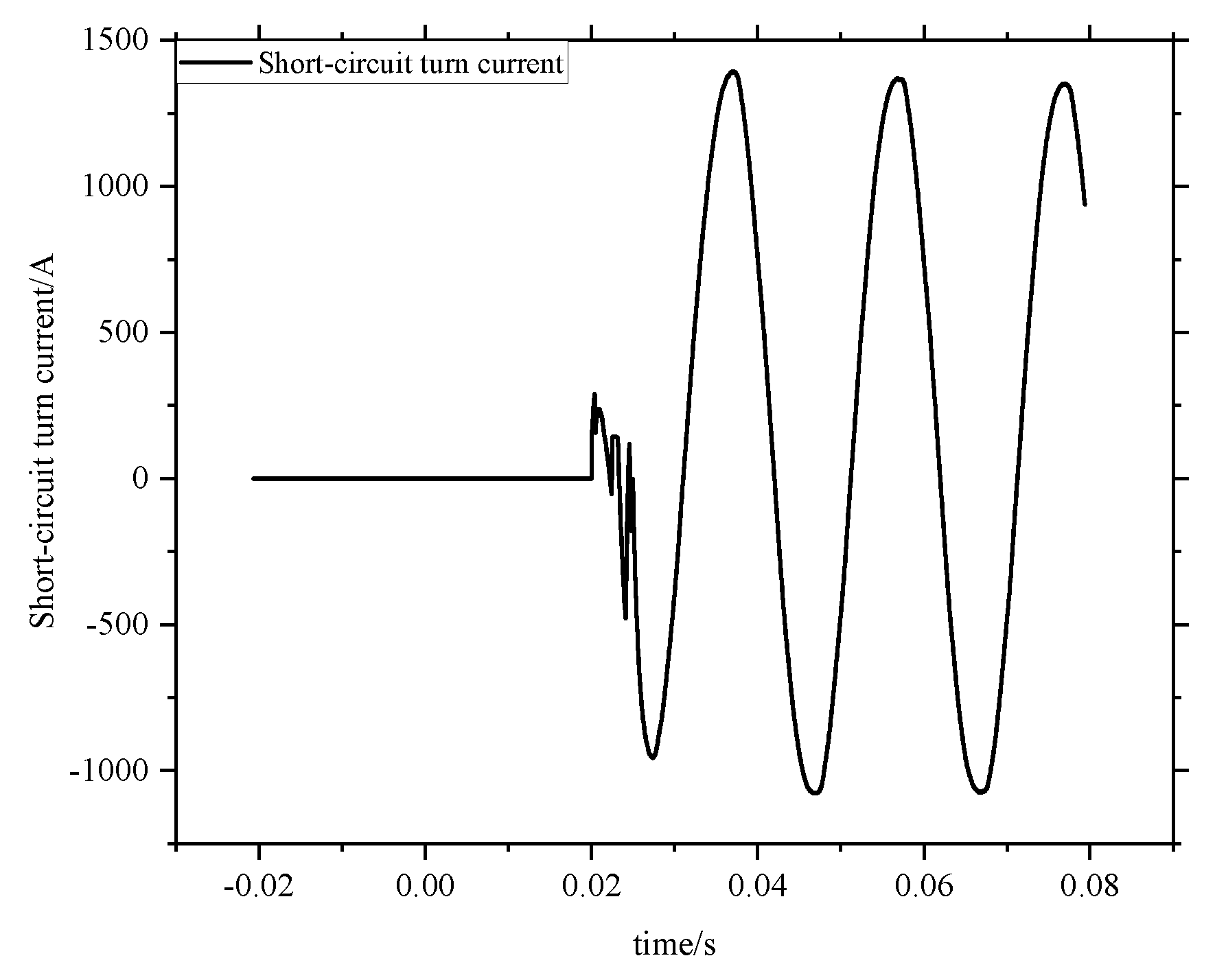
As shown in Figure 9, the short-circuit current measured in the inter-turn short-circuit fault simulation platform corresponds to a 3% short-circuit proportion at 15% relative winding height. When the simulated short-circuit winding was disconnected from the transformer circuit, the current in the short-circuited turns remained zero. After the control relay connected the short-circuited turns to the circuit, a short-circuit current exceeding thousands of amperes (approximately fifty times the rated current) was induced in the short-circuited turns. Simultaneously, a high-frequency oscillation lasting approximately 5 ms occurred during the switching-to-conduction transient. This phenomenon is attributed to minor mechanical vibrations during relay closure and arcing at the relay contacts.
The short-circuited turn currents under different inter-turn short-circuit positions at a short-circuit proportion of 1.5% are listed in Table 4.
The short-circuited turn currents under different inter-turn short-circuit proportions when the short-circuit position is at 15% of the relative winding height are shown in Table 5.
Due to the symmetry of currents and leakage magnetic field distribution in inter-turn short-circuit faults at symmetrical positions of relative winding height, only two short-circuit heights of 15% and 50% were tested in the experiment. The data in the table show that the errors between simulated and experimental current data are below 1%, experimentally verifying the accuracy of the simulated current data and the electrical effect equivalence between the inter-turn short-circuit simulation method and actual inter-turn short-circuit faults.

4.2.2. Validation of Radial Leakage Magnetic Field in Inter-Turn Short Circuits

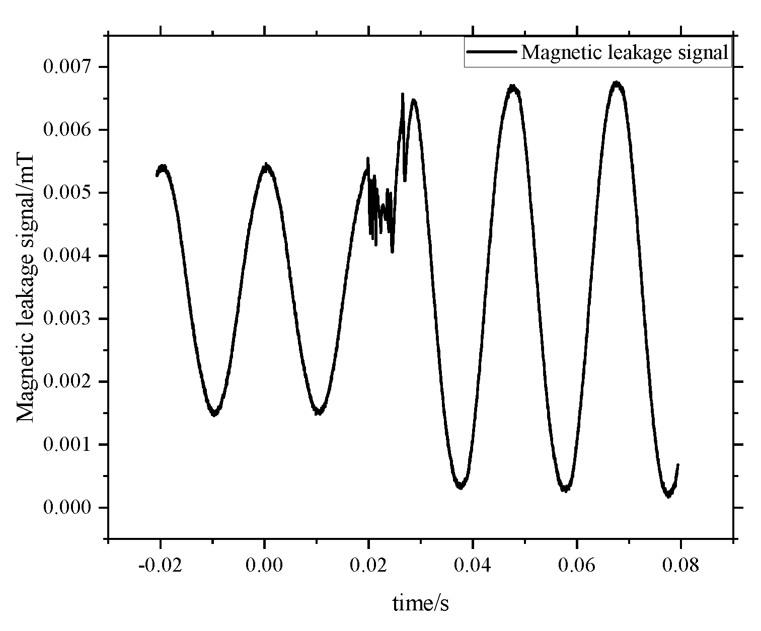
As shown in Figure 10, the radial leakage magnetic field signal measured at the 50% axial height of the relative winding is presented for a 1.5% inter-turn short-circuit fault occurring at 15% relative winding height in the short-circuit fault simulation platform. The figure demonstrates that when the simulated short-circuit winding is not connected to the transformer circuit, the radial leakage magnetic field of the transformer corresponds to normal operating conditions with smaller amplitudes. However, after connecting the simulated short-circuit winding to the transformer circuit, the large short-circuit current in the short-circuited turns generates significant leakage magnetic fields nearby, causing both phase and amplitude changes in the transformer’s leakage magnetic field. Simultaneously, due to transient high-frequency oscillations in the short-circuit current caused by various factors during the relay switch closing instant, correlated high-frequency oscillations are observed in the transformer’s radial leakage magnetic field.
The radial leakage magnetic fields under different inter-turn short-circuit proportions when the short-circuit position is at 15% of the relative winding height are shown in Figure 11.
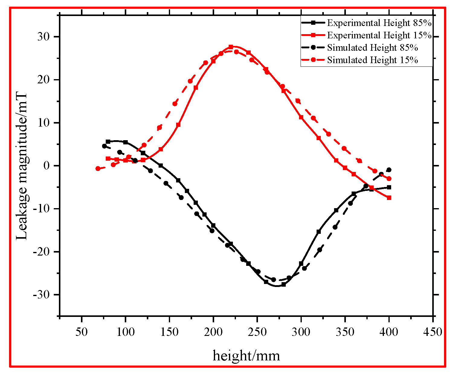
The radial leakage magnetic fields under different inter-turn short-circuit positions when the short-circuit proportion is 5% are shown in Figure 12.
As can be seen from Figure 11 and Figure 12, the simulated radial leakage magnetic data and experimental radial leakage magnetic data under different inter-turn short-circuit proportions and positions are nearly identical, with an average waveform error below 5%. The full-scale experiments validate the accuracy of the simulated radial leakage magnetic data and demonstrate the equivalence in magnetic effects between the inter-turn short-circuit simulation method and actual inter-turn short-circuit faults.
In summary, by constructing a single-phase transformer inter-turn short-circuit experimental platform and conducting full-scale experiments under varying inter-turn short-circuit proportions and positions, the accuracy of the transformer inter-turn short-circuit simulation model is verified. Furthermore, this work confirms the equivalence in both electrical and magnetic effects between the proposed inter-turn short-circuit simulation method and actual inter-turn short-circuit faults.

5. Conclusions

To address the challenges of conducting full-scale experiments due to the enormous short-circuit currents in inter-turn short-circuit faults, this study accomplishes the following:
  • An experimental method utilizing an external third short-circuit winding to simulate inter-turn short-circuit faults is proposed. This method improves the current-carrying capacity, thermal dissipation conditions, and control strategies of the short-circuit winding, enabling it to withstand short-circuit currents up to tens of times the rated current without damaging the transformer’s normal winding structure, ensuring safety and repeatability.
  • A simulation model for inter-turn short-circuit faults in a single-phase dual-winding transformer is developed. The study investigates the primary/secondary winding currents, short-circuit winding currents, and spatial leakage magnetic field distributions under the influence of magnetic coupling degree, short-circuit positions, and proportions. This validates the equivalence in electrical and magnetic effects between the third short-circuit winding simulation method and actual inter-turn short-circuit faults.
  • A single-phase dual-winding transformer inter-turn short-circuit simulation platform is constructed. The accuracy of the simulation model is verified, further confirming the equivalence of the proposed inter-turn short-circuit fault simulation method. Additionally, the short-circuit current in the third short-circuit winding and the radial leakage magnetic field distribution after transformer inter-turn short-circuit faults are analyzed.
This research achievement provides a novel approach for prototype testing of transformer inter-turn short-circuits, but due to specific constraints, only the equivalence on single-phase dual-winding transformers has been validated. Therefore, validation under other complex operational conditions is still required. Subsequent studies will further investigate the equivalence and safety of this inter-turn short-circuit simulation method in higher-voltage three-phase transformers, aiming to enhance the generalizability of this equivalent methodology.

Author Contributions

Conceptualization, C.Y., Z.Z. and Y.S.; methodology, X.L. and L.Y.; software, C.Y. and D.W.; validation, X.L., D.W. and Y.S.; formal analysis, C.Y.; investigation, X.L.; resources, Z.Z. and L.Y.; data curation, X.L. and D.W.; writing—original draft preparation, X.L.; writing—review and editing, C.Y., Y.S., L.Y. and D.W.; visualization, X.L.; supervision, C.Y., L.Y. and Y.S.; project administration, L.Y.; funding acquisition, Z.Z. and L.Y. All authors have read and agreed to the published version of the manuscript.

Funding

This research was funded by Changji Hui Autonomous Prefecture JieBangGuaShuai Project, Research on high energy discharge monitoring and identification technology of power transformer (2023).

Institutional Review Board Statement

Not applicable.

Informed Consent Statement

Not applicable.

Data Availability Statement

The original contributions presented in this study are included in the article. Further inquiries can be directed to the corresponding author.

Conflicts of Interest

Authors Chun Yang, Yuanming Shuai, Dongyang Wu were employed by the TBEA Electrical Equipment Group Co., Ltd. Author Zhengyang Zhang was employed by the TBEA Co., Ltd. The remaining authors declare that the research was conducted in the absence of any commercial or financial relationships that could be construed as a potential conflict of interest.

References

  1. Laayati, O.; El Hadraoui, H.; Bouzi, M.; Chebak, A. Smart Energy Management System: Oil Immersed Power Transformer Failure Prediction and Classification Techniques Based on DGA Data. In Proceedings of the 2022 2nd International Conference on Innovative Research in Applied Science, Engineering and Technology (IRASET), Meknes, Morocco, 3–4 March 2022. [Google Scholar] [CrossRef]
  2. Sriyono, S.; Khayam, U.; Suwarno, S. SFRA Characteristics of Power Transformer Internal Winding Considering the Resonant Effect. In Proceedings of the 2020 8th International Conference on Condition Monitoring and Diagnosis (CMD), Phuket, Thailand, 25–28 October 2020; pp. 302–305. [Google Scholar] [CrossRef]
  3. Cai, Y.; Yu, D.; He, Y.; Ding, K. Research on Fault Diagnosis Method of Transformer Winding Based on Transient Signal and Frequency Response Information. In Proceedings of the 2025 IEEE International Conference on Power Systems and Smart Grid Technologies (PSSGT), Chongqing, China, 11–13 April 2025; pp. 176–182. [Google Scholar] [CrossRef]
  4. Chunyan, Z.; Bingyang, L.; Dandan, Z.; Peng, L.; Shuqi, Z.; Huanchao, C. Research on the Checking for Anti-short Circuit Ability of 500kV Power Transformer. In Proceedings of the 2023 IEEE 6th International Electrical and Energy Conference (CIEEC), Hefei, China, 12–14 May 2023. [Google Scholar] [CrossRef]
  5. Yan, C.; Liu, H.; Yang, H.; Yang, X.; Zhang, P.; Zhang, B. Toward a Novel Characterization of Transformer Interturn Faults Based on Arc-Induced Transients in Winding Magnetomotive Force. IEEE Trans. Magn. 2024, 60, 1–6. [Google Scholar] [CrossRef]
  6. Farzin, N.; Vakilian, M.; Hajipour, E. Transformer Turn-to-Turn Fault Protection Based on Fault-Related Incremental Currents. IEEE Trans. Power Deliv. 2019, 34, 700–709. [Google Scholar] [CrossRef]
  7. Quan, Y.; Zhang, Z.; Chen, G.; Wang, D. Research on detection method of transformer interturn short circuit based on wavelet analysis. Appl. Mech. Mater. 2014, 521, 358–361. Available online: https://www.scientific.net/AMM.521.358 (accessed on 22 September 2025).
  8. Quan, Y.; Zhang, Z.; Chen, G.; Wang, D. Study on Method Detecting Turn-to-Turn short circuit of Transformer Based on Kalman Filter. Appl. Mech. Mater. 2014, 521, 371–374. Available online: https://www.scientific.net/AMM.521.371 (accessed on 22 September 2025).
  9. Zou, D.; Hou, X.; Quan, H.; Zhou, T.; Peng, Q.; Wang, S.; Dai, W.; Hong, Z. Transformer Inter-Turn Short-Circuit Fault Recognition Based on Deep Learning. In Proceedings of the 2024 5th International Conference on Clean Energy and Electric Power Engineering (ICCEPE), Yangzhou, China, 9–11 August 2024; pp. 1002–1010. [Google Scholar] [CrossRef]
  10. Chen, Z.; Yang, R.; Wang, J.; Xiang, N.; Liu, X. Simulation Analysis and Scaling Test of Transformer Turn to Turn Short--Circuit Transient Characteristics Based on Field-Circuit Cooperation. IEEJ Trans. Electr. Electron. Eng. 2025, 20, 1016–1024. [Google Scholar] [CrossRef]
  11. Su, Z.; Luo, L. Research on inter-turn short-circuit fault of power transformer by using third harmonic. IET Renew. Power Gener. 2023, 17, 2791–2800. [Google Scholar] [CrossRef]
  12. Prasad, U.R.; Vyjayanthi, C.; Jaison, K. Modeling and Detection of Inter-turn Faults in Distribution Transformer. In Proceedings of the 2019 8th International Conference on Power Systems (ICPS), Jaipur, India, 20–22 December 2019; pp. 1–6. [Google Scholar] [CrossRef]
  13. Zheng, X.; Xian, R.; Wang, L.; Chen, L.; Hu, Y.; Hao, H.; Liu, G. Online identification method for inter-turn short-circuit fault of grounding transformer winding and phase distinction. Measurement 2025, 256, 118367. [Google Scholar] [CrossRef]
  14. Zhang, T.; Zhou, Q.; Bian, X. Research on Electromagnetic Characteristics of Interturn Short Circuit in Three Phase Transformers. In Proceedings of the 2024 3rd International Conference on Energy, Power and Electrical Technology (ICEPET), Chengdu, China, 17–19 May 2024; pp. 1039–1043. [Google Scholar] [CrossRef]
  15. Wu, Y.; Lin, J.; Ji, T.; Pan, Q.; Huang, S.; Wang, W.; Liu, S.; Jin, Y. Study on Leakage Magnetic Characteristics under Inter-Turn Short Circuit Fault of Transformer. In Proceedings of the 2024 IEEE PES 16th Asia-Pacific Power and Energy Engineering Conference (APPEEC), Nanjing, China, 25–27 October 2024; pp. 1–4. [Google Scholar] [CrossRef]
  16. Peng, Q.; Zhu, X.; Hong, Z.; Zou, D.; Guo, R.; Chu, D. Research into the Fast Calculation Method of Single-Phase Transformer Magnetic Field Based on CNN-LSTM. Energies 2024, 17, 3913. [Google Scholar] [CrossRef]
  17. Zhai, Y.; Li, Q.; Gao, W. Simulation Research on the Influence of Winding Deformation Degree on Transformer Magnetic Field Distribution and Winding Force. In Proceedings of the 2023 IEEE 4th International Conference on Electrical Materials and Power Equipment (ICEMPE), Shanghai, China, 7–10 May 2023; pp. 1–4. [Google Scholar] [CrossRef]
  18. Wang, B.; Wang, L. A fault diagnosis method for inter-turn short circuit based on magnetic field distribution. Sci. Rep. 2025, 15, 1–13. [Google Scholar] [CrossRef] [PubMed]
  19. Haghjoo, F.; Mohammadi, H. Planar Sensors for Online Detection and Region Identification of Turn-to-Turn Faults in Transformers. IEEE Sens. J. 2017, 17, 5450–5459. [Google Scholar] [CrossRef]
  20. Chen, S.; Luo, Y.; Sheng, G.; Jiang, J. Thermal behaviour of a transformer mineral oil--tank surface under incipient turn--to--turn short--circuit fault. IET Sci. Meas. Technol. 2024, 18, 310–323. [Google Scholar] [CrossRef]
  21. Leal, G.G.L.; Meira, M.; Bossio, G.R.; Ruschetti, C.R.; Verucchi, C.J. Inter-Turn Short-Circuit Detection Through Differential Admittance Monitoring in Transformers. IEEE Trans. Instrum. Meas. 2024, 73, 1–8. [Google Scholar] [CrossRef]
  22. Jiang, H.; Feng, J.; Zhao, N.; Xu, H.; Wang, B.; Zhang, B. Fault Diagnosis of Transformer Inter-Turn Short Circuit Based on Automatic Multiscale-Based Peak Detection Algorithm Combined with Magnetic Flux Leakage Analysis. In Proceedings of the 2024 IEEE 13th Data Driven Control and Learning Systems Conference (DDCLS), Kaifeng, China, 17–19 May 2024; pp. 1668–1672. [Google Scholar] [CrossRef]
  23. Ortiz-Medina, R.A.; Aragon-Verduzco, D.A.; Maldonado-Ruelas, V.A.; Olivares-Galvan, J.C.; Escalera-Perez, R. Distinction Between Interturn Short-Circuit Faults and Unbalanced Load in Transformers. Appl. Syst. Innov. 2025, 8, 50. [Google Scholar] [CrossRef]
  24. Fei, L.; Ma, Z.; Cai, L.; Zhou, D.; Shu, X.; Liao, Z.; Lin, C.; Li, X. Analysis of interturn short circuit in regulating winding of power transformer based on field-circuit coupling. Front. Energy Res. 2024, 12, 1393436. [Google Scholar] [CrossRef]
Figure 1. Equivalent method for inter-turn short-circuit fault.
Energies 18 05453 g001
Figure 2. Equivalent circuit diagram of inter-turn short circuit.
Energies 18 05453 g002
Figure 3. Circuit diagram of an equivalent three-winding transformer.
Energies 18 05453 g003
Figure 4. The interval between the third short-circuit winding and the transformer winding.
Energies 18 05453 g004
Figure 5. Distribution of radial leakage field under the influence of short circuit position. (a) At 225 mm from the transformer winding; (b) At 250 mm from the transformer winding.
Energies 18 05453 g005
Figure 6. Radial leakage magnetic field distribution under varying short-circuit proportions. (a) At 225 mm from the transformer winding; (b) At 250 mm from the transformer winding.
Energies 18 05453 g006
Figure 7. Circuit diagram of the inter-turn short-circuit simulation platform.
Energies 18 05453 g007
Figure 8. Inter-turn Short Circuit Test Platform. (a) leakage flux measurement path; (b) Laboratory equipment layout.
Energies 18 05453 g008
Figure 9. Inter-turn short-circuit current signal.
Energies 18 05453 g009
Figure 10. Radial leakage magnetic signals of inter-turn short circuits.
Energies 18 05453 g010
Figure 11. Radial leakage magnetic distribution under different short-circuit proportions.
Energies 18 05453 g011
Figure 12. Radial leakage magnetic distribution under different short-circuit positions.
Energies 18 05453 g012
Table 1. Basic parameters of test transformer.
Transformer ParametersNumeric Value
Rated frequency/Hz50
Power rating/VA7000
Number of turns of the primary winding200
Number of turns of the secondary winding200
Core radius D/mm160
Inner diameter of the primary winding a/mm165
Outer diameter of the primary winding b/mm190
Height of the primary winding above ground h/mm120
Height of the primary winding H/mm240
Table 2. Winding current under the influence of short circuit height.
Simulate Working ConditionsPrimary Current/ASecondary Side Current/AShort-Circuit Turn Current/A
Actual inter-turn short-circuit at 15% height27.512.31010
Actual inter-turn short-circuit at 50% height27.812.41040
Actual inter-turn short-circuit at 85% height27.512.31010
Equivalent inter-turn short-circuit at 15% height27.312.4994
Equivalent inter-turn short-circuit at 50% height27.512.41021
Equivalent inter-turn short-circuit at 85% height27.312.4994
Table 3. Winding current under the influence of short-circuit ratio.
Simulate Working ConditionsPrimary Current/ASecondary Side Current/AShort-Circuit Turn Current/A
Actual inter-turn short-circuit proportion 1.5%27.512.31010
Actual inter-turn short-circuit proportion 3%53.8121390
Actual inter-turn short-circuit proportion 5%71.611.61230
Equivalent inter-turn short-circuit proportion 1.5% 27.312.4994
Equivalent inter-turn short-circuit proportion 3% 52.911.71354
Equivalent inter-turn short-circuit proportion 5% 69.811.41206
Table 4. Short-circuit currents at different inter-turn short-circuit positions.
Short-Circuit ConditionShort-Circuited Turn Current/A
Simulated 15% height994
Experimental 15% height998
Simulated 50% height1021
Experimental 50% height1024
Table 5. Short-circuit currents under different inter-turn short-circuit proportions.
Short-Circuit ConditionShort-Circuited Turn Current/A
Simulated 1.5% short-circuit proportion994
Experimental 1.5% short-circuit proportion998
Simulated 1.5% short-circuit proportion1354
Experimental 1.5% short-circuit proportion1347
Simulated 1.5% short-circuit proportion1206
Experimental 1.5% short-circuit proportion1109
Disclaimer/Publisher’s Note: The statements, opinions and data contained in all publications are solely those of the individual author(s) and contributor(s) and not of MDPI and/or the editor(s). MDPI and/or the editor(s) disclaim responsibility for any injury to people or property resulting from any ideas, methods, instructions or products referred to in the content.