Abstract
To explore possible design solutions for induction motors, we designed and tested a three-phase small-power induction motor with a can-type rotor and a stationary internal ferromagnetic core, a design not previously described in the technical literature. This three-phase motor combines certain features of a reliable solid-rotor motor, a two-rotor layer motor, and a motor in which the rotating thin aluminium layer is separated from the stationary inner ferromagnetic core. The motor prototype was based on a mass-produced, small-power, three-phase squirrel-cage motor. Its operating properties and characteristics were tested, highlighting its potential application as a special-purpose drive or a very interesting case for teaching purposes in laboratories of electrical machines. Measurements confirmed theoretical predictions and enabled the formation of a motor equivalent circuit with shunt and series branch parameters, among which magnetization reactance and rotor resistance varied with rotational speed. The main advantages of the motor are its simple rotor construction, low rotational speed, low-rotor inertia and good dynamics, as well as reliable operation across the entire range of useful torque from no-load to short-circuit conditions, without the risk of overheating.
1. Introduction
Asynchronous motors are among the most commonly used types of electric motors. The most popular mass-produced motors include three-phase squirrel-cage (induction) motors and three-phase slip-ring motors. In both cases, the rotors are slotted. In slip-ring motors, the slots contain distributed three-phase winding. In squirrel-cage motors, the rotor contains a cage made of copper or bronze bars short-circuited by end rings or formed by casting aluminium directly into the rotor slots, simultaneously forming the end rings and fan blades on the rotor’s side surfaces [,,]. The rotor of a slip-ring motor contains easily damageable components, such as distributed windings with insulated wires, slot insulation, front connections, etc. In the squirrel-cage motor, motor failures often result from poor slot filling during the aluminium casting process or mechanical cracking at the connections between the bars and the end rings of the cage caused by rotor overheating or by mechanical bar vibrations [,]. Regarding slip-ring motors, their important advantage is the ease of speed control (without the use of power electronic devices). This can be achieved by inserting external resistance of increasing value into the rotor circuit using slip rings and brushes. A slip-ring motor with a very high value of external resistance in the rotor can be treated as a low-speed motor.
Three-phase motors with solid rotors (which are also termed massive rotors []) are less commonly used. They have worse electromechanical properties (electromagnetic torque is a result of interactions between circular revolving magnetic field developed by a stator and eddy currents induced in the solid rotor), but because of simple rotor construction and lack of easily damageable components, they are regarded as motors with increased reliability. Their rotors may be constructed as either solid ferromagnetic rotors or as two-layer rotors, in which a ferromagnetic core is covered by an aluminium (or copper) layer with higher electrical conductivity (rotor designs with a larger number of layers are also possible) [,,,,].
One example of an unconventional electromechanical converter is a two-phase induction motor (with an elliptical magnetic field revolving along the periphery of the air gap) with a can-type rotor and a stationary internal ferromagnetic core located inside the can (which is also named an inner stator). This type of motor is used as a control system component: a proportional or integral element in automatic control systems. The advantage of this design is a low electromechanical time constant due to the low inertia of the can rotor [,,,,,,,,,,].
The authors decided to combine the construction features of different types of the above-described asynchronous machines to create a small power, low-speed, and low-rotor inertia motor. The thin-walled can provides high rotor resistance, making the motor a low-speed motor (just like a slip-ring asynchronous motor with a high value of external resistance inserted into the rotor circuit). A rotating thin aluminium layer in the form of a can, separated from the stationary inner ferromagnetic core (inner stator), ensures low rotor mass and low rotor inertia. Such a three-phase motor, combining certain features of a reliable solid-rotor motor, a two-rotor layer (aluminium and ferromagnetic) motor and a motor in which the rotating thin aluminium layer is separated from the stationary inner ferromagnetic core, has not been previously described in the technical literature. The combination of the above-listed design features leads to the creation of a motor that can be described as a low-speed motor, a motor with low rotor inertia and a motor with increased reliability (resulting from the lack of easily damageable rotor components).
Driven by curiosity and research inquisitiveness, the authors decided to construct and study the above-described three-phase induction motor (with a circular magnetic field revolving along the periphery of the air gap) with a can-type rotor and a stationary internal ferromagnetic core. The motor was built using a mass-produced, small-power, three-phase squirrel-cage motor as its base. Its operational properties were investigated, with emphasis on potential use as a special-purpose drive as well as an electromechanical converter for teaching purposes in laboratories of electrical machines. Due to its relatively low developed electromagnetic torque and low efficiency, the motor is not suitable for general use; nevertheless, it offers an interesting case from a research perspective and exhibits characteristics that may be useful in special-purpose drive systems. These characteristic features include simple rotor construction and low rotational speed, achievable through direct grid supply without using a power electronics or gearbox. The motor can also operate safely and continuously across the entire range of useful torque, from no-load to short-circuit conditions, without the risk of overheating. Thanks to such properties the motor can be used in household appliances, for example, in the process of thickening, grinding, or crushing food products.
The interesting operating properties of the motor (for example, a slight decrease in the stator current as the motor load increases resulting from a change in the depth of magnetic field penetration into the aluminium can) mean that the motor can also be used in electrical machine laboratories as an interesting and instructive case for educational purposes.
2. Materials and Methods
Construction of a Three-Phase, Low-Speed Induction Motor with a Can-Type Rotor and a Measurement Stand
The prototype of the three-phase, low-speed induction motor with a can-type rotor was constructed using a commercially available low-power, three-phase induction motor (presented in Figure 1) with the following rated data: power P = 90 W, supply voltage 230/400 V (Δ/Y), rated current 0.68/0.39 A (Δ/Y), frequency f = 50 Hz, rotational speed n = 1400 rpm, and power factor cos φ= 0.59. The number of pole pairs is p = 2. As such, the synchronous speed is n0 = 1500 rpm.
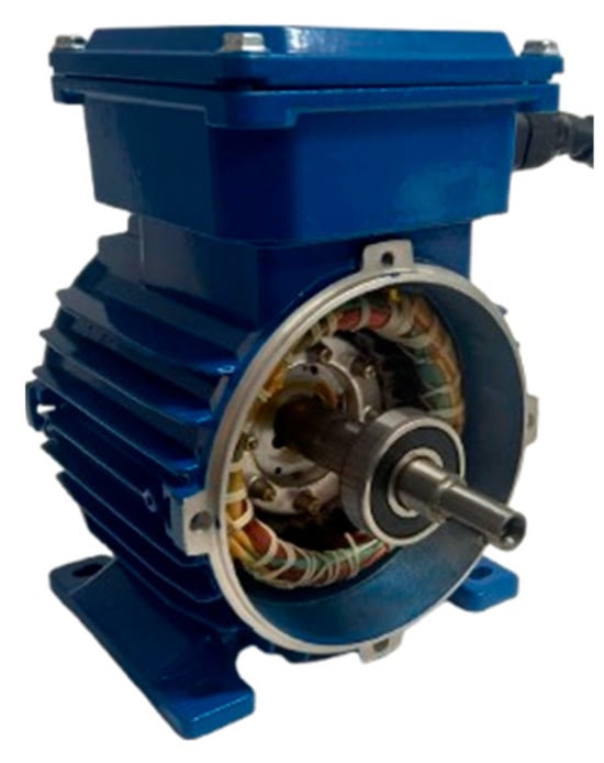
Figure 1.
Three-phase squirrel-cage motor used as the prototype’s base, with the side cover removed.
After removing the squirrel-cage rotor, a thin-walled rotor made from an aluminium tube with a wall thickness Δ = 1.5 m was placed inside of the stator, along with a stationary ferromagnetic core (an internal stator) in the form of a solid cylinder. The can-type rotor was mounted on two bearings located on both sides of the internal stator, secured in place by two Seeger rings and two pressure rings. The procedure for constructing the prototype motor is shown in Figure 2. This configuration will be referred to hereafter as a can-type motor.
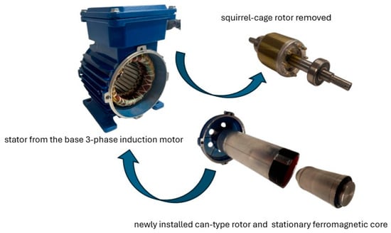
Figure 2.
Procedure for transforming three-phase squirrel-cage motor into three-phase induction motor with can-type rotor.
In the base motor, the air gap was 3 m. As seen in Figure 3, in the prototype, the main air gap between the inner surface of the stator and the outer surface of the aluminium tube was δ1 = 2 m. The thickness of the can was Δ = 1.5 m, and the internal air gap between the inner surface of the can and the outer surface of the internal ferromagnetic core was δ2 = 5 m. This increase in the main air gap from 3 m (in the base motor) to δ1 = 2 m (in the can-type motor) significantly increased the magnetization current and reduced the developed electromagnetic torque. However, the motor also acquired a new property, as its no-load speed shifted significantly into the low-speed range. The stationary internal ferromagnetic core was machined from magnetic steel, as using laminated sheets would be too costly. The total geometric air gap (the sum of the two air gaps and can wall’s thickness) was thus δ1 + Δ + δ2 = 4 m. In calculations, it is necessary to account for the effective air gap, not just the geometric one. The difference between the geometric and effective air gaps in conventional induction motors is due to the saturation phenomenon in the ferromagnetic circuit (the saturation factor) and the slotting of the inner stator surface (the Carter factor). In the case of the can-type motor, it is also necessary to consider the change in the depth of magnetic field penetration into the can rotor, an effect known as the shielding effect [,,,,,].
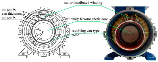
Figure 3.
Cross-section of the can-type motor with essential geometric dimensions marked: main air gap δ1 = 2 m, can thickness Δ = 1.5 m, internal air gap δ2 = 5 m, inner radius of the stator r1 = 2.7 m, outer radius of the can rotor r2 = 2.5 m, and outer radius of the internal stator r3 = 2.3 m.
A specially designed laboratory stand was used to test the three-phase can-type motor and the base three-phase motor, used as a reference. This made it possible to measure stator voltage and current, input electrical power, rotational speed, useful (load) torque, starting torque, and mechanical friction torque [,]. Some components of the laboratory stand were manufactured using 3D printing. Torque measurements were performed using standard methods, including a friction brake and a force gauge (for load torque—Figure 4b) and an electronic measuring scale with a blocking arm (for starting torque—Figure 4a). The laboratory stand was equipped in 4-channel ultra vision oscilloscope and thermal imaging camera.
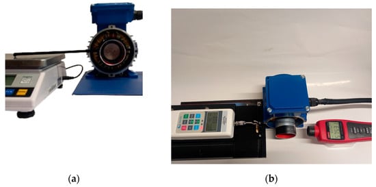
Figure 4.
Laboratory stand (a) part for measuring starting torque (b) part for measuring torque and speed.
3. Results
3.1. Operating Characteristics of the Three-Phase Can-Type Motor
Before the development of power electronics, three-phase slip-ring asynchronous motors were widely used because their speed is easily controlled. This was achieved by inserting external resistance of increasing value into the rotor circuit using slip rings and brushes. In this method of speed control, which is still used today, increasing rotor resistance decreases the slope of the torque–speed characteristic relative to the negative part of the horizontal axis, while the breakdown torque remains unchanged (Figure 5a). Increasing rotor circuit resistance is also accompanied by a reduction in stator current (Figure 5a). The downside of achieving lower rotational speed is increased electrical losses in the rotor and reduced motor efficiency.
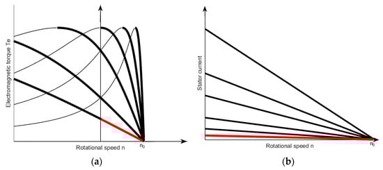
Figure 5.
Speed control of a slip-ring motor achieved by increasing rotor resistance: (a) electromagnetic torque as a function of rotational speed, (b) change in stator current with change in rotor resistance.
Replacing the slotted rotor in an induction motor with a can-type rotor is an extreme form of this method achieved through structural changes to the rotor (indicated by the red lines in Figure 5). The only response to the stator’s rotating magnetic field is eddy currents induced in the thin-walled can, which has high electrical resistance.
To experimentally determine the operating properties of the three-phase can-type motor, it is crucial to determine the allowable supply voltage, which is directly related to the rated current of the base motor. For a star connection, the rated current is In = 0.39 A. All experiments were carried out with the stator winding connected in a star configuration (Y), and all currents, voltages, and parameters were recalculated per phase. Figure 6 shows the rotational speed n and the stator current I as a function of voltage U measured during no-load operation of the can-type motor (at useful torque Tus = 0).
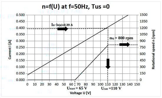
Figure 6.
Stator current I and speed n of the can-type motor as a function of supply voltage U at no-load (Tus = 0).
The motor starts at a voltage Ustart = 65 V based on an average of several measurements taken while increasing and decreasing the voltage. At this value, the developed electromagnetic torque exceeds the mechanical loss torque (friction torque). Note that the base three-phase squirrel-cage motor starts at 45 V. The motor current reaches the rated value In = 0.39 A at a supply voltage of 110 V. This value is considered the rated voltage of the can rotor motor and is denoted as Ucan = 110 V. For the rated voltage, the useful torque–speed curve and stator current–speed curve were measured (Figure 7).
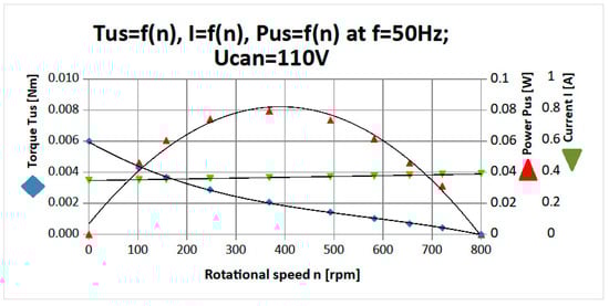
Figure 7.
Can-type motor curves: useful torque Tus, current I, and output power Pus as functions of speed n.
As shown in Figure 7, the useful torque–speed curve differs from the linear form and is slightly concave compared to the red curve shown in Figure 5a. The maximum torque equals the starting torque, Tstart = 0.006 Nm. The no-load speed is 800 rpm. The current–speed curve is particularly interesting. As seen in Figure 7, as speed decreases from no-load (n0 = 800 rpm) to zero (n = 0), the current noticeably decreases by approximately 2.5%. The reason for this behaviour will be explained in the next section. A key conclusion is that the motor can operate safely and continuously throughout the entire torque range, from standstill to no-load speed (n = 0 to n = 800 rpm).
Additionally, Figure 7 includes the output mechanical power curve Pus as a function of speed n. The curve takes the shape of a slightly flattened inverted parabola, with maximum output power occurring at n = 400 rpm and equal to Pus max = 0.8 W. This speed can be considered the rated speed, ncan = 400 rpm. At this power level, the rotational speed is reduced by a factor of approximately four compared to the synchronous speed (n0 = 1500 rpm).
The blocked-rotor curve of the can motor, i.e., starting torque as a function of supply voltage U at n = 0, was also measured (Figure 8).
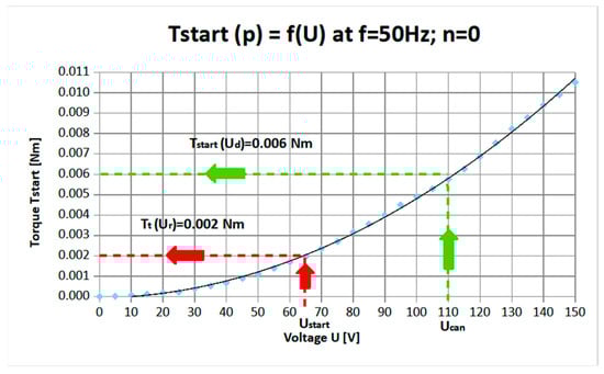
Figure 8.
Blocked-rotor curve of the can-type motor.
This curve can be used to determine the starting torque (green line), Tstart = 0.006 Nm, as well as the mechanical friction torque (red line), Tt = 0.002 Nm. The friction torque was also verified through direct measurement of the unpowered can-type motor.
Based on the useful torque–speed curve and the friction torque value, the electromagnetic torque–speed curve was reconstructed (Figure 9). The friction torque equals approximately 30% of the starting electromagnetic torque.
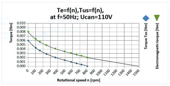
Figure 9.
Electromagnetic torque and useful (load) torque as functions of speed.
3.2. Equivalent Circuit of the Can-Type Motor and Physical Interpretation of Measurement and Calculation Results
In the next stage, an equivalent circuit with shunt and series branch parameters for the three-phase can-type motor was determined. At the beginning, the no-load and rotor-blocked characteristics of the base three-phase squirrel-cage motor were measured. Then, after removing the squirrel-cage rotor, the “cavity characteristic” was determined. Another measurement was taken after inserting the internal ferromagnetic core into the stator cavity of the base motor. Finally, after mounting the can-type rotor on the internal core, the prototype of the can-type motor was tested by recording its no-load and rotor-blocked characteristics. These four current–voltage curves are shown in Figure 10. As can be seen, introducing a stationary ferromagnetic core into the rotor cavity significantly reduced the magnetization current. For example, at a supply voltage of U = 50 V, the magnetization current dropped from 0.42 A to 0.27 A, a nearly twofold decrease.
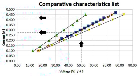
Figure 10.
Comparison of current–voltage curves of the can-type motor: the magnetization curve with both the inner stator and the can removed ( ); the magnetization curve with the inner stator installed and the can removed (
 ); the blocked-rotor curve (
 ); and no-load curve of the complete can-type motor (
 ).
).
It is worth noting that stator current waveforms are practically sinusoidal. This demonstrates the correct choice of the motor supply voltage (no effects related to magnetic circuit saturation). The frequency spectrum of the stator currents also does not show any harmonics related to higher MMF (magnetomotive force) and permeance spatial harmonics. This is because the considered motor with can-type rotor has a thick (compared to the depth of the stator slots) air gap which is slotted only on the stator side (the so-called one-sided slotting) and is smooth on the rotor side. The can-shaped rotor also does not generate higher MMF spatial harmonics [,].
Based on the characteristics of the base three-phase squirrel-cage motor and the prototype of the three-phase can-type motor, the parameters of the equivalent circuit (Figure 11) were determined using a standard methodology [,,,,].
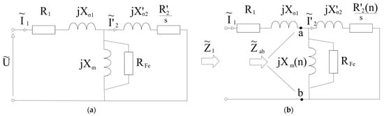
Figure 11.
Equivalent circuit of the three-phase can-type induction motor (a) with speed-independent parameters; (b) with speed-dependent parameters (where s—slip, n—rotor speed).
These include stator resistance R1 = 105 Ω, stator leakage reactance Xσ1 = 40 Ω, magnetization reactance Xm = 255 Ω, equivalent core-loss resistance RFe = 1800 Ω, rotor resistance (referred to the stator) R′2 = 6200 Ω, and rotor leakage reactance X′σ2 = 0 Ω. It was assumed that the calculated and measured results would match at zero speed (n = 0).
Assuming constant values of equivalent circuit parameters (independent of rotational speed-Figure 11a), the electromagnetic torque and stator current as functions of speed were calculated according to the following expressions:
where is air gap power.
A comparison of the calculated and measured results (presented earlier in Figure 7 and Figure 9) is shown in Figure 12.
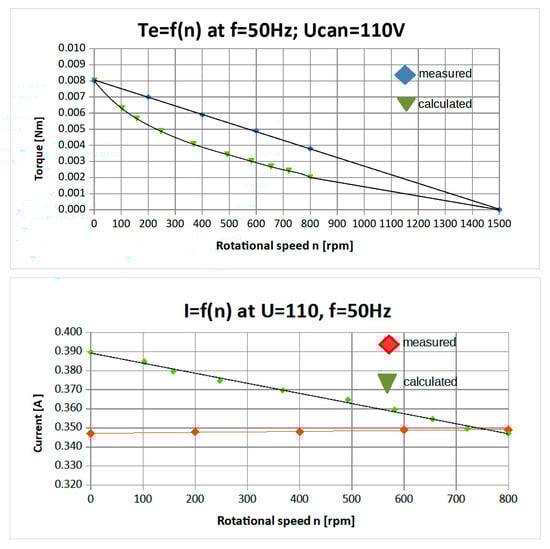
Figure 12.
Comparison of measured and calculated curves of electromagnetic torque and stator current calculations based on the equivalent circuit with constant parameters—Figure 11a.
As expected, there are some discrepancies between the measured and calculated results. These discrepancies arise because as the rotor’s speed increases, the frequency of the eddy currents induced in the can decreases. Consequently, the depth of magnetic field penetration into the aluminium can also changes. This phenomenon can be interpreted as a gradual increase in the effective air gap length, which causes a decrease in the magnetization reactance and an increase in the magnetization current. Simultaneously, rotor resistance increases [,,,,]. To align the calculated and measured results, it is necessary to introduce variable parameters into the equivalent circuit by accounting for the dependence of magnetization reactance and rotor resistance on speed, and , as shown in Figure 11b. Corresponding expressions for the electromagnetic torque and stator current as functions of speed are, as follows:
The determined dependencies: and are presented in Figure 13.
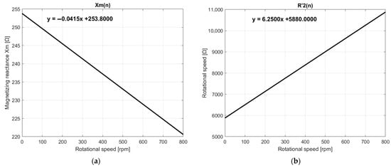
Figure 13.
Variation in equivalent circuit parameters with speed: (a) magnetization reactance; (b) rotor resistance.
They can be analytically described by the following linear functions:
The shape of the magnetization reactance curve as a function of speed, shown in Figure 13, explains the intriguing phenomenon of decreasing stator current when moving from no-load to rotor standstill. As the magnetization reactance decreases, the magnetization current increases, and this component has the most significant effect on the value of the stator current (the rotor current is negligible in comparison). This phenomenon is theoretically interesting, and it could serve as an example in electrical engineering education by illustrating how the depth of magnetic field penetration into a metal layer increases as the supply frequency decreases.
It is also worth noting that the can-type motor has a lower moment of inertia than the base squirrel-cage motor. This reduced inertia allows the can-type motor to accelerate and reach its operating speed faster. This difference in dynamic behaviour is clearly illustrated by the start-up speed curves over time for the squirrel-cage motor (red line) and the can-type motor (blue line), as shown in Figure 14 [,].
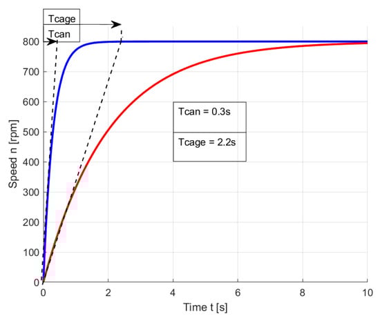
Figure 14.
Start-up speed curves for the squirrel-cage motor and the can-type motor.
The electromechanical time constant of the can-type motor is over seven times smaller than that of the squirrel-cage motor, an additional advantage of this design.
Results from thermal imaging camera are presented in Figure 15. The steady-state rotor temperatures at standstill and no-load speed are remarkably less than in the base three-phase motor. Also, temperatures in the rotor of the prototype motor are favourable in relation to the stator temperatures.
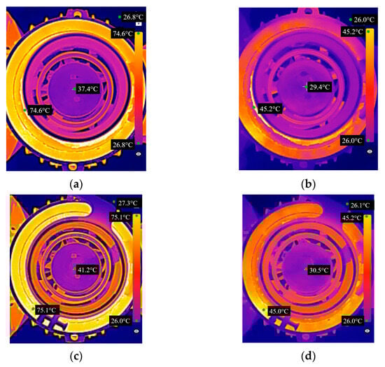
Figure 15.
Thermographs from thermal imaging camera (a) for rotor speed: n = 800 rpm at thermal steady-state (30 min after switching on); (b) for rotor speed: n = 800 rpm, 3 s after switching on; (c) for rotor speed: n = 0 rpm (blocked rotor) at thermal steady-state (30 min after switching on); (d) for rotor speed: n = 0 rpm (blocked rotor), 3 s after switching on.
4. Discussion and Conclusions
Based on a three-phase squirrel-cage motor, a prototype of a three-phase induction motor with a can-type rotor and a stationary inner ferromagnetic core was built. To the best of the authors’ knowledge, this motor has not been previously described in the technical literature. The motor was thoroughly tested, allowing for the determination of its operational characteristics and the most relevant parameters.
The measurements confirmed theoretical predictions and enabled the formation of an equivalent circuit of the motor with shunt and series branch parameters, among which the magnetization reactance and rotor resistance were dependent on rotational speed. The proposed motor has extremely simple rotor construction in the form of an aluminium can. The rotor contains no easily damageable components, such as distributed windings (with insulated wires, slot insulation, and front connections) or a squirrel-cage winding, where common failures results from poor slot filling during the aluminium casting process or mechanical cracking at the connections between the bars and the end rings of the cage [,].
The electromagnetic torque in the can-type motor results from the interaction between the stator current and the eddy currents induced in the rotor, which have unrestricted spatial distribution and intensity (current density). The motor exhibits interesting operational characteristics. Notably, the developed electromagnetic torque increases as rotor speed decreases and reaches its maximum at standstill. This increase in electromagnetic torque is accompanied by a slight reduction in stator current, an intriguing effect related to the changing penetration depth of the magnetic field into the can-type rotor. As rotor speed decreases, both the frequency and amplitude of the induced eddy currents increase, strengthening the so-called shielding effect. This behaviour of the stator current as a function of speed indicates that the motor can operate safely and continuously across the entire torque range, from no-load speed down to zero speed.
Another advantage of the motor is its ability to operate at low speeds when powered directly from the grid without the need for mechanical gearboxes or power electronic control systems. The operating range (i.e., the value of the no-load current) can be easily modified during the design stage by adjusting the can wall thickness, changing the can material (its electrical conductivity), or altering the length of the air gaps. We tested a prototype motor with an extremely thin rotor can, achieving a no-load speed of 180 rpm. In this case, the rated rotor speed, corresponding to the maximum useful power of the motor, was more than 16 times lower than the synchronous speed. This significant reduction in rated speed was accompanied by a reduction in the motor power.
An important benefit is the rotor’s very low mass and low inertia, which allows the motor to respond quickly to changes in load torque or supply voltage. The electromechanical time constant of the can-type rotor motor is seven times lower than that of the mass-produced base motor. This low time constant enables, for example, the generation of oscillatory motion of the rotor via small supply voltage oscillations.
A disadvantage of the can-type motor is its low efficiency and low power-to-mass ratio, which limits its suitability for general use. Instead, it may find application in special-purpose drives where reliable performance and specific operational properties are required. However, the power-to-mass ratio of the rotor itself is favourable. Continued research and theoretical development are recommended.
Author Contributions
Conceptualization, K.K.; methodology, K.K.; software, K.S.; validation, K.S.; formal analysis, K.K. and K.S.; investigation, K.S.; data curation, K.S.; writing—original draft preparation, K.S.; writing—review and editing, K.K.; visualisation, K.S.; supervision, K.K. All authors have read and agreed to the published version of the manuscript.
Funding
This research was conducted at the Faculty of Electrical and Computer Engineering at the Department of Infotronics and Cybersecurity.
Data Availability Statement
The original contributions presented in this study are included in the article material. Further inquiries can be directed to the corresponding authors.
Conflicts of Interest
The authors declare no conflicts of interest. The funders had no role in the design of the study; in the collection, analyses, or interpretation of data; in the writing of the manuscript; or in the decision to publish the results.
References
- Nasar, S.A.; Unnewehr, L.E. Electromechanics and Electric Machines; John Wiley & Sons, Inc.: New York, NY, USA, 1983. [Google Scholar]
- Guru, B.S.; Hiziroglu, H.R. Electric Machinery and Transformers; Oxford University Press: New York, NY, USA, 2001. [Google Scholar]
- Jordan, H.; Klima, V.; Kovacs, K.P. Asynchronmaschinen Funktion, Theorie, Technisches; Akademiai Kiado: Budapest, Hungary, 1975. [Google Scholar]
- Basta, J. Badanie Maszyn Elektrycznych (Testing of Electrical Machines); Wydawnictwa Naukowo-Techniczne (WNT): Warszawa, Poland, 1959. [Google Scholar]
- Godlewski, Z. Uszkodzenia Maszyn Elektrycznych (Damage to Electrical Machines); Wydawnictwo Naukowe PWN: Warszawa, Poland, 1967. [Google Scholar]
- Dąbrowski, M.; Gieras, J. Maszyny Indukcyjne o Wirniku Masywnym (Induction Machines with a Massive Rotor); Państwowe Wydawnictwo Naukowe (PWN): Warszawa, Poland, 1977. [Google Scholar]
- Gieras, J.F.; Saari, J. Performance calculation for a high speed solid-rotor induction motor. IEEE Trans. Ind. Electron. 2011, 59, 2689–2700. [Google Scholar] [CrossRef]
- Jamieson, R.A. Eddy-current effects in solid, unslotted iron rotors. Proc. Inst. Electr. Eng. 1968, 115, 793–800. [Google Scholar] [CrossRef]
- McConnell, H.; Sverdrup, E. The induction machine with solid iron rotor. Trans. Am. Inst. Electr. Eng. 1955, 74, 641–650. [Google Scholar]
- Szczygieł, M. Modelowanie Silnika Indukcyjnego o Dwóch Stopniach Swobody Ruchu oraz Badanie jego Właściwości Eksploatacyjnych Przy Wykorzystaniu Magnetoreologicznego Hamulca Obrotowego-Liniowego (Modeling of a Two-Degree-of-Freedom Induction Motor and Testing of Its Operating Properties Using a Magnetorheological Rotary-Linear Brake). Ph.D. Thesis, Silesian Uniwersity of Technology, Gliwice, Poland, 2011. [Google Scholar]
- Sochocki, R. Mikromaszyny Elektryczne (Electric Micromachines); Wydawnictwa Naukowo-Techniczne WNT: Warszawa, Poland, 1996. [Google Scholar]
- Turowski, J. Obliczenia Elektromagnetyczne Elementów Maszyn i Urządzeń Elektrycznych (Electromagnetic Calculations of Elements of Electrical Machines and Devices); Wydawnictwa Naukowo-Techniczne (WNT): Warszawa, Poland, 1982. [Google Scholar]
- Kluszczyński, K.; Spałek, D. Step-by-Step Analysis of Induction Machines Allowing for Slotting; Polisch Society for Theoretical and Applied Electrical Engineering (Under the Auspices of Electrical Engineering Committee of Polish Academy of Sciences): Warsaw, Poland, 2002. [Google Scholar]
- Kluszczyński, K.; Miksiewicz, R. Modelowanie 3-Fazowych Maszyn Indukcyjnych Przy Uwzględnieniu Wyższych Harmonicznych Przestrzennych Przepływu (Modeling of 3-Phase Induction Machines Taking into Account Higher MMF Spatial Harmonics); Zeszyty Naukowe Politechniki Śląskiej “Elektryka” z.142; Silesian University of Technology: Gliwice, Poland, 1995. [Google Scholar]
- Turowski, J. Elektrodynamika Techniczna (Technical Electrodynamics); Wydawnictwo Naukowe PWN: Warszawa, Poland, 2014. [Google Scholar]
- Wach, P. Dynamics and Control of Electrical Drives; Springer: Berlin/Heidelberg, Germany, 2011. [Google Scholar]
Disclaimer/Publisher’s Note: The statements, opinions and data contained in all publications are solely those of the individual author(s) and contributor(s) and not of MDPI and/or the editor(s). MDPI and/or the editor(s) disclaim responsibility for any injury to people or property resulting from any ideas, methods, instructions or products referred to in the content. |
© 2025 by the authors. Licensee MDPI, Basel, Switzerland. This article is an open access article distributed under the terms and conditions of the Creative Commons Attribution (CC BY) license (https://creativecommons.org/licenses/by/4.0/).