Abstract
Recently, humanoid robots with personification behavior and high working efficiency have received significant attention. Meanwhile, high-torque-density motors, which serve as the core power source for robot joints, have also been widely researched. In this paper, a high-torque-density double-stator permanent-magnet (DSPM) motor is designed for robot joint applications, and its outer stator (OS) split ratio (the ratio between the inner and outer diameters of the OS) and inner stator (IS) split ratio (the ratio between the inner and outer diameters of the IS) are analyzed and optimized. Since the DSPM motor has different heat dissipation capabilities for the OS and IS, their different loss limitations should be considered to avoid the risk of local overheating, especially for the IS. This paper shows that the loss limitations affect the optimal OS and IS split ratios, as well as the maximum average torque. The IS loss limitation increases the optimal OS split ratio and decreases the optimal IS split ratio; however, the OS loss limitation has the opposite effect. Additionally, an investigation into the electromagnetic characteristics of the optimized DSPM motor was conducted using the finite element method. Finally, a prototype was manufactured, and the results of the temperature rise experiments verified the feasibility of the proposed DSPM motor and the effectiveness of the optimal method.
1. Introduction
Dual-stator machines have been widely used in various industrial applications due to their high torque and power density, such as wind power generation [1,2,3], robotics [4], electric vehicles [5,6,7], electric motorcycles [8], and the servo industry [9,10,11]. To achieve high dynamic characteristics in humanoid robots, dual-stator permanent-magnet (DSPM) motors are attractive for applications in robot joint actuators [12,13].
In traditional single-stator PM motors, one of the most crucial parameters is the split ratio, which is defined as the ratio of the stator’s inner diameter to its outer diameter. By balancing the magnetic load and electrical load of the motor, the split ratio can be optimized to maximize the output torque, power density, and efficiency. Reference [14] achieved the minimum copper loss by analyzing the optimal split ratio, and the authors of [15] investigated the influence of the optimal split ratio on the motor magnetic circuit and electromagnetic performance by fixing the copper loss. Reference [16] studied the factors affecting the optimal split ratio, including the drive mode, winding configuration, end-winding, and stator tooth tips. Based on surface PM motors, the authors of [17,18] presented analytical models for computing the optimal split ratio in motors with inner and external rotor configurations. Based on interior PM motors, the optimal split ratio was investigated in [19]. Compared with single-stator motors, dual-stator motors not only need to balance the magnetic load and electrical load but also consider the power ratio of the inner and outer stators. Therefore, the optimal design of DSPM motors can also adopt the optimal split ratio to achieve the maximum torque.
To maximize torque per volume, the authors of [20,21] introduced two split ratios: the outer stator split ratio (outer stator inner diameter/outer stator outer diameter) and the inner stator split ratio (inner stator outer diameter/outer stator outer diameter). In addition, the literature shows that this optimization can be divided into two steps: the first step is the optimization of the outer stator split ratio, and the second step is the optimization of the inner stator split ratio, within the demanded value range. However, this optimal method considers the outer and inner stators separately but neglects the relationship between the inner and outer stators. Based on the same winding connection, packing factor, and wire diameter of the inner and outer stators, the turn ratio (the ratio of the inner and outer stator winding turns) was used as a substitute for the split ratio in [22], and the turn ratio was determined as 1:1, i.e., the same power of the inner and outer air gaps. In [23], only one split ratio was optimized to achieve the maximum torque density, i.e., the ratio of the outer stator inner diameter to the inner stator outer diameter. This split ratio considers the inner and outer stators simultaneously by fixing the sum of the inner and outer stators’ surface current densities and the maximum flux densities of the inner and outer stators. Although the relationship between the inner and outer stator is considered in this method, the proportion of the inner and outer stator power is neglected. Reference [24] introduced the power split ratio, i.e., the ratio of the power of the inner and outer air gaps, to achieve the maximum output power under different magnetic loads. It showed that the optimal power split ratio decreases with an increase in the magnetic load, indicating that the power provided by the inner stator decreases. Compared to the outer stator winding, the inner stator winding exhibits significantly poorer heat dissipation characteristics, and the authors of [25] determined that the power split ratio, i.e., the ratio of the power on the outer stator winding to the rated power of the DSPM motor, should be larger than 0.5. However, “>0.5” is only a qualitative result, not a quantitative result. Therefore, to quantitatively describe the power split ratio while considering the different heat dissipation of the IS and OS, the IS and OS loss limitations are considered during the optimization of DSPM motors.
This paper is organized as follows: The DSPM motor topology is described, and the main parameters of the proposed motor are given in Section 2. Section 3 investigates the optimal split ratio of the DSPM motor considering the IS and OS loss limitations. In addition, the influence of the current density on the optimal split ratio is shown. The electromagnetic performance of the optimized DSPM motor is analyzed in Section 4. Section 5 shows the prototype and its experimental results. Finally, Section 6 provides the conclusion.
2. Motor Topology
A 36-slot/42-pole (36s/42p) DSPM motor is shown in Figure 1a, and it includes an outer stator (OS), an inner stator (IS), and a cup-rotor with outer and inner PMs (OPM and IPM). In addition, a house is designed to support the double stator and rotor, as shown in Figure 1b. With the size limitation of the robot joint, the outer diameter of the house is 114 mm, and its thickness is designed as 4 mm due to the interference fit between the house and OS. Therefore, the outer diameter of the OS is 106 mm. Considering the standardized bearing, the inner diameter of the IS is 54 mm. It is worth noting that the circular fins are designed on the surface of the house to enhance the heat dissipation capacity of the OS by increasing the heat dissipation area. The material of the stator is 20JNEH1200 with 0.2 mm lamination, and that of the PM is N42SH with 1.3 remanence (Br = 1.3). To have a lightweight design, the material of the rotor disk and frame is aluminum alloy (6061-T6). However, a magnetically permeable material, i.e., 10# steel, is used for the rotor yoke. The key design parameters of the proposed DSPM motor are summarized in Table 1.
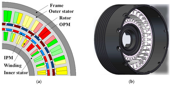
Figure 1.
Motor topology of a 36s/42p DSPM motor. (a) Two-dimensional diagram of the proposed motor; (b) three-dimensional diagram of the house and stators. The red, yellow, and green colors represent the three phase windings.

Table 1.
Main parameters of the proposed DSPM motor.
3. Optimal Split Ratio
3.1. Loss Limitation
Due to two stators and two air gaps, the DSPM motor has an OS split ratio (outer stator inner diameter/outer stator outer diameter), i.e., λOS = Din_OS/Dout_OS, and an IS split ratio (inner stator inner diameter/inner stator outer diameter), i.e., λIS = Din_IS/Dout_IS. Both split ratios are optimized in this paper. For robot joint applications, the maximum winding temperature rise is limited, which depends on the heat dissipation capability, copper loss, and current density. Compared with the conventional single-stator PM motor, the inner and outer stator losses should be considered respectively due to different heat dissipation capabilities, especially for the inner stator. The drive system and end cover obstruct the inner stator’s limited cooling surface, dramatically impairing heat rejection. Therefore, the loss limitation should be considered in the optimization.
Under a uniform winding temperature and exclusive convection heat dissipation, the maximum allowed loss (Plimit) is derived from the motor’s thermal limits [26]:
where h represents the stator effective heat transfer coefficient, a cooling-system-dependent parameter. Its empirical range spans 25–100 W/(m2·K) [27], for natural and forced-air cooling, respectively. Vm is the maximum winding temperature rise, which is fixed by the insulation class (F class, 100K). Do and Ls are the stator outer diameter and stator active length. Therefore, ‘πDoLs’ indicates the heat dissipation area. Table 2 shows the loss limitations of the OS and IS in the DSPM motor. It is worth noting that the heat transfer coefficients of the OS and IS are different, considering the house design.
Table 2.
Loss limitations of the OS and IS in the DSPM motor.
3.2. Torque Calculation
The RMS phase currents (Irms) in windings of the OS and IS are the same due to the series connection, and they can be calculated by the fixed copper loss limitation (Pcu).
where Rph is the phase resistance, ρcu is the copper resistivity, Na is the number of series turns per phase, Ls is the stator active length, Lew is the one side end-winding length, Swire is the copper wire area, Npb is the number of parallel branches, kfill is the slot fill factor, and Sslot and Nslot are the stator slot area and slot number.
Therefore, the electromagnetic torque can be rewritten as
where Kw is the winding factor, Dair is the air-gap diameter, Do is the outer diameter of the stator, λ is the split ratio, D0λ indicates the air-gap diameter, and Bg is the amplitude of the air-gap flux density.
In the DSPM motor, the total torque can be divided into an OS torque and an IS torque, and they can be calculated by the analytical method. It is assumed that the motor has a rectangular open-circuit airgap flux density distribution under FOC control. The OS, IS, and total electromagnetic torque (TOS, TIS, and Ttotal) are given by
where Dair_outer and Dair_inner are the outer and inner air-gap diameters, Bg_outer and Bg_inner are the outer and inner air-gap flux densities, and Na_os and Na_is are the number of series turns per phase in the OS and IS.
In this paper, the air gap length is fixed at 0.4 mm. It is well-known that a smaller thickness of the rotor yoke leads to a larger active slot area. It is designed as 2.2 mm, considering the mechanical strength and manufacturing. In addition, for simplicity, it is assumed that the inner air-gap diameter is equal to the outer diameter of the IS, and the outer air-gap diameter is equal to the inner diameter of the OS.
3.3. Optimal Results
Considering the different stator loss limitations, the optimal results are given and analyzed. The ranges of the IS and OS split ratios can be determined by the ranges of the inner and outer diameters of the OS and IS, respectively. Therefore, in this optimization, the range of the inner diameter of the OS is from 70 mm to 90 mm, and that of the OS split ratio is from 0.66 to 0.85; the range of the outer diameter of the IS is from 60 mm to 80 mm, and that of the IS split ratio is from 0.675 to 0.9.
3.3.1. Torque Considering Outer Stator Loss Limitation Only
When only considering the outer stator loss limitation, Figure 2a shows that the average torque versus OS split ratio follows a parabolic trend (initial increase followed by decrease) for all tested IS split ratios. Therefore, an optimal OS split ratio exists to maximize torque for each IS split ratio. As shown in Figure 3b, the maximum torque diminishes as the IS split ratio decreases.
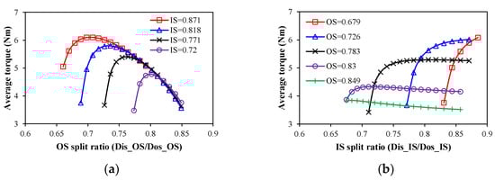
Figure 2.
Variation in average torque with OS and IS split ratios considering outer stator loss limitation only. (a) OS split ratio; (b) IS split ratio.
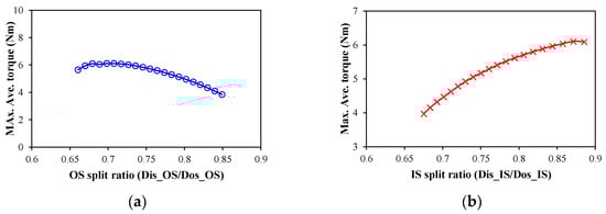
Figure 3.
Maximum average torque versus OS/IS split ratios considering outer stator loss limitation only. (a) OS split ratio; (b) IS split ratio.
However, the trend of the average torque with the IS split ratio depends on the OS split ratio. Figure 2b shows that with a small OS split ratio, such as 0.679 and 0.726, the average torque increases sharply with the increase in the IS split ratio due to the rise of PM thickness. With the relatively large OS split ratio, such as 0.783 and 0.830, the average torque increases sharply at first and then tends to stabilize or even decreases slightly. The reason is that the rise of the PM thickness leads to the rise of the magnetic load and torque at first, while, as the PM thickness increases further, the effect on the magnetic load is weakened, and the electric load decreases. With a large OS split ratio, such as 0.849, the torque decreases with the increase in the IS split ratio. Consequently, for each fixed OS split ratio, an optimal IS split ratio maximizes torque. As shown in Figure 3a, this maximum torque initially rises then diminishes with increasing OS split ratios.
According to Figure 2 and Figure 3, an optimal combination of IS and OS split ratios (λIS = 54/62 = 0.871; λOS = 75/106 = 0.707) exists to maximize the torque, Ttotal_max = 6.104 Nm. However, under this scenario, the outer stator loss is 136.09 W, which significantly exceeds the loss limitation of the IS and results in a high temperature.
3.3.2. Torque Considering Inner Stator Loss Limitation Only
When considering the inner stator loss limitation only, mathematically, the variation in the torque with different IS and OS split ratios is given in Figure 4. It shows that the maximum average torque decreases linearly with the increase in the IS split ratio, and it also increases linearly with the increase in the OS split ratio. In other words, when neglecting the outer stator loss limitation, the torque increases with the increase in the diameter of the air gap. The optimal combination of IS and OS split ratios is λIS = 54/80 = 0.675 and λOS = 90/106 = 0.849, as shown in Figure 4. However, under this scenario, the outer stator loss is 175.49 W, which will lead to a high temperature of the OS.
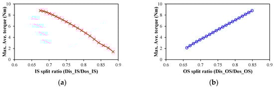
Figure 4.
Maximum average torque versus OS/IS split ratios considering inner stator loss limitation only. (a) OS split ratio; (b) IS split ratio.
Therefore, both the inner and outer stator losses should be considered in the optimization of DSPM motors.
3.3.3. Torque Considering Outer and Inner Stator Loss Limitations
Previous analyses show that the torque variation with IS/OS split ratios exhibits distinctly different behaviors under different limiting conditions. To achieve the maximum torque while maintaining a reasonable temperature rise of the DSPM motor, both the inner and outer stator loss limitations should be considered simultaneously.
The variations in the maximum average torque with IS and OS split ratios considering both inner and outer stator loss limitations are shown in Figure 5. It shows that, for the IS and OS split ratios, the available designs can be divided into two parts: one is dominated by the OS loss, and the other one is dominated by the IS loss. It is worth noting that the available designs in Figure 5 are obtained through a mathematical method. However, the real optimal process is fixing the outer stator loss limitation first and then comparing the inner stator loss limitation. In general, there is a rare available design that has the same inner stator loss as the limitation, as shown in Figure 6. Therefore, there is an optimal combination of IS and OS split ratios, i.e., λIS = 54/70 = 0.771 and λOS = 81/106 = 0.764, to achieve the optimal design, as shown in Figure 6.
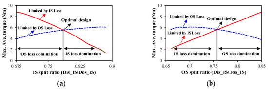
Figure 5.
Maximum average torque versus OS/IS split ratios considering both outer and inner stator loss limitations. (a) IS split ratio; (b) OS split ratio.
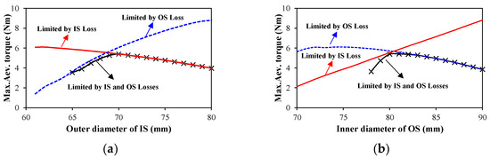
Figure 6.
Maximum average torque versus outer diameter of IS and inner diameter of OS considering outer stator loss limitation firstly and then inner stator loss limitation. (a) Outer diameter of IS; (b) Inner diameter of OS.
Figure 7 shows three optimized motor designs considering the inner stator loss limitation only, the outer stator loss limitation only, and both the outer and inner stator loss limitations, respectively. It indicates that considering either IS or OS loss alone will result in an uneven spatial distribution between the IS and OS, whereas only simultaneous consideration of both IS and OS losses can achieve an optimal motor design.
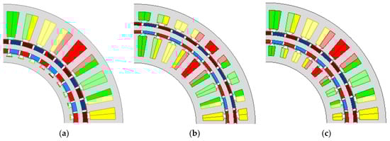
Figure 7.
Motor topologies of the optimized 36s/42p DSPM motors considering different loss limitations. (a) Considering outer stator loss only; (b) considering inner stator loss only; (c) considering inner and outer stator loss. In the OS and IS, the red, yellow, and green colors represent the three phase windings. In the rotor, the red (brown) and blue (light/dark) represent the N-and S-pole.
3.3.4. Torque Considering Current Density
If the copper loss is below the limitation, but the current density is large, the local temperature rise may lead to the insulation breakdown in windings and subsequent short-circuiting. Therefore, after considering the IS and OS losses, the current density also should be limited. Figure 8 shows that the limitation of current density will exclude several designs. When the current density is limited to less than 12 A/mm2, the optimal split ratio remains unchanged. When the current density is limited to less than 10 A/mm2, the optimal split ratio is changed, and the optimal combination of the outer diameter of IS and inner diameter of OS changes from (70 mm, 81 mm) to (71 mm, 80 mm). In high-torque-density DSPM motors, the system operates with a current density not exceeding 12 A/mm2 by engineering experience. The parameters of the optimized DSPM motor are shown in Table 3.
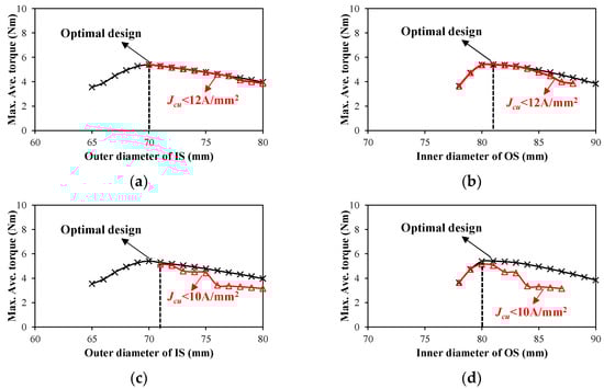
Figure 8.
Maximum average torque versus outer diameter of IS and inner diameter of OS considering different current density limitations. (a) Outer diameter of IS, Jcu < 12 A/mm2; (b) inner diameter of OS, Jcu < 12 A/mm2; (c) outer diameter of IS, Jcu < 10 A/mm2; (d) inner diameter of OS, Jcu < 10 A/mm2.
Table 3.
Parameters of the optimized DSPM motor.
4. Electromagnetic Performance
This section examines the electromagnetic characteristics of the optimized DSPM motor, including open-circuit air-gap flux density, back electromotive force (back-EMF), cogging torque, and electromagnetic torque.
The flux distribution pattern in Figure 9 demonstrates balanced magnetic loading, with theinner stator teeth carrying slightly higher flux density (1.36 T) than the outer stator teeth (1.29 T), while both stator yokes maintain similar sub-0.8 T densities, as shown in Figure 10. The maximum tooth-tip flux densities in the IS and OS are almost 2.0 T, which lead to local magnetic saturation.
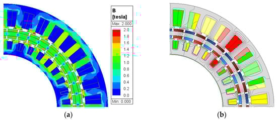
Figure 9.
Equal potential and flux distribution of the optimized DSPM motor. (a) Equal potential. (b) Flux distribution.
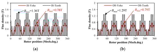
Figure 10.
Flux densities of the inner and outer stator yoke and tooth of the optimized 36s/42p DSPM motor. (a) Inner stator; (b) outer stator.
Figure 11 shows the air-gap flux density and harmonics of the optimized DSPM motor. The air-gap flux density waveforms are trapezoidal, and their harmonics mainly are third order due to the slot effect and local saturation, Figure 11b. It is worth noting that the fundamental component of the inner air-gap flux density exceeds that of the outer air-gap flux density (1.16 T vs. 1.09 T).
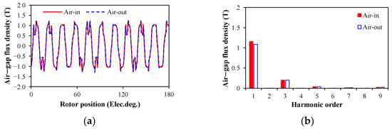
Figure 11.
Air-gap flux densities of the inner and outer air-gaps. (a) Air-gap flux density waveforms; (b) harmonics.
Under the rated operation speed, i.e., n = 1200 r/min, the three-phase back-EMF waveforms of the IS and OS and harmonics of the winding A are shown in Figure 12. The maximum back EMFs of the IS and OS are 8.55 V and 36.1 V, and their back-EMF coefficients are 7.12 V/krpm and 30.08 V/krpm, respectively. The total three-phase back-EMF waveforms of the DSPM motor and harmonics of the winding A are shown in Figure 13. Since the windings of the IS and OS are connected in series, the total three-phase back-EMFs of the DSPM motor are the sum of the three-phase back-EMFs of the IS and OS. Therefore, the maximum phase back EMF of the DSPM motor is 44.65 V.
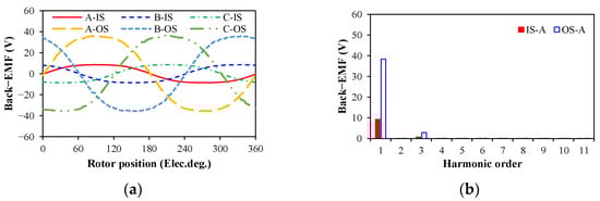
Figure 12.
Three-phase back-EMFs of IS and OS windings. (a) Three-phase back-EMF waveforms; (b) harmonics.
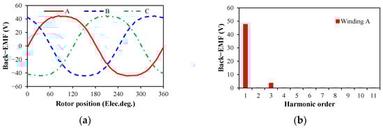
Figure 13.
Three-phase back-EMFs of the optimized DSPM motor. (a) Three-phase back-EMF waveforms; (b) harmonics.
The cogging torque of the optimized motor is shown in Figure 14, and its maximum value is 50 mNm. Figure 15a shows the electromagnetic torque waveform of the optimized motor. The average torque is 4.75 Nm under the rated current (Irms = 5.93 A), and the torque ripple is 3.34%. Figure 15b shows the variation in the average torque with the rms phase current. With the increase in the phase current, the average torque increases, but the slope of the rise decreases due to the electromagnetic saturation.
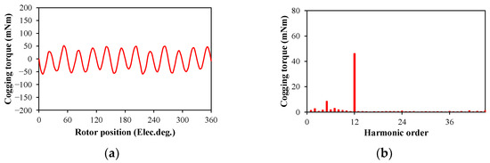
Figure 14.
Cogging torque waveform and harmonics of the optimized DSPM motor. (a) Cogging torque waveform; (b) harmonics.
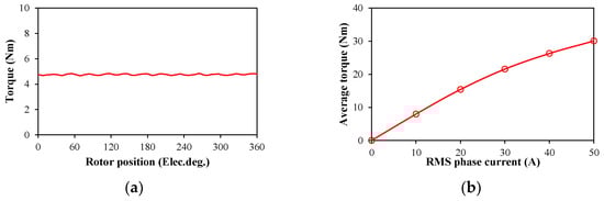
Figure 15.
Electromagnetic torque and torque-current curve of the optimized DSPM motor. (a) Electromagnetic torque waveform; (b) torque–current curve.
5. Experimental Validation
The optimized DSPM motor was manufactured, and its double-stator and rotor structures are shown in Figure 16. Figure 16d shows the 18:1 planetary gearbox. The experiments were carried out, and the measured results validated the analytical and FE predictions. Table 4 presents the measured and FE predicted parameters of the DSPM motor, including the phase resistances and inductances of the IS, OS, and the entire motor. The measured and predicted results have a good agreement.
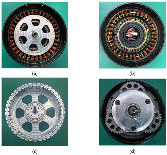
Figure 16.
Prototype of the optimized DSPM motor. (a) Stator and rotor; (b) double-stator structure; (c) rotor structure; (d) 18:1 dual-stage planetary gearbox.
Table 4.
Measured and FE predicted parameters of the DSPM motor.
The close correspondence between the measured and simulated back-EMF waveforms in Figure 17a confirms the accuracy of the FE model’s electromagnetic formulation and parameter assumptions. The FE predicted results of torque and T-I curves of the actuator were validated by the torque test platform. It includes a 200 Nm magnetic particle brake, a torque-speed sensor, and a temperature monitor, as shown in Figure 18. The measured and FE-predicted T-I curves of the DSPM motor are shown in Figure 17b. It shows that the measured torque is smaller than the FE predicted torque of the joint actuator, and the difference mainly is caused by the gearbox losses, the transmission losses of the test bench, the machinal losses of the DSPM motor, and the end effect. Since the efficiency of the 18:1 dual-stage planetary gearbox is almost 85% (The data are provided by the supplier), the measured T-I curve is less than the FE-predicted result, but a satisfactory agreement is achieved, especially for the 85% FE prediction.
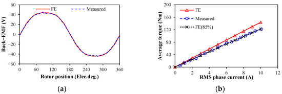
Figure 17.
Measured and FE-predicted back-EMF waveforms and torque–current curves of the DSPM motor. (a) Measured and FE-predicted back-EMF waveforms; (b) measured and FE-predicted torque–current curves.
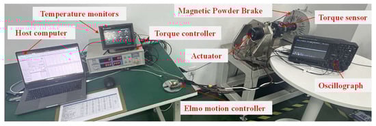
Figure 18.
200 Nm torque test platform.
Additionally, the temperature rise of the various components of the DSPM motor under the rated condition was tested. Figure 19 shows the temperature test points, including the three-phase windings in the IS and OS and the outer and inner walls of the house. The temperature rise curves of various components are shown in Figure 20. After 1500 s (25 min), those temperatures remain almost unchanged, and the winding temperatures of the IS (almost 80.4 °C) are lower than that of the OS (almost 84 °C). In addition, the inner and outer walls of the house remain at 74.3 °C and 60.7 °C, respectively. The temperature results indicate the optimized DSPM motor has good thermal management under the rated condition.
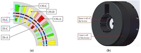
Figure 19.
Temperature test points of the DSPM motor. (a) Test points of the three-phase windings in IS and OS. (b) Test points of the inner and outer walls of the house.
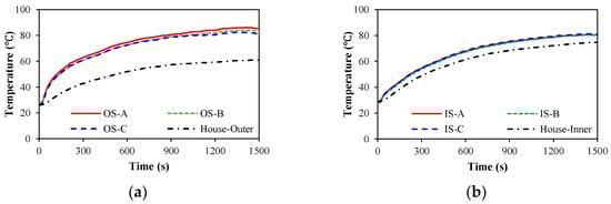
Figure 20.
Temperature test of the DSPM motor. (a) Outer stator; (b) inner stator.
6. Conclusions
This paper proposes a new analytical optimal method for two split ratios of the DSPM motor for humanoid robot joints. Since the heat dissipation capabilities of the inner and outer stators are different, the allowed maximum losses are limited in this optimization, respectively. It shows that both OS and IS loss limitations have a significant influence on the electromagnetic and thermal performance and the optimal combination of OS and IS split ratios. Only limiting the OS loss, the optimal OS split ratio is small, the PM thickness is large, and the IS windings have a high temperature. Only limiting the IS loss, the OS optimal split ratio is large, the PM thickness is small, and the OS windings have a high temperature. Considering both IS and OS losses, the IS and OS windings have the allowed temperature, and the motor has a maximum torque. Finally, the experimental measurements confirm excellent agreement with both FE simulations and analytical predictions, validating the proposed models.
Author Contributions
Conceptualization, T.H.; methodology, T.H.; software, T.H.; validation, Y.S. and W.L.; formal analysis, D.L.; writing—original draft preparation, T.H.; writing—review and editing, Y.S. and D.L. All authors have read and agreed to the published version of the manuscript.
Funding
This research was funded by the National Natural Science Foundation of China (Grant No. 52407062), the Aeronautical Science Foundation of China (Grant No. 20240007038001), and the Shanghai Pujiang Program (Grant No. 22PJD080).
Data Availability Statement
No new data were created or analyzed in this study.
Conflicts of Interest
The authors declare no conflicts of interest.
References
- Levy, D. Analysis of a double-stator induction machine used for a variable-speed/constant-frequency small-scale hydro/wind electric power generator. Electr. Power Syst. Res. 1986, 11, 205–223. [Google Scholar] [CrossRef]
- Niu, S.; Chau, K.T.; Jiang, J.Z.; Liu, C. Design and control of a new double-stator cup-rotor permanent-magnet machine for wind power generation. IEEE Trans. Magn. 2007, 43, 2501–2503. [Google Scholar] [CrossRef]
- Liu, X.P.; Lin, H.Y.; Yang, C.F. 3-D FEA and experiment study of novel dual-stator hybrid excited wind generator. Proc. CSEE 2008, 20, 142–146. [Google Scholar]
- Welburn, R. Ultra high torque motor system for direct drive robotics. In Applications for Today, Proceedings of the Robots 8: Conference Proceedings, Detroit, MI, USA, 4–7 June 1984; Robotics International of SME: Dearborn, MI, USA, 1984. [Google Scholar]
- Chai, F.; Xia, J.; Guo, B.; Cheng, S.K.; Zhang, J.G. Double-Stator Permanent Magnet Synchronous in-Wheel Motor for Hybrid Electric Drive System. IEEE Trans. Magn. 2009, 45, 278–281. [Google Scholar] [CrossRef]
- Zhao, Y.; Huang, W.; Jiang, W.; Lin, X.; Dong, D. Optimal design of double stator permanent magnet motors used in electric vehicle. In Proceedings of the 22nd International Conference on Electrical Machines and Systems (ICEMS), Harbin, China, 11–14 August 2019. [Google Scholar]
- Fan, D.; Quan, L.; Zhu, X.; Xiang, Z.; Que, H. Airgap-harmonic-based multilevel design and optimization of a double-stator flux-modulated permanent-magnet motor. IEEE Trans. Ind. Electron. 2021, 68, 10534–10545. [Google Scholar] [CrossRef]
- Wang, H.; Yan, X.; Huang, S.; Sui, T. Design and torque analysis of dual-stator permanent magnet motor for electric motorcycle. Micromotors 2011, 4, 7–10. [Google Scholar]
- Sugiura, K.; Noguchi, T. Ultra-High-Power-Rate PM motor with double stator structure. In Proceedings of the IEEE Transportation Electrification Conference and Expo, Asia-Pacific (ITEC Asia-Pacific), Chiang Mai, Thailand, 28 November–1 December 2023. [Google Scholar]
- Zheng, B.; Yan, D.; Song, P.; Zhang, Z.; Yan, Y. Optimal design of dual-stator permanent magnet synchronous motors under multiple working conditions. Electric Drive 2025, 1–7. [Google Scholar] [CrossRef]
- Kandil, A.; Hou, L.; Sharaf, M.; Arafa, A.A. Configuration angle effect on the control process of an oscillatory rotor in 8-pole active magnetic bearings. AIMS Math. 2024, 9, 12928–12963. [Google Scholar] [CrossRef]
- Li, R.; Xu, J.; Sun, X.; Chen, J.; Zhang, C. Design of Double Stator Permanent Magnet Synchronous Motor for Robot Joint. Small Spec. Electr. Mach. 2021, 49, 14–18. [Google Scholar]
- He, T.; Liang, D.; Tian, J.; Li, W.; Zhu, Z.Q. Comparative study of permanent magnet synchronous motors with single and double stators for robot joint applications. In Proceedings of the 3th International Conference on Sustainable Mobility Applications, Renewables and Technology (SMART), Dubai, United Arab Emirates, 22–24 November 2024. [Google Scholar]
- Hesmondhalgh, D.E.; Tipping, D.; Amrani, M. Design and construction of a high-speed high-performance direct drive handpiece. IEE Proc. 1987, 134, 286–296. [Google Scholar] [CrossRef]
- Chaaban, F.B. Determination of the optimum rotor/stator diameter ratio of permanent magnet machines. Electr. Mach. Power Syst. 1993, 01, 521–531. [Google Scholar] [CrossRef]
- Pang, Y.; Zhu, Z.; Howe, D. Howe. Analytical determination of optimal split ratio for permanent magnet brushless motors. IEE Proc. Electr. Power Appl. 2006, 153, 7–13. [Google Scholar] [CrossRef]
- Shen, Y.; Zhu, Z.Q. Analytical prediction of optimal split ratio for fractional-slot external rotor PM brushless machines. IEEE Trans. Magn. 2011, 47, 4187–4190. [Google Scholar] [CrossRef]
- Chu, W.; Zhu, Z. Optimal split ratio and torque comparison of surface-mounted permanent magnet machines having inner or outer rotor. In Proceedings of the 6th IET International Conference on Power Electronics, Machines and Drives, Bristol, UK, 27–29 March 2012. [Google Scholar]
- Wu, L.J.; Zhu, Z.Q.; Chen, J.T.; Xia, Z.P.; Jewell, G.W. Optimal split ratio in fractional-slot interior permanent-magnet machines with non-overlapping windings. IEEE Trans. Magn. 2009, 46, 1235–1242. [Google Scholar] [CrossRef]
- Chai, F. Fundamental Research on Double-Stator Integrated Starter Generator for Hybrid Electric Vehicle; Harbin Institute of Technology: Harbin, China, 2003. [Google Scholar]
- Chai, F.; Xia, J.; Gong, H.L.; Guo, B.; Cheng, S.K. Torque analysis of double-stator permanent magnet synchronous for hybrid electric vehicle. In Proceedings of IEEE Vehicle Power and Propulsion Conference, Harbin, China, 3–5 September 2008. [Google Scholar]
- Zhang, D. Design and Analysis of a Novel Double-Stator Permanent Magnet Machine. Ph.D. Thesis, Shanghai University, Shanghai, China, 2007. [Google Scholar]
- Wang, Y.B.; Cheng, M.; Fan, Y.; Chau, K.T. Design and analysis of double-stator permanent magnet brushless motor for hybrid electric vehicles. In Proceedings of International Conference on Electrical Machines and Systems, Wuhan, China, 17–20 October 2008. [Google Scholar]
- Wang, Y.B.; Cheng, M.; Hua, W. Analysis and optimization of split ratio for double-stator permanent magnet brushless machine. Proc. CSEE 2010, 30, 62–67. [Google Scholar]
- Yang, S.; Zhang, F.; Zhang, Z.; Liu, H. Design of double stator permanent magnet synchronous motor with low speed large torque. In Proceedings of IEEE Student Conference on Electric Machines and Systems, Huzhou, China, 14–16 December 2018. [Google Scholar]
- Bianchi, N.; Bolognani, S.; Luise, F. Potentials and limits of high-speed PM motors. IEEE Trans. Ind. Appl. 2004, 40, 1570–1578. [Google Scholar] [CrossRef]
- Levi, E. Polyphase Motors; Wiley: New York, NY, USA, 1984. [Google Scholar]
Disclaimer/Publisher’s Note: The statements, opinions and data contained in all publications are solely those of the individual author(s) and contributor(s) and not of MDPI and/or the editor(s). MDPI and/or the editor(s) disclaim responsibility for any injury to people or property resulting from any ideas, methods, instructions or products referred to in the content. |
© 2025 by the authors. Licensee MDPI, Basel, Switzerland. This article is an open access article distributed under the terms and conditions of the Creative Commons Attribution (CC BY) license (https://creativecommons.org/licenses/by/4.0/).