Abstract
Wireless electric vehicle (EV) charging is an important operation for valuable EV options in modern life. Inductive wireless EV charging needs constant current and voltage (CC–CV) charge controllers. This paper presents 750 W variable frequency CC–CV inductive wireless charging for an e-golf cart 50 Ah 72 V Li-ion battery. Due to this system’s low power, the system’s efficiency may be weak; the secondary-side (SS) maximum efficiency-controlled (MEC) converter was validated. The golf cart’s battery characteristics were evaluated to design and experiment with inductive wireless power transfer (IPT) coils and an integration system for a 42 kHz resonant frequency. The CC–CV charged control is an infrastructural part of the H-bridge inverter at varied frequencies from 50 kHz to 56 kHz when the DC input voltage is 310 V, and in the range of 44 kHz to 46 kHz at the 155 V input. The results found the charging of 9 A CC, 82 V CV and 730 W. The 310 V input voltage system without the SS MEC converter’s efficiencies was 62% to 72% and it was improved to 65% to 81% using the SS MEC converter. Finally, the best cases were validated at the 155 V DC input voltage and the system with the SS MEC converter had 76% to 86% efficiency.
1. Introduction
The rapid advancement of wireless EV charging technology is centered around providing practical and efficient charging alternatives for EVs. This progression addresses resource depletion, pollution and environmental damage from conventional fossil-fuel-powered vehicles [1].
The global EV market has risen enormously in the last 10 years, from 120,000 cars in 2012 to over 16.5 million in 2021, and has tripled over the last three years during the COVID-19 pandemic. The success of the global EV market has been driven by sustainable clean energy policy support from governments, the inclusion of incentives and subsidies in financial and economic acts and the public perception of EVs as being zero-waste [2,3].
In 2022, oil prices were challenged due to the fallout from the crises of the COVID-19 pandemic, the war in Ukraine and the stress in the Taiwan Strait. This situation imposed enormous constraints on the global energy supply chains, leading to a surge in fossil fuel prices and a lack of semiconductor chips and critical minerals [4]; that is, there was an opportunity to accelerate the global energy transition from fossil to clean technologies. Thus, EVs may raise global demand, but EVs’ battery and chip supply chains may push EV prices higher in the short term.
In mid-2022, EV producers like Tesla, Rivian and Ford raised the battery-powered and EV model tag prices. In addition, inflation has been turning EVs into the category of luxury items; so, customers who can buy new EVs may be limited in terms of wealth [5].
Wireless EV charging is a luxury operation for modern-lifestyle EVs that do not need physical coupling of the transmitter to the receiver [1,2,6]. The automatic processes of wireless EV charging are more suitable and safe for drivers, especially for women, the elderly or people with disabilities. Moreover, automated wireless charging can include touching charging devices and surfaces, which may have some droplets of coronaviruses from the users [2,6]. A wireless EV charging system is an intelligent device developed for luxury customers.
Wireless EV charging may develop from the two leading technologies: inductive wireless power transfer (IPT) and capacitive wireless power transfer (CPT) [7]. IPT uses a high frequency of magnetic flux linking the transmitter (Tx) coils and the receiver (Rx) coils. IPT supplies higher output power and efficiency; see [6,8].
IPT is used for LED TVs [9], e-kettles [10], e-scooters [11], e-bikes and motorcycles [12,13], solar tricycles [14], EV chargers and stations [15,16] and wireless power transfer units [17,18,19,20]. A few IPTs have been applied in wireless golf cart charging [21,22,23]. Wireless power transfer is a luxury technology for the future intelligent society.
Small and light battery micro-EV cars such as the L7e car, e-Tuk-Tuk and e-golf cart have been encouraged for development and conversion from fossil fuel engines to EVs in Thailand by the Electric Vehicle Association of Thailand (EVAT) and the Energy Ministry of Thailand [23,24]. Consequently, Thailand’s industrial EV sectors must learn and develop EV technologies. Wireless power transfer is needed for wireless charging to create golf carts used in sports clubs, gardens, houses, factories and so on. The valuable wireless charging golf cart advances users’ convenience, safety, sporty character and sports intelligence.
The topic of wireless golf cart charging was first publicized in 2016 at KIAST; in particular, it was discussed that the wireless power transfer was designed for high efficiency of up to 96% at a 48 V 20 A 960 W output for a lead–acid battery and a low leakage flux of 20 mG according to the safety guidelines of the ICNIRP 1998/2010 [21]. Then, the golf cart battery charger achieved a 4% efficiency with 21 V 9 A at the resistant load [22]. The wireless golf cart charger was developed in Thailand, reaching 70 to 80% efficiency with 38–40 V 10 A charging for a golf cart’s 36 V lead–acid battery set [23]. The wireless golf cart charging systems were developed only for resistive load testing and the lead–acid battery sets. Still, wireless charging for golf carts powered by lithium-ion batteries had never been released before. These are necessary to study wireless lithium-ion battery golf cart charging using IPT.
IPTs are applied for wireless battery CC–CV charging that needs current- and voltage-controlled devices. The lower (20 to 80%) state of charge (SOC) lowers the internal resistance, conducts a higher charging current and may overcharge the current rating that requires a constant current charge controller. At a higher (>80%) SOC, the battery’s internal resistance retains a higher level and the higher charging current leads to overvoltage of the battery, which requires a constant voltage charge controller. CC–CV charge control is designed for battery safety from the overcurrent and overvoltage charging operation.
The CC–CV control system for inductive wireless EV charging can be divided into three forms: (a) primary-side (PS) controller, (b) SS controller and (c) dual-side controllers. Indeed, the PS converters used the PS control inductive wireless power transfer systems [23,25,26,27,28] and the phase-shift control inverter [29,30,31,32,33,34]. The SS control inductive wireless power transfer system was studied using the phase-shift full bridge rectifier [35] and secondary resonator [36,37]. And the dual-side control for inductive charging uses the techniques of dual-phase shift control, double-side active rectifiers, dual-side DC buck converters, primary inverter–secondary converter, bidirectional inverters, primary converter–secondary rectifier, LLC-S circuit, half-bridge converters and IC chip blocks as published in [38,39,40,41,42,43]. Nevertheless, variable frequencies of CC–CV with the compensated circuitries have been reported [44,45]. Therefore, the wireless IPT applications for EV charging consider the current and voltage of CC–CV charging and the system’s efficiency. However, the variable frequency CC–CV control with maximum efficiency control techniques has never been published.
This paper presents a novel method, variable frequency CC–CV charging via a wireless communications control with a secondary efficiency control prototype, which has never been reported before. This method can verify the battery-charging current and voltage, which depend on the system frequency. In addition, the IPT’s maximum efficiency control (MEC) that can elevate the IPT’s efficiency using the impedance matching the SS converter is evaluated. This study applies varied frequency CC–CV inductive charging with the SS MEC for the Li-ion battery golf cart.
This paper proposes the varied frequency for the CC–CV inductive charger using the wireless communications system with the MEC IPT for an e-golf cart, the experiments, results and discussions and conclusions.
2. Varied Frequency Controlled Inductive Wireless CC–CV Charging for an e-Golf Cart
The varied frequency controller for an e-golf cart IPT CC–CV charger consists of the PS and SS charge controllers. The PS charge controller was constructed from the front-end single-phase rectifier, the variable high-frequency inverter and Tx that was used to control the CC–CV power and energy for the transmitter coils. The SS charge controller was developed using the high-frequency rectifier, without and with the maximum efficiency controlled (MEC) SS buck converter, current and voltage sensing via the NRF2401 wireless communications modules with a 25 ms delay of feedback signals and measuring systems, the stepping-resistant load Li-ion battery simulator and the Li-ion golf cart battery, as shown in Figure 1.
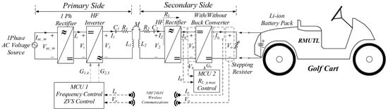
Figure 1.
Varied frequency CC–CV inductive charging for the 50 Ah 72 V Li-ion battery e-golf cart.
2.1. e-Golf Cart Li-Ion Battery and Stepping-Resistant Load Battery Simulator
A sample golf cart powered by a 50 Ah 72 V Li-ion battery was used in this study. Figure 2 shows the model of the sample golf cart with the battery-packed kit. In addition, the coordination of the Tx and Rx coils is defined to describe the related positions of the two coils by the IEC 61980-1 standards [46]. The coordination of the forward misalignment of the two coils from the offset to the X1 position and the forward direction of the EV parking is defined for the X symbol. The coordination of Y is limited to positioning the misalignment from the offset to the left side direction for the positive value of Y. The coordination of Z is described as the distance between the front edges of the two coils. The coordination of XYZ in this study is shown in Figure 2.
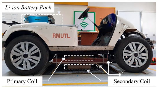
Figure 2.
e-golf cart with the 50 Ah 72 V Li-ion battery.
The preliminary test charging current and voltage characteristics of the sample battery are shown in Figure 3a, where the 9 A charging current for the CC and 82 V charging voltage for the CV charging modes are presented. The sample battery’s SOC and the sample battery’s internal resistance were evaluated and are shown in Figure 3b.
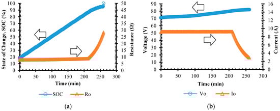
Figure 3.
Voltage, current, SOC and resistant characteristics of golf cart 50 Ah 72 V Li-ion battery. (a) A typical tested voltage and current characteristics. (b) A typical tested SOC and resistance. Directions of y-axes are indicated by arrows.
The stepping-resistant load Li-ion battery simulator was designed and constructed to test the charging operation of the power electronics’ response behaviors and performances. The charging time was reduced to 280 s for testing the power electronics operations to speed up the evaluation of the charge controller performance. The Li-ion battery in the golf cart next underwent a 280-min charging process after the charge controller’s functionality was verified.
2.2. Inductive Wireless Power Transfer (IPT)
The IPT coils’ root mean square output voltage (V2) and current (I2) were evaluated, as shown in Equations (1)–(4). Equations (1) and (2) show the voltage and current, which are functions of the IPT frequency (ω) and can be controlled by the primary-side inverter.
where Z1 and Z2 are specified in Equations (3) and (4)
where the system’s parameters are a primary-side capacitor C1, the primary-side inductive coils that consist of the Tx’s resistance (R1), leakage inductance (L1) and mutual inductance (M) in the middle of Tx and Rx; on the other hand, the SS consists of the SS capacitor (C2), Rx’s resistance (R2), leakage inductance (L2) and IPT’s load resistance (). The circuit diagram of the system’s parameter is shown in Figure 1.
2.3. Variable Frequency CC–CV Control
The inductive coils’ transfer conductance () and transfer admittance () were assessed in order to design a CC–CV feedback PI-controlled system that would adapt to changing switch-gate-drive signal frequencies.
The transfer conductance, the ratio of output current to input voltage of the inductive coils, is shown in Equation (5). The transfer admittance of the inductive coils asserts that the output voltage to input voltage ratio is determined by the product of the transfer conductance and the load resistance, as shown in Equation (6).
The varied frequency CC–CV feedback cascade PI controller, as shown in Figure 4, is applied to the primary-side inverter. The PWM frequency generator for the inverter gate driver changes the frequency to control the CC–CV charging. The MATLAB/Simulink is applied to control the system via the Delfino F28379D microcontroller (MCU).
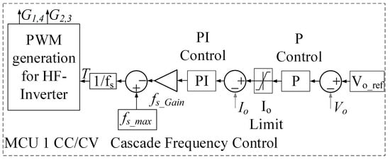
Figure 4.
Primary-side (PS) variable frequency CC–CV control system.
The CC–CV feedback cascade current and voltage controller comprises two control loops. The outer loop is responsible for voltage control, where the voltage error between the reference output voltage (Vo_ref) or the battery terminal voltage and the actual output voltage (Vo) or battery terminal voltage is multiplied by the proportional control gain (kp = 40). This resultant value serves as the reference input for the inner current control loop. In this study, Vo_ref was set to 82 V, corresponding to CV mode charging for a 72 V-rated Li-ion battery. In this case, the limiter function was employed to restrict the reference-controlled current (Io) to a maximum of 9 A during CC mode charging.
For the internal control loop, the discrepancy between Io and the output current (Io) was regulated using a PI controller with a proportional gain (kp) of 1 and an integral gain (ki) of 1000. The output of the internal control loop was further influenced by the switching frequency gain (fS_Gain), set at 6000 Hz. Subsequently, the calculated maximum switching frequency (fS_max) of 56 kHz, as determined by Equation (2), was compared to (fS_Gain). This comparison resulted in an output frequency signal ranging from 50 kHz to 56 kHz. The period (T) of the PWM switching frequency was the reciprocal of the compared frequencies. The PWM generator’s frequency then governed the output gate drive signals for the first and fourth switches (G1,4) and the HF-inverter’s second and third switches (G2,3), utilizing the period to control the voltage and current signals.
2.4. Secondary-Side Maximum Efficiency Control (MEC)
The SS MEC converter is studied in cases without and with the device to compare the system’s efficiencies. Figure 5 presents a diagram of the feed-forward PI controller for the SS MEC buck converter to match the battery’s internal resistances to the inductive coils’ output impedance.
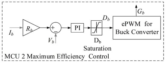
Figure 5.
Secondary-side maximum efficiency control (MEC) feed-forward control system.
The inductive coils’ output power ( equation, Equation (7), is derived from Equations (1) and (2). The coils’ output power is the square function of the system’s frequency, mutual inductance and input voltage, and directed variation to the load resistance or the battery resistance, as shown in Equation (7). Equation (8) illustrates how Equation (7) can be used to determine the efficiency () of the IPT, which is a function of the of the IPT coils.
For charging, the battery’s internal resistance varies with the SOC. The maximum value of η in a function of RL variations can be differentiated, as shown in Equations (9) and (10).
where the IPT’s output resistance for the maximum efficiency ( varied with the IPT frequencies (, shown in Equation (10).
The SS buck converter adjusts the duty cycle (Db) to match the battery resistance () that transfers by a ratio of the SS rectifier, switching signals automatically using a microcontroller 2 (MCU 2) to track the maximum efficiency, using Equations (11) and (12).
Equations (8)–(12) were applied to create the MEC that matches the battery resistance by varying the SS converter’s duty cycle to match the IPT’s output impedance. Equation (10), which multiplies the resistance corresponding to the optimal efficiency by the detected current from the battery, is used to start the process. The output voltage for maximum efficiency is then compared to the battery voltage. This comparison is passed into a saturation limiter block and PI controller block with kp = −1 × 10⁻¹⁰, ki = −4, settings. After that, the duty cycle is applied to the PWM generator for the converter switches.
3. Experiments
The experiments of the varied frequency CC–CV inductive wireless EV charging without and with the SS MEC converter for the e-golf cart system consisted of the processes as shown in Figure 6. Firstly, the stepping-resistant load for a 50 Ah 72 V Li-ion battery simulator was designed. Secondly, we developed and analyzed the characteristics of the inductive coils. Thirdly, the PS inverter and MEC SS converter were designed and built.
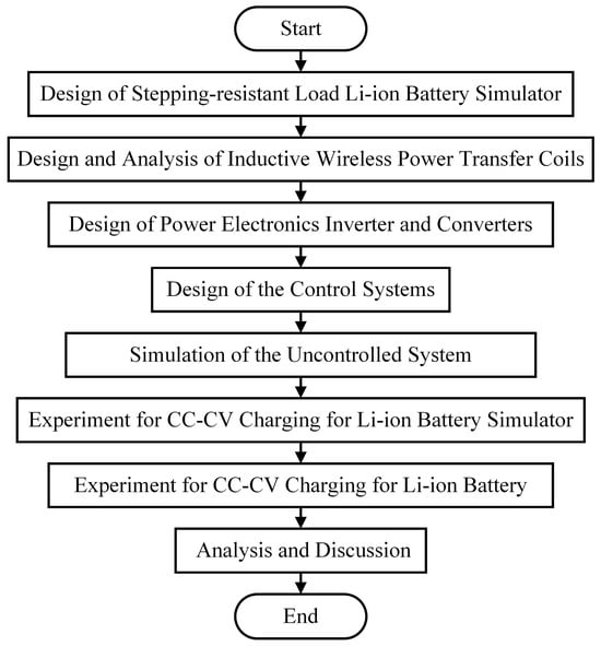
Figure 6.
Processes of the study on varied frequency CC–CV inductive wireless power transfer of EV charging with secondary-side efficiency-controlled converter for electric golf cart.
Then, the control systems for the variable frequency inverter control and impedance matching control were designed, built and tested. After that, the varied frequency CC–CV inductive charging system without and with the MEC SS converter was simulated using MATLAB/Simulink. Next, the performances of CC–CV inductive charging for the e-golf cart were executed and validated by the simulations and the tests. And the experimental results were verified and are discussed.
3.1. Step-Resistant Li-Ion Battery Simulator Design
The advantages of a step-resistant Li-ion battery simulator are low-cost kits, discharge-operation-free, IPT can be performed before the real battery, which has a high cost, and the safety protection is validated. In addition, the power electronics closed-loop controller can be evaluated using the step responses.
The stepping-resistant load Li-ion battery simulator was designed and constructed using the SOC-dependent resistant values. The crushable Li-ion battery simulator’s system charge time was reduced from 270 min to 270 s, allowing faster testing of the charge controller’s response. The ten steps of the resistant Li-ion battery simulator were divided into four stages of the CC mode for 7.8 Ω, 8.1 Ω, 8.4 Ω and 8.9 Ω, and six sets of the CV mode for 10.2 Ω, 11.5 Ω, 13.5 Ω, 16.2 Ω, 20.1 Ω and 26.6 Ω, respectively.
Lamps were built for the step-resistant Li-ion battery simulator because they absorb higher power. The stepping times were controlled using the RGT00TS65D IGBT switches that the gate drives TLP250 signaled from the Development Board Arduino Mega 2560 MCU.
Figure 7 shows the construction of the stepping-resistant load battery simulator controlled by the MCU. Figure 8a shows validations of the battery simulator’s stepping current and voltage characteristics at which the prototype stepping-resistant load was tested. And Figure 8b shows the tested stepping-resistant features of the battery simulator.
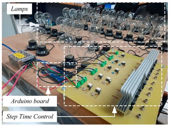
Figure 7.
Assembled step-resistant load battery simulator.
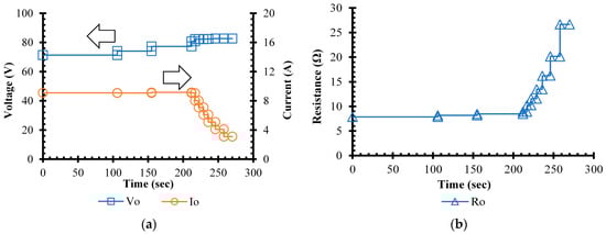
Figure 8.
Voltage, current and resistance characteristics of a golf cart 50 Ah 72 V Li-ion battery simulator. (a) Typical voltage and current characteristics. (b) Typical internal resistant characteristics. Directions of y-axes are indicated by arrows.
The experimental characteristics of a developed stepping-resistant Li-ion battery simulator, as shown in Figure 8, correspond to the realistic EV Li-ion battery, as shown in Figure 3, which we designed in Section 2.1.
3.2. IPT Coils Design
Using U-shaped EE55 ferrite cores, 80 strands of SWG 26 Litz wire were twisted to construct 30-turn coils in a helical pattern for the inductive coil design. For the U-shaped cores of the IPT, we used commercially available power supply ferrite cores with a 10 kHz frequency response, known as EE55. The EE55 core manufacturer advises that EE55 cores perform best at frequencies around 10 kHz for higher permeability and that cores with less permeability should not operate above 3 MHz. Due to the limitations of the silicon-based switches in the power inverter, we could only activate the IPT coils in our application between 50 kHz and 56 kHz. However, we organized the EE55 cores in four rows to accommodate this.
Figure 9a shows a model of the inductive coils. The coils’ magnetic simulation showed that the maximum magnetic intensity (H) and flux density (B) did not exceed the values suggested by the manufacturer. Before installation and charging for the realistic golf cart, as illustrated in Figure 9b, the IPT coils installed at (0, 0 and 60) mm were tested and evaluated for system performance.
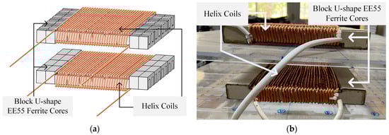
Figure 9.
Model and prototype of the IPT coils (a) Model of the helix coils on the U-shape EE55 ferrite cores. (b) A prototype of the inductive power transfer coils at (0, 0 and 60) mm.
The homemade twisted 80 SWG 31 of the Litz wire was designed for a 16 A high-frequency current that was disturbed by the skin effects. The Litz wire has more multistrands, causing lower AC resistance and lower heat loss at high frequencies in the inductive coils.
The core’s pole shoe length affects the core’s leakage flux, which limits the z-distance of the two coils. These relationships were proposed by [6].
The IPT coil’s AC resistance depends on the Litz wires’ multistrand number and sizing. Furthermore, the coil turns were specified by the values of L1, L2 and M. These parameters are dependent on the inductive coils’ physical dimensions. Conversely, the operating frequency is the independent parameter that engineers can select for the compromise system design. Then, the C1 and C2 of the series–series compensated circuit are the frequency-dependent parameters.
The coupling coefficient (k) and mutual inductance {M(X,Y,Z)}–distance characteristics, which were valid between the three dimensions of finite element programming and tested using the KEYSIGH E4980L RLC meter at the operating frequencies, are shown in Figure 10. The M and k were used in Equations (1), (2), (5) and (6) to evaluate the inductive coils’ output current, voltage, power and efficiency. The higher the X and Y axes’ misalignment, the lower the M because of the lower k of the Tx and Rx linkage. This evaluation proceeded according to the wireless power transfer design process published in [6].
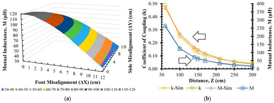
Figure 10.
Mutual inductance {M(X,Y,Z)}–z characteristics: (a) M–X,Y characteristics; (b) M and k–Z characteristics. Directions of y-axes are indicated by arrows.
3.3. Varied Frequency CC–CV Inverter Design
The varied frequency inverter structure is made of H-bridge switches. Indeed, the inverter’s switches were made of the silicon-based RGT00TS65D IGBT, where the F28379D MCU drove the gate signals via the TLP250 H optocouplers. The MCU was programmed through MATLAB/Simulink.
This prototype inverter’s switching frequencies, 50 kHz to 56 kHz, were lower than the 85 kHz range recommended by the IEC 61980-3 and the ANSI J2954 standards [47,48] due to the limitations of the silicon-based switches that were prepared in our laboratory.
The system parameters that we specified using the physical dimensions of the IPT coil design, the 42 kHz resonant frequency and the compensated capacitors are shown in Table 1.

Table 1.
Wireless charging system parameters.
Table 1 shows the inductive wireless charging system parameters, in which the Tx and Rx were installed at the (0, 0 and 60 mm) position.
The integration system consisted of an AC source, a single-phase front-end rectifier, the varied frequency H-bridge inverter, the inductive coils, the high-frequency rectifier, without and with the SS MEC converter, and the stepping-resistant battery simulator or the golf cart battery, as shown in Figure 11. The secondary-side high-frequency rectifiers consist of the ultrafast diode RURG8060. Moreover, the SS MEC buck converter consists of the RGT00TS65D IGBT switch and a silicon carbide diode rectifier, SCS230KE2.
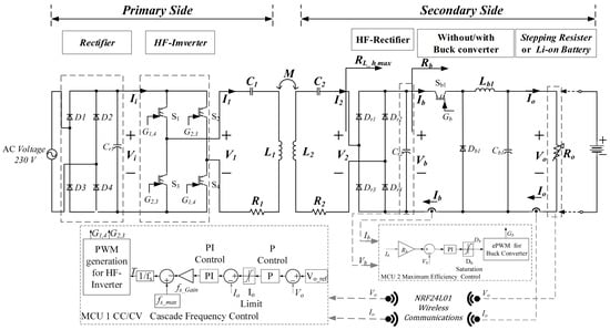
Figure 11.
System parameters of the varied frequency CC–CV inductive wireless EV charging.
In this regard, the DC input current (Ii) and DC input voltage (Vi) of the system shown in these figures can produce the DC input power (Pi). The DC output current (Io) and DC output voltage (Vo) are the system’s battery terminals’ DC output power. The battery’s current and voltage signals were fed back using the NRF24L01 wireless communication modules with a 25 ms delay time. These parameters are used for the system’s DC-to-DC efficiency calculation.
The high-frequency AC input current (I1), AC input voltage (V1), AC output current (I2) and AC output voltage (V2) are the IPT’s performance parameters.
The variable switching frequencies for the CC–CV charging for the step-resistant Li-ion battery simulator or the golf cart battery, as shown in Figure 12, were controlled by the MCU.
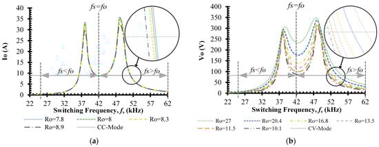
Figure 12.
Current- and voltage-frequency characteristics of the system at Vi of 311 Vdc: (a) current–frequency characteristics; (b) voltage–frequency characteristics.
The current- and voltage-frequency characteristics plots using Equations (1) and (2), when the Vi was 311 Vdc, are shown in Figure 12a,b. The frequency that achieved the CC 9 A charging current was in the range of around 52 kHz. The resonant inverter operated in the frequency range over the resonant frequency, as shown in Figure 12a. The constant charging voltage of CV 82 V was also accomplished between 52 kHz and 56 kHz, as shown in Figure 12b.
3.4. Simulation of Uncontrolled Charging
The uncontrolled or the open-loop varied frequency CC–CV inductive charging was simulated using MATLAB/Simulink. This stage’s objective was to evaluate the system’s input and output voltage and current values compared to the rated design values. Only the simulation of the uncontrolled operation was performed because the experiment of open-loop charging may have risks for overvoltage, overcurrent and system damage.
3.5. Simulation of Varied Frequency CC–CV Inductive Charging without and with the SS MEC Converter
Firstly, the varied frequency CC–CV inductive charging without the SS MEC converter simulation using MATLAB/Simulink was set up to evaluate the system performances of the CC–CV charging current and voltage, the system input current and the system’s efficiency. The feedback communication delay was assumed to be zero in these simulations. The voltage and current feedback signals from the wire communications were simulated.
Secondly, a simulation of the CC–CV charge using an SS MEC buck converter for an e-golf cart was verified in MATLAB/Simulink for tracking and maintaining the maximum point of the system’s efficiency during all load steps or SOC of the battery.
Thirdly, the system’s parameters and characteristics at misalignment positions between the Tx and Rx were simulated at (0, 0 and 60), (0, 90 and 60), (70, 0 and 60) and (70, 90 and 60) mm positioning, as shown in Figure 13.
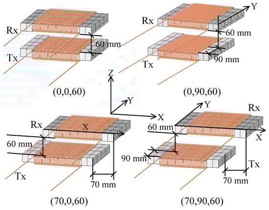
Figure 13.
Misalignment inductive coil conditions of the simulation for system characterizations.
3.6. Experiment of Varied Frequency CC–CV Charging without and with the SS MEC for the Step Load Battery Simulator
The prototype kits of the varied frequency CC–CV inductive charging without and with the maximum efficiency tracking SS converter were set up at the offset. Then, the test kits were tested for the step-load-resistant battery simulator to validate the CC–CV control system. Voltage and current sensors used wire communications to signal feedback for the first stage experiment in this study. The experiment setup is shown in Figure 14.
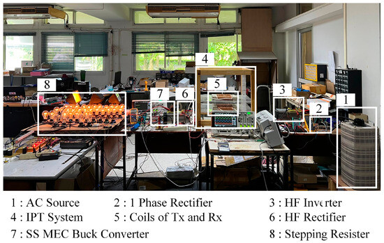
Figure 14.
Experiment setups of the prototype varied frequency inductive charging system.
In the experiment, the Tx and Rx were first positioned at the XYZ axis of (0, 0 and 60) mm. The system’s circuit parameters are shown in Table 1, and the CC–CV charging values setting was 9 A-82 V. Secondly, the three-phase rectified source of the 311 Vdc was to the primary inverter. Thirdly, the charging system charged for the 750 W stepping load, a controlled parameter shown in Figure 8b, using the Arduino Mega 2560 autonomously, comparing the charging conditions without and with the SS MEC converter. Then, the prototype system was applied for the 50 Ah 72 V e-golf cart Li-ion NMC battery in cases without and with the SS MEC converter to confirm the hypothesis of this study. Finally, the ratio between the DC input power (DC input current multiplied by the DC input voltage) and the DC output power (DC output current multiplied by the DC output voltage) was used to determine the efficiency of the wireless EV charging system. Additionally, the high-frequency current and voltage probes were used to measure the AC output power of the PS high-frequency inverter and the IPT coils, and an Agilent EQ-DSOX2024A, 200 MHz 4-channel oscilloscope was used to determine the AC output power. The oscilloscope’s math function calculated the averaged AC power by multiplying the system’s AC points’ instantaneous current and voltage values.
3.7. Experiment of Variable Frequency CC–CV Charging without and with the SS MEC for the e-Golf Cart Li-Ion Battery System
Firstly, a sample realistic 50 Ah 72 V Li-ion golf cart battery was charged using the offset prototype variable frequency CC–CV charging with the SS converter at Vi of 311 V plug-in from the 220 Vac 50 Hz system such as the Thailand utility. The system frequencies were much higher than the resonant frequency for higher input DC voltage.
Secondly, the sample battery was charged using the prototype at Vi of 155 V, which was the assumption for the plug-in from the 110 Vac 50 Hz, such as the Japan utility. In this case, the switching frequencies were slightly higher than the resonant frequency.
4. Results and Discussions
The results consist of (a) an uncontrolled charging simulation, (b) variable frequency CC–CV charging without and with the SS converter simulation, (c) an experiment on the step-resistant load battery simulator and (d) an experiment on the e-golf cart Li-ion battery system, as follows.
4.1. Uncontrolled Charging Simulation Results
The simulation results of the uncontrolled or the open loop are shown in Figure 15. The results show that when the system was a 311 V input voltage and 4.3 A input current, the battery charging current was 9.9 A, exceeding the CC mode set point for 9.0 A, and the CV mode of 82 V operated the charging voltage of 178.7 V. The overcurrent and overvoltage of the battery charging may damage the system’s components and the battery. This inductive wireless charging system needs the CC–CV controller, according to [21,23], which uses the primary buck converter.
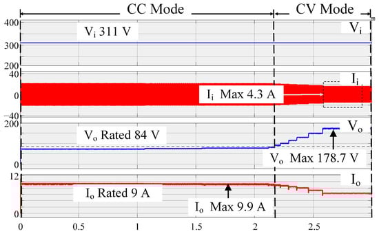
Figure 15.
Uncontrolled IPT charging simulation results.
4.2. The Wireless CC–CV Charging without and with the MEC at the Offset Simulation Results
The first target was the wireless CC–CV charging using the PS H-bridge inverter, which controls the switching frequencies to maintain the current and voltage for the battery. Then, the CC–CV charging system operation with the SS MEC converter to match the battery impedance to the IPT’s output impedance for maximum efficiency tracking was also an advantage that needed to be proved.
Firstly, the various frequency CC–CV charging using the primary-side H-bridge inverter was simulated using the system’s parameters of the offset (0, 0 and 60) mm position. The results found that when the input voltage was 311 V, the battery’s current and voltage input current were 3.26 A, 9.0 A and 82 V, as shown in Figure 16.
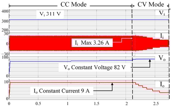
Figure 16.
Variable frequency CC–CV charging without the SS-MEC simulation results.
The varied frequency CC–CV inductive charger was better than the uncontrolled, as follows: (a) operated with a lower system input current (3.26 A); (b) maintained the constant 9.0 A charging current, the voltage not exceeding 84 V rated voltage of the battery in the CC mode, and the constant 82 V charging voltage in the CV mode.
This variable frequency CC–CV inductive wireless charging was valid for the study’s objective and the previous works [2,23].
Secondly, the feed-forward maximum efficiency regulated SS MEC converter, as shown in Section 2.4, was applied to the charger for validation by using the simulation. The simulation results found that for the same input voltage conditions, the input current was 2.89 A, 9.0 A and 82 V charging in the CC–CV mode, as shown in Figure 17.
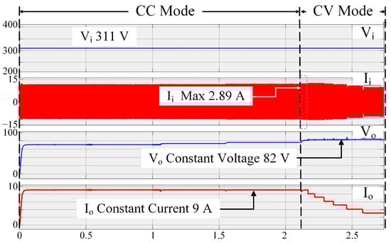
Figure 17.
Variable frequency CC–CV charging with the SS-MEC simulation results.
Using the SS converter reduced the maximum input current from 4.3 A in the uncontrolled experiment, 3.26 A in the case without the SS MEC converter, to 2.89 A, the best conditions in this study. The system’s losses depended on the system current, in that the higher the current, the higher the heat losses.
These results found that the CC–CV charging system operation with the SS MEC matched the battery impedance to the IPT’s output impedance, which trended to the maximum efficiency points.
Figure 18 shows the simulation outcomes of an uncontrolled variable frequency CC–CV inductive charger without and with an SS converter evaluated. Until the stepping time for switching from CC to CV mode, the uncontrolled system was charging at a lower power than the rated 750 W. The charging control was increased from 750 W to 1050 W with overcharging power and overvoltage. The variable frequency CC–CV inductive charger retained the charging power below the battery’s rated charging capacity, both without and with the SS MEC converter.
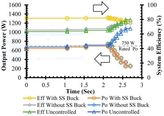
Figure 18.
Comparison of the output power and efficiency of inductive charging simulation results at the offset. Directions of y-axes are indicated by arrows.
In addition, although the uncontrolled charging systems’ efficiencies were 63% to 80%, but the overcurrent and overvoltage occurred. The varied frequency CC–CV inductive charger without the SS converter charged in the range of 65% to 75% efficiencies. The better efficiency conditions of the integration system with the SS converter charge for the CC–CV mode were in the range of 77% to 83%.
Moreover, the DC-to-DC efficiencies of the system at the misalignment positionings were simulated to evaluate the system’s performance and efficiency. The results found that the efficiencies of the system with the SS MEC at the XYZ (0, 0 and 60) mm position, k = 0.26, were in the range of 77% to 83% and higher than the range of 65% to 75% for the system without the SS MEC converter. That was the best position. On the other hand, at the worst misalignment position of XYZ (70, 90 and 60) mm, the k was decreased to 0.16. The efficiencies of the system without the SS MEC converter were in the range of 61% to 68%, significantly lower than the range of 65% to 74% of the system with the SS MEC converter, as shown in Figure 19.
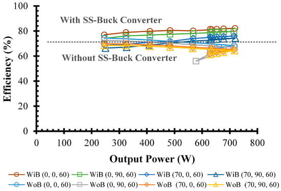
Figure 19.
Varied frequency CC–CV inductive charging with the SS-MEC simulation results.
The simulation was used to verify the CC–CV charging method employing variable frequency inductive battery charging and the SS MEC converter for optimal efficiency tracking.
4.3. The Wireless CC–CV Charging without and with the SS MEC for the Step Load Battery Simulator Experiment Results
Experiments on the varied frequency CC–CV inductive charge at the offset position were performed for the battery simulator.
Firstly, the inductive coils’ input and output voltage and current waveforms were compared, as shown in Figure 20. The input and output currents of the inductive coils when the system without the SS MEC converter, shown in Figure 20a, were higher than the system with it, as shown in Figure 20b. According to the simulation results, the SS MEC converter retained a lower system input current, as shown in Section 4.2.
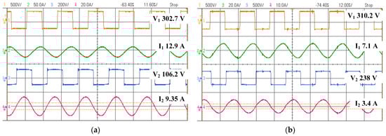
Figure 20.
Experimental input and output voltage and current waveforms of the inductive charger. (a) Input and output voltage and current of the inductive coils without the SS MEC converter. (b) Input and output voltage and current of the inductive coils with the SS converter.
According to earlier studies, the IPT coils’ sinusoidal input and output current waveforms and squared input and output voltage waveforms were all oriented toward the rectifier circuit, as shown in references [2,6,9,14,23].
Secondly, the varied frequency CC–CV inductive charger was applied for the battery simulator without the SS converter. The charging current was constant 9.0 A for CC mode, and the charging voltage was constant 82 V for the CV mode, as shown in Figure 21.
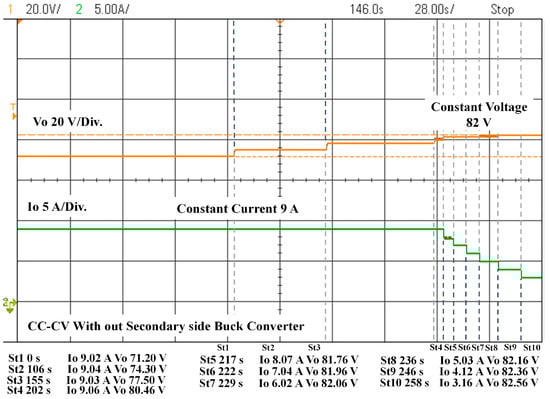
Figure 21.
Experimental CC–CV charging voltage and current of the system without the SS MEC converter.
According to the modeling results in Figure 16 and the actual data in Figure 21, the primary inverter’s switching frequency can be changed to implement the inductive CC–CV charging technique. According to [2,45], this supports using the CC–CV charging idea by altering the frequency of inductive coils.
Thirdly, the charging system with the SS MEC converter was experimented with, as shown in Figure 22. The results show that the system operated 9.0 A CC mode and 82 V CV mode. These confirmed that the varied frequency inductive wireless charging can be performed in the CC–CV mode in the cases without and with the SS MEC converter. Hence, the first objective of this study was demonstrated.
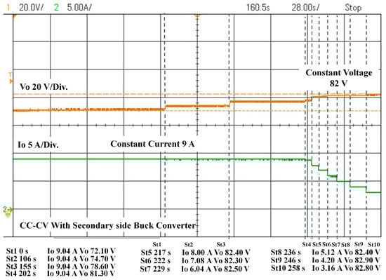
Figure 22.
Experimental CC–CV charging voltage and current of the system with the SS MEC converter.
According to Figure 23, the experimental results were examined for system power and efficiency. When using CC–CV charging at a variable frequency, both without and with an SS MEC converter, the charge power cannot be allowed to exceed the rated power. The system without the SS MEC converter had a charge efficiency of 64% to 70%, but the system with the SS MEC converter had higher efficiencies of 70% to 78%.
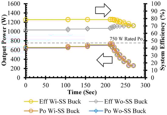
Figure 23.
Experimental power and efficiencies of the charging system without and with an SS MEC converter. Directions of y-axes are indicated by arrows.
In addition, the system without the SS MEC converter’s charging power varied from 641 W in the first step, maximized at 725 W at the fourth step (212 s) and minimized at 262 W at the tenth step. The system with the SS converter’s power was 625 W at the first step, maximized 735 W at the fourth step and minimized 262 W at the tenth step.
Moreover, without the SS MEC converter, the system’s efficiency was 64.5% at the first step, maximized at 69.8% at the seventh step and at 70.4% at the tenth step. On the other hand, using the SS MEC converter, the system’s efficiency was 74.8% at the first step. It maximized at 78.9% at the fourth step and minimized at 70.3% at the tenth step using the SS MEC converter to improve the system’s efficiency. However, the efficiency was reduced in the CV mode because the charging power decreased from 650 W to 260 W or 80% to 35% of the 750 W rated charging power. So, as the charging power remained low, the system’s efficiency declined.
The improvement in the system efficiency using the SS MEC converter was validated in the simulation, as shown in Figure 18, and the experiment, as shown in Figure 23. Nevertheless, the charging system’s efficiencies without and with the SS MEC were compared, as shown in Figure 24. So, the SS MEC kept the charging system’s efficiency higher than the charging system without it.
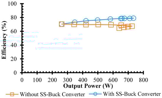
Figure 24.
Comparison of the experimental efficiencies without and with secondary-side converter. Directions of y-axes are indicated by arrows.
Because it fits the battery’s impedance with the inductive coils’ output impedance, as suggested in Section 2.4, the variable frequency CC–CV inductive charger operation with the SS MEC converter has increased the system’s efficiency.
4.4. Experimental Results of the Wireless CC–CV Charging without and with the SS MEC for the e-Golf Cart Li-Ion Battery System
Firstly, the prototype of the CC–CV charger with the SS MEC converter was used to charge a sample 50 Ah 72 V Li-ion golf cart battery when the DC input voltage Vi was 311 V, and the switching frequencies ranged from 45 kHz to 55 kHz, as shown in Figure 25 and Figure 26.
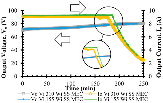
Figure 25.
CC–CV mode characteristics of the sample Li-ion battery at Vi 310 Vdc input. Directions of y-axes are indicated by arrows.
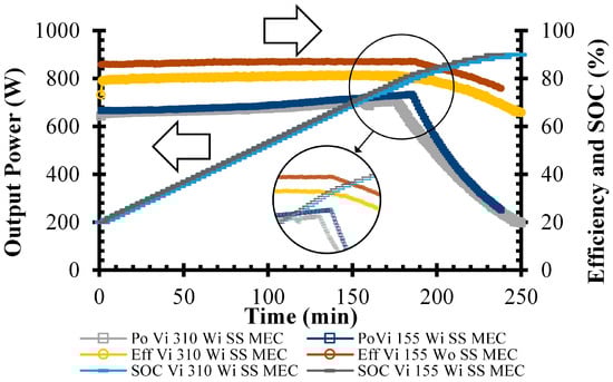
Figure 26.
Charging power, efficiency and SOC of the sample Li-ion battery at Vi 310 Vdc input. Directions of y-axes are indicated by arrows.
When the Vi was 311 V, the CC–CV characteristics of the sample Li-ion battery were operated at CC 9.0 A and CV 80 V for a 240 min charging time, as shown in Figure 25. The prototype variable frequency wireless EV charging operation was validated.
According to the SOC or battery resistance, as shown in Figure 26, the sample battery’s charge power varied between 200 W and 750 W. The sample battery’s SOC was directly influenced by the charge current in CC mode and slowly grew in CV mode. Furthermore, the DC-to-DC system efficiencies ranged from 78% to 87%.
The prototype system was also used in situations when the 155 Vdc input voltage, such as plugging in from a 110 Vac 50 Hz, was present. The exact CC–CV values were required for this experiment; hence, it was assumed using Equations (1) and (2) that the Vi would be reduced before the switching frequencies would be decreased close to the resonant frequency.
According to the findings, the 9.0 A CC and 80 V CV charging operations when Vi was 155 V, as illustrated in Figure 25, were verified with the same output as Vi’s 310 V. The 310 V of Vi was used to validate the same needed output while maintaining the power and SOC characteristics of the operations using the 115 V of Vi.
So, the prototype variable frequency CC–CV wireless charging system can be performed with the varied DC input voltage, Vi.
However, the e-golf cart Li-ion battery charging system’s DC-to-DC efficiencies of the prototype in the conditions of (a) 310 V of Vi input voltage and the system without the SS MEC converter (Vi 310 Wo SS MEC); (b) 310 V of Vi input voltage and the system with the SS MEC converter (Vi 310 Wi SS MEC) and 155 V of Vi input voltage and the system with the SS MEC converter (Vi 155 V Wi SS MEC) were compared as shown in Figure 26 and Figure 27. These confirmed that the prototype used for the sample e-golf cart battery charging with the SS MEC converter had a higher efficiency than the system without it.
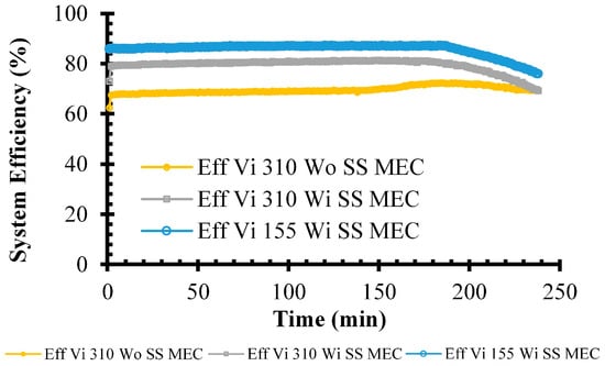
Figure 27.
Comparison of the experimental efficiencies without and with the secondary-side converter.
Nevertheless, the system in the conditions of 155 V of Vi input voltage and the system with the SS MEC converter (Vi 155 V Wi SS MEC) had higher efficiency because the switching frequencies operation range of 44 kHz to 46 kHz were close to the resonant frequency, 42 kHz. The switching frequencies were insignificantly higher than the resonant frequency (such as 44 kHz to 46 kHz) and were lower than the switching losses with the frequency much higher than the resonant frequency (such as 55 kHz to 65 kHz in the case of 310 V of Vi.) The range of the switching frequencies of the 155 V of Vi conditions is shown in Figure 28.
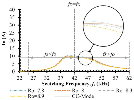
Figure 28.
Current–frequency characteristics of the system at Vi of 155 Vdc.
Actually, the difference between the input and output power values can be used to evaluate the power losses in various system components, including the HF inverter, IPT coils, HF-rectifier and SS buck converter. Therefore, the comparison of the losses between the variable frequency charging system without and with the SS MEC converter is shown in Figure 29. For the system without the SS MEC converter, the losses were divided between the main losses, due to the copper losses of the Litz wires of the IPT coils, and the switching losses of the inverter. The minor losses occurred in the heat losses of the rectifier, as shown in Figure 29a.
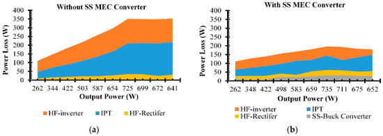
Figure 29.
Losses of the varied frequency CC–CV inductive charger. (a) Losses of the system without the SS MEC converter. (b) Losses of the system with the SS MEC converter.
The losses of the charging system with the SS MEC converter were lower than the others. Using the SS MEC converter, the losses were reduced by about half compared to the system without it. The SS MEC converter can decrease the IPT coil losses because the IPT coils’ impedance matches the battery impedance, as proposed in Equation (10), Section 2.4. Furthermore, the SS MEC converter abated the inverter losses because the input current of the inverter was reduced, as explained in Figure 16 and Figure 17. The lower input and output current inverter can decrease the switching losses in the inverter. The lower losses that the inductive wireless charging using the impedance matching regulator provided are shown in Figure 29b.
Also, the operating switching frequency, unimportantly more than the resonant frequency, kept the system efficiency higher.
In this study, the key elements of the varied frequency CC–CV inductive charger were examined. The efficiencies of the IPT charger were improved via (a) the secondary-side maximum efficiency control (SS MEC) converter, according to Equation (10), and (b) the input voltage reduction to achieve the inverter’s switching frequency range near the resonant frequency. The experiments were validated on the Li-ion battery golf cart charging.
Table 2 shows the state-of-the-art IPT wireless EV charging and the novel technique presented in this paper. The IPT chargers need CC–CV charging control using the primary buck converter [21,23,43]. For this study, we proposed the varied frequency of the primary inverter to control the CC–CV charging according to [35,44,45]. The system output impedance could match the battery’s internal resistance to maintain the maximum conditions derived in Equations (9)–(12), validated using the simulations and experiments using the SS MEC converter. In this paper, a novel technique for controlling wireless EV charging via wired communications with a 25 ms latency and maximum efficiency point tracking using an SS MEC converter was put forth.
Table 2.
Comparison of the wireless charging.
This contribution can maintain the maximum efficiency point during the wireless EV charging validation by the simulations and experiments for the stepping resistance load and the 50 Ah 72 V Li-ion NMC battery unit. Indeed, the variable frequency CC–CV charging using the PS inverter advantage for wireless EV charging does not need the PS buck converter or equivalents that cause losses in the PS buck converter. In addition, the operating varied frequencies of the wireless EV charging close to the system resonant frequency retain lower switching losses in the PS inverter, as shown in Section 4.4. The 115 V conditions were more efficient than the 311 V conditions. Moreover, the maximum efficiency points can be tracked using the SS MEC converter, and lower system losses occur in these conditions due to the inadequate system input current. Although this study maintains the system efficiency tracking in the best range of 76% to 87%, the system efficiency may improve for the higher than 750 W charging power. The lower the output power, the lower the efficiency of the power electronics system.
For future work, the CC–CV varied frequency wireless EV charging needs the operating frequency close to the IPT circuit resonant frequency, which means the resonant frequency must also vary. For this case, the variable resonant frequency of the IPT compensation networks, such as the S-S circuit in [21,23,43], LCL-LCL circuit [35] and LCC-LCC circuit [45], need to be redesigned. The variable capacitance and inductance devices are necessary for this technique for the new paradigm. Also, the lower Litz wire’s resistance is the base demand for the coil design stage. Additionally, the high-frequency converters for wireless EV charging require switches with Si-C technology.
Therefore, this study’s merits have validated the variable frequency CC–CV charging and MEC techniques. Also, this gained experience improves the competitive ability to develop the wireless EV charging system for industrial and university sectors, provides a Thai perspective on EV applications and technology and prepares knowledge for Thailand’s light EV industry. Nevertheless, this study intended to improve the technology readiness level (TRL) from TRL 4—the key element demonstrated in a laboratory environment [2,23] to TRL 5—the key element demonstrated in relevant environments supported by the Energy Policy and Planning Office (EPPO) and the National Research Council of Thailand (NRCT).
5. Conclusions
In this paper, the IPT is applied to the CC–CV wireless inductive charger to the golf cart Li-ion battery using the variable frequency control primary inverter that does not need the PS buck converter. The IPT coils were made of EE55 ferrite cores and twisted by the 80 strains of the SWG 26 for 30 turns each Tx and Rx. The M and k parameters of the two coils were simulated and tested at the XYZ (0, 0 and 60) mm for the best linkage position and the XYZ (70, 90 and 60) mm for the worst linkage. For the 50 Ah 72 V Li-ion battery system, the system resonant frequency was 42 kHz, which was conditioned using the series–series compensation circuits using capacitors.
Moreover, comparing the secondary-side control using a buck converter to match the IPT’s output impedance and the battery’s resistance to regulate the maximum efficiency points of the wireless charging system is proposed. The MATLAB/Simulink simulation examined the prototype wireless inductive charging system in conditions of the:
- (a)
- CC–CV varied frequency charging with un-control;
- (b)
- CC–CV varied frequency charging without the SS MEC converter; and
- (c)
- CC–CV varied frequency charging with the SS MEC converter, tested for the stepping-resistant load battery simulator and tested for the Li-ion NMC battery.
The results found that the simulation and the experiment were in accordance. The charging system performs CC 9 A, CV 80 and V 730 W for the 50 Ah 72 V Li-ion battery system. In the 311 V DC input voltage condition, where the operating frequencies were in the range of 55 kHz to 65 kHz, the system’s efficiency was 62% to 72% without the SS MEC converter. The system with the matching impedance SS MEC converter had 65% to 81% efficiency. So, the maximum efficiency can be regulated using the SS MEC converter.
The best conditions occurred in the 155 V DC input voltage cases. The operating frequencies ranged from 44 kHz to 46 kHz, and the system with the SS MEC converter had 76% to 87% efficiency. This work also verified that the operating frequencies close to the resonant frequency reached higher efficiency because of the lower switching losses.
This study showed that the varied frequency CC–CV wireless EV charging system needs to vary the resonant frequency of the IPT system. The wireless EV charging system’s variable capacitance and inductance devices have to be developed soon.
Author Contributions
Conceptualization, J.T., U.K. and A.N.; methodology, J.T., U.K., A.N., T.S., E.C., S.J., S.Y. and C.K.; Data curation, T.S. and E.C.; writing—original draft preparation, J.T., U.K. and A.N.; writing—review and editing, J.T., U.K., A.N., P.T. and N.T.; visualization, T.S., S.Y. and C.K.; supervision, P.T. and N.T.; project administration, P.T. All authors have read and agreed to the published version of the manuscript.
Funding
This research was funded by the National Research Council of Thailand (NRCT) under the Senior Research Scholar Program, the project entitled Modern DC Microgrid Applications for Thailand Sustainable Development, grant number N42A640328. Additionally, this study was funded by the Rajanamgala University of Technology Lanna (RMUTL) under the project entitled Innovational Development of Inductive Wireless EV Charging Station for the Commercial EV in Thailand, grant number RMUTL 2566FF060 (FRB660059/0171), dated 1 October 2022.
Data Availability Statement
Not applicable.
Acknowledgments
This work was supported in part by an International Research Partnership “Electrical Engineering—Thai French Research Center (EE-TFRC)” under the project framework of the Lorraine Université d’Excellence (LUE) in cooperation with Université de Lorraine and King Mongkut’s University of Technology North Bangkok and in part by the National Research Council of Thailand (NRCT) under the Senior Research Scholar Program under Grant No. N42A640328.
Conflicts of Interest
The authors declare no conflict of interest.
References
- Deng, F.; Zhang, Y.; Liu, Q.; Xie, J.; Wang, J. Analysis on Wireless Charging Technology of Electric Vehicle. J. Phys. Conf. Ser. 2021, 1876, 012017. [Google Scholar] [CrossRef]
- Sriprom, T.; Namin, A.; Tammawan, W.; Yachiangkam, S.; Janjommanit, S.; Kamnarn, U.; Thongpron, J.; Karnjanapiboon, C.; Thounthong, P.; Takorabet, N. Variable Frequency Control for Constant Current Constant Voltage Inductive Wireless EV Charging System. In Proceedings of the 2022 International Power Electronics Conference (IPEC-Himeji 2022- ECCE Asia), Himeji, Japan, 15–19 May 2022; pp. 1481–1488. [Google Scholar]
- IEA. Global EV Outlook 2022; IEA: Paris, France, 2022; pp. 3–14. [Google Scholar]
- IEA. Securing Clean Energy Technology Supply Chains; IEA: Paris, France, 2022; p. 4. [Google Scholar]
- Welch, D. Inflation Turns EVs Into Luxury Item Threatening Broader Electric Shift. Bloomberg. Available online: https://www.bloomberg.com/news/articles/2022-06-17/inflation-turns-evs-into-luxury-items-threatening-broader-electric-shift (accessed on 13 August 2022).
- Thongpron, J.; Tammawan, W.; Somsak, T.; Tippachon, W.; Oranpiroj, K.; Chaidee, E.; Namin, A. A 10 kW Inductive Wireless Power Transfer Prototype for EV Charging in Thailand. ECTI-EEC 2022, 20, 83–95. [Google Scholar] [CrossRef]
- Kusaka, K.; Kusui, R.; Itoh, J.I.; Sato, D.; Shijo, T.; Obayashi, S.; Ishida, M. A 22kW Three-phase Wireless Power Transfer System in Compliance with CISPR 11 and ICNIRP 2010. IEEJ J. Ind. Appl. J-SRAGE Adv. Publ. 2022, 11, 594–602. [Google Scholar] [CrossRef]
- Imura, T.; Suzuki, K.; Hata, K.; Hori, Y. Comparison of Four Resonant Topologies Based on Unified Design Procedure for Capacitive Power Transfer. IEEJ J. Ind. Appl. 2021, 10, 339–347. [Google Scholar] [CrossRef]
- Namin, A.; Chaidee, E.; Tanang, S.; Chaikam, K.; Jansuya, P. Mutual Impedance Adaptation for Maximum Power Point Tracking on LED TV Wireless Power Transfer Vary with Distance. In Proceedings of the 2018 15th International Conference on Electrical Engineering/Electronics, Computer, Telecommunications and Information Technology (ECTI-CON), Chiang Rai, Thailand, 18–21 July 2018; pp. 501–504. [Google Scholar]
- Supapong, N.; Sangswang, N.; Naetiladdanon, S.; Mujjalinvimut, E. A Novel Output Power Control of Wireless Powering Kitchen Appliance System with Free-Positioning Feature. Energies 2018, 11, 1671. [Google Scholar]
- Khan-ngern, W.; Zenkner, H. Wireless power charging on electric vehicles. In Proceedings of the 2014 International Electrical Engineering Congress (iEECON), Chonburi, Thailand, 19–21 March 2014; pp. 1–4. [Google Scholar]
- Nalinnopphakhun, P.; Onreabroy, W.; Kaewpradap, A. Parameter Effects on Induction Coil Transmitter of Wireless Charging System for Small Electric Motorcycle. In Proceedings of the 2018 IEEE International WIE Conference on Electrical and Computer Engineering (WIECON-ECE), Chonburi, Thailand, 14–16 December 2018; pp. 145–148. [Google Scholar]
- Jeebklum, P.; Aodsup, K.; Sumpavakup, C. Development of a Static Wireless Power Transfer System for Electric Bikes. In Proceedings of the 2019 Research, Invention, and Innovation Congress (RI2C), Bangkok, Thailand, 11–13 December 2019; pp. 1–4. [Google Scholar]
- Namin, A.; Chaidee, E.; Prachuabroek, T.; Jumpoo, T.; Thamapanya, N. Solar Tricycle with Lateral Misalignment Maximum Power Point Tracking Wireless Power Transfer. In Proceedings of the 2018 15th International Conference on Electrical Engineering/Electronics Computer Telecommunications and Information Technology (ECTI-CON), Chiang Rai, Thailand, 18–21 July 2018; pp. 656–659. [Google Scholar]
- Jiang, Y.; Wang, L.; Wang, Y.; Liu, J.; Wu, M.; Ning, G. Analysis, Design, and Implementation of WPT System for EV’s Battery Charging Based on Optimal Operation Frequency Range. IEEE Trans. Power Electron. 2019, 34, 6890–6905. [Google Scholar] [CrossRef]
- Hatchavanich, N.; Konghirun, M.; Saengswang, A. LCL—LCCL Voltage Source Inverter with Phase Shift Control for Wireless EV Charger. In Proceedings of the IEEE 12th PEDS Conference 2017, Honolulu, HI, USA, 12–15 December 2017; pp. 297–301. [Google Scholar]
- Rittiplang, A.; Pijitrojana, W.; Daroj, K. Low frequency wireless power transfer using modified parallel resonance matching at a complex load. KKU Eng. J. 2016, 43, 184–188. [Google Scholar]
- Amasiri, W.; Pothong, P.; Pinyathanabat, T.; Pijitrojana, W. Automatic Efficiency Maintaining System for Wireless Power Transfer Using Automatic Resonance Frequency. Thammasat Sci. Technol. J. 2017, 25, 870–879. [Google Scholar]
- Namin, A.; Chaidee, E.; Sriprom, T.; Bencha, P. Performance of Inductive Wireless Power Transfer Between Using Pure Sine Wave and Square Wave Inverters. In Proceedings of the 2018 IEEE Transportation Electrification Conference and Expo, Asia-Pacific (ITEC Asia-Pacific), Bangkok, Thailand, 6–9 June 2018; pp. 1–5. [Google Scholar]
- Vienglek, P.; Nutwong, S.; Sangswang, A.; Naetiladdanon, S.; Mujjalinvimut, E. Comparative Study of Magnetically Coupled Coil Used in Dynamic Wireless Battery Charger for Electric Vehicles. In Proceedings of the 2020 23rd International Conference on Electrical Machines and Systems (ICEMS), Hamamatsu, Japan, 24–27 November 2020; pp. 1775–1778. [Google Scholar]
- Kim, H.; Song, C.; Kim, D.H.; Jung, D.H.; Kim, I.M.; Kim, Y.I.; Kim, J.; Ahn, S.; Kim, J. Coil Design and Measurements of Automotive Magnetic Resonant Wireless Charging System for High-Efficiency and Low Magnetic Field Leakage. IEEE Trans. Microw. Theory Tech. 2016, 64, 383–400. [Google Scholar] [CrossRef]
- Afshin, M.; Rathore, A.K. Receiver Side Control for Efficient Inductive Power Transfer for Vehicle Recharging. In Proceedings of the 2017 IEEE Transportation Electrification Conference (ITEC-India), Pune, India, 13–15 December 2017; pp. 1–6. [Google Scholar]
- Yachiangkam, S.; Tammawan, W.; Sriprom, T.; Thongpron, J.; Kamnarn, U.; Oranpiroj, K.; Somsak, T.; Yotkaew, E.; Namin, A. Wireless Golf Cart Charging Development in Thailand 2022. In Proceedings of the International Electrical Engineering Congress (IEECON), Khon Kaen, Thailand, 9–11 March 2022; pp. 1–4. [Google Scholar]
- EVAT. Electric Tuk Tuk Conversion. Electric Vehicle Association of Thailand (EVAT). Available online: https://www.evat.or.th/16927808/electric-tuk-tuk-conversion (accessed on 13 August 2022).
- Liu, J.; Deng, Q.; Wang, W.; Li, Z. Modeling and Control of Inverter Zero-Voltage-Switching for Inductive Power Transfer System. IEEE Access 2019, 7, 139885–139894. [Google Scholar] [CrossRef]
- Zhu, H.; Zhang, B.; Wu, L. Output Power Stabilization for Wireless Power Transfer System Employing Primary-Side-Only Control. IEEE Access 2020, 8, 63735–63747. [Google Scholar] [CrossRef]
- Song, K.; Li, Z.; Jiang, J.; Zhu, C. Constant Current/Voltage Charging Operation for Series–Series and Series–Parallel Compensated Wireless Power Transfer Systems Employing Primary-Side Controller. IEEE Trans. Power Electron. 2018, 33, 8065–8080. [Google Scholar] [CrossRef]
- Chen, C.; Zhou, H.; Deng, Q.; Hu, W.; Yu, Y.; Lu, X.; Lai, J. Modeling and Decoupled Control of Inductive Power Transfer to Implement Constant Current/Voltage Charging and ZVS Operating for Electric Vehicles. IEEE Access 2018, 6, 59917–59928. [Google Scholar] [CrossRef]
- Liu, Y.; Feng, H. Maximum Efficiency Tracking Control Method for WPT System Based on Dynamic Coupling Coefficient Identification and Impedance Matching Network. IEEE J. Emerg. Sel. Top. Power Electron. 2020, 8, 3633–3643. [Google Scholar] [CrossRef]
- Liu, F.; Chen, K.; Zhao, Z.; Li, K.; Yuan, L. Transmitter-Side Control of Both the CC and CV Modes for the Wireless EV Charging System With the Weak Communication. IEEE J. Emerg. Sel. Top. Power Electron. 2018, 6, 955–965. [Google Scholar] [CrossRef]
- Lee, S.-W.; Choi, Y.-G.; Kim, J.-H.; Kang, B. Wireless Battery Charging Circuit Using Load Estimation without Wireless Communication. Energies 2019, 12, 4489. [Google Scholar] [CrossRef]
- Zhu, X.; Zhao, X.; Li, Y.; Liu, S.; Yang, H.; Tian, J.; Hu, J.; Mai, R.; He, Z. High-efficiency WPT System for CC/CV Charging Based on Double-half-bridge Inverter Topology with Variable Inductors. IEEE Trans. Power Electron. 2022, 37, 2437–2448. [Google Scholar] [CrossRef]
- Li, Y.; Liu, S.; Zhu, X.; Hu, J.; Zhang, M.; Mai, R.; He, Z. Extension of ZVS Region of Series–Series WPT Systems by an Auxiliary Variable Inductor for Improving Efficiency. IEEE Trans. Power Electron. 2021, 36, 7513–7525. [Google Scholar] [CrossRef]
- Wu, L.; Zhang, B.; Jiang, Y. Position-Independent Constant Current or Constant Voltage Wireless Electric Vehicles Charging System Without Dual-Side Communication and DC–DC Converter. IEEE Trans. Ind. Electron. 2022, 69, 7930–7939. [Google Scholar] [CrossRef]
- Zhang, M.; Tan, L.; Li, J.; Huang, X. The Charging Control and Efficiency Optimization Strategy for WPT System Based on Secondary Side Controllable Rectifier. IEEE Access 2020, 8, 127993–128004. [Google Scholar] [CrossRef]
- Yue, R.; Wang, C.; Li, H.; Liu, Y. Constant-Voltage and Constant-Current Output Using P-CLCL Compensation Circuit for Single-Switch Inductive Power Transfer. IEEE Trans. Power Electron. 2021, 36, 5181–5190. [Google Scholar] [CrossRef]
- Ota, R.; Nugroho, D.S.; Hoshi, N. Efficiency Maximization of Inductive Power Transfer System by Impedance and Switching Frequency Control in Secondary-side Converter. In Proceedings of the 2018 International Power Electronics Conference (IPEC-Niigata 2018-ECCE Asia), Niigata, Japan, 20–24 May 2018; pp. 3855–3862. [Google Scholar]
- Matsumoto, R.; Fujimoto, H. Adaptive Compensation Scheme for Wireless Power Transfer Systems with Coil Inductance Variation Using PWM-Controlled Switched Capacitor. In Proceedings of the Wireless Power Week (WPW), Bordeaux, France, 5–8 July 2022; pp. 244–248. [Google Scholar]
- Li, Y.; Hu, J.; Chen, F.; Li, Z.; He, Z.; Mai, R. Dual-Phase-Shift Control Scheme With Current-Stress and Efficiency Optimization for Wireless Power Transfer Systems. IEEE Trans. Circuits Syst. 2018, 65, 3110–3121. [Google Scholar] [CrossRef]
- Xu, S.; Jiang, W.; Hashimoto, S. Analysis and Design of an Air-Coupled DC Transformer with a Hybrid Modulation Control Method. Energies 2019, 12, 2570. [Google Scholar] [CrossRef]
- Mai, R.; Liu, Y.; Li, Y.; Yue, P.; Cao, G.; He, Z. An Active-Rectifier-Based Maximum Efficiency Tracking Method Using an Additional Measurement Coil for Wireless Power Transfer. IEEE Trans. Power Electron. 2018, 33, 716–728. [Google Scholar] [CrossRef]
- Zhao, Q.; Wang, A.; Liu, J.; Wang, X. The Load Estimation and Power Tracking Integrated Control Strategy for Dual-Sides Controlled LCC Compensated Wireless Charging System. IEEE Access 2019, 7, 75749–75761. [Google Scholar] [CrossRef]
- Iam, I.W.; Hoi, I.U.; Huang, Z.; Gong, C.; Lam, C.S.; Mak, P.I.; Martins, R.P.D.S. Constant-Frequency and Noncommunication-Based Inductive Power Transfer Converter for Battery Charging. IEEE J. Emerg. Sel. Top. Power Electron. 2022, 10, 2147–2162. [Google Scholar] [CrossRef]
- Yue, K.; Zhong, W.; Xu, D. A Frequency Tuning Series-Series WPT System with Wide Coupling and Load Ranges. In Proceedings of the IEEE 1st International Power Electronics and Application Symposium (PEAS), Shanghai, China, 13–15 November 2021; pp. 1–6. [Google Scholar]
- Van-Binh, V.; Van-Tuan, D.; Van-Long, P.; Woojin, C. A new method to implement the constant Current-Constant Voltage charge of the Inductive Power Transfer system for Electric Vehicle applications. In Proceedings of the 2016 IEEE Transportation Electrification Conference and Expo Asia-Pacific (ITEC Asia-Pacific), Busan, Republic of Korea, 1–4 June 2016; pp. 449–453. [Google Scholar]
- IEC 61980-1: 2020; Electric Vehicle Wireless Power Transfer (WPT) Systems-Part 1: General Requirement. IEC Standards: Paris, France, 2020; 88p.
- IEC 61980-3: 2022; Electric Vehicle Wireless Power Transfer (WPT) Systems-Part 3: Specific Requirement for Magnetic Field Wireless Power Transfer Systems. IEC Standards: Paris, France, 2022; 239p.
- SAE J2954-2016; Wireless Power Transfer for Light Duty Plug-in/ Electric Vehicles and Alignment Methodology. SAE International: Warrendale, PA, USA, 2016; 115p.
- Aditya, K.; Williamson, S. Linearization and Control of Series-Series Compensated Inductive Power Transfer System Based on Extended Describing Function Concept. Energies 2016, 9, 962. [Google Scholar] [CrossRef]
- Chen, P.-H.; Li, C.; Dong, Z.; Priestley, M. Inductive Power Transfer Battery Charger with IR-Based Closed-Loop Control. Energies 2022, 15, 8319. [Google Scholar] [CrossRef]
Disclaimer/Publisher’s Note: The statements, opinions and data contained in all publications are solely those of the individual author(s) and contributor(s) and not of MDPI and/or the editor(s). MDPI and/or the editor(s) disclaim responsibility for any injury to people or property resulting from any ideas, methods, instructions or products referred to in the content. |
© 2023 by the authors. Licensee MDPI, Basel, Switzerland. This article is an open access article distributed under the terms and conditions of the Creative Commons Attribution (CC BY) license (https://creativecommons.org/licenses/by/4.0/).