Article

The Impact of Full-System Decontamination of Kori Unit 1 on the Radioactive Waste Classification of Steam Generator Tubes

Department of NPP Engineering, KEPCO International Nuclear Graduate School, 658-91 Haemaji-ro, Seosaeng-myeon, Ulju-gun, Ulsan 45014, Republic of Korea
*
Author to whom correspondence should be addressed.
Energies 2023, 16(15), 5787; https://doi.org/10.3390/en16155787
Submission received: 20 June 2023 / Revised: 26 July 2023 / Accepted: 2 August 2023 / Published: 3 August 2023
(This article belongs to the Special Issue The Future of Nuclear Power for Clean Energy Systems)

Abstract

:
Kori Unit 1, which was permanently shut down on 18 June 2017, is planned to undergo full-system decontamination prior to major decommissioning activities. One of the advantages of performing FSD is the downgrading of the classification level of radioactive waste. From this perspective, the impact on the steam generator (SG) tubes, which account for a considerable portion of the total surface area during FSD operation, was examined. Initially, the CRUDTRAN code was used to predict the radioactivity inventory of the Kori Unit 1 SG tubes, which turned out to be approximately 21% more conservative than the measured value. To estimate the radioactivity in the tubes after FSD, decontamination factor values from overseas cases in the SG tubes section were selected and applied. Then, the regulations for radioactive waste in Korea were reviewed, and the specific activity was calculated by predicting the mass of the SG tubes. As a conclusion, it was confirmed that the SG tubes will be classified as low-level radioactive waste, whether FSD is performed or not. Furthermore, it was observed that even if a high efficiency of FSD is achieved, if stored, it would take more than 50 years for clearance.

1. Introduction

Full-system decontamination (FSD) is a technology that employs specialized decontamination chemicals to eliminate radioactive materials clinging to the inner surfaces of equipment and pipes in the primary system during the transitional phase following a permanent shutdown of a nuclear power plant (NPP). The advantages of performing FSD include decreasing the radiological exposure for workers involved in the decommissioning process, preventing the spread of radioactive contamination, and downgrading the level of classification of radioactive waste.
Kori Unit 1, a WH two-loop pressurized water reactor (PWR), which was permanently shut down on 18 June 2017 in Korea, is planning a system decontamination project. Korea Hydro & Nuclear Power (KHNP) and KEPCO Engineering & Construction (KEPCO E&C) are presently executing the detailed design of the Chemical Injection and Decomposition & Treatment Facility (CIDF). It is a commercial facility for system decontamination that will implement the CRI_RWDecom (Chemical Reagent Injection and RadWaste Decomposition & Treatment) technology, a system decontamination method developed by KHNP. The FSD scope for Kori Unit 1 encompasses the entire primary system, including the reactor coolant system (RCS), chemical and volume control system (CVCS), and residual heat removal system (RHRS) [1].
FSD generates a substantial amount of secondary waste, and managing and disposing of this waste presents challenges. In particular, the FSD efficiency of SG tubes, which account for approximately 80% of the total surface area during the FSD operation [2], is associated with various conflicting opinions related to the subsequent disposal of SG tubes, handling of secondary waste, costs, and other relevant issues. To address these issues, firstly, this study aims to estimate the radioactive inventory in the steam generator (SG) tubes. The research also seeks to assess the impact of FSD on downgrading the classification level of radioactive waste in the tubes.

2. Background

2.1. CRUD

CRUD (chalk river unidentified deposit) refers to the corrosion products that form because of the corrosion of structural materials (e.g., nickel alloy for SG tubes, zirconium alloy for fuel cladding, stainless steel for piping) in NPPs. CRUD floats in the coolant or settles on RCS lines. The CRUD mainly consists of nickel ferrite (NiFe2O4), magnetite (Fe3O4), and nickel oxide (NiO), with some components such as zirconium dioxide (ZrO2), Cr, Zn, Si, and others.
The presence of CRUD on fuel surfaces can have significant consequences, including disruptions in the core neutron flux. This phenomenon is known as an axial offset anomaly (AOA) or CRUD-induced power shift (CIPS). Nuclear power plants that exceed acceptable limits for AOA or CIPS may be required to reduce power output or even shut down operations to maintain safety standards [3].
CRUD is formed as it circulates through the coolant, interacting with neutrons and becoming radioactive. The sequential substitution of materials with CRUD in the coolant leads to high radioactivity. The radioactive sources primarily emit gamma radiation and include nuclides such as 58Co, 60Co, 137Cs, 55Fe, and 54Mn. The characteristics of the major radioactive corrosion products are summarized in Table 1. 58Ni and 59Co ions and oxides leaching from the primary system surfaces are transported into the reactor core, where they undergo neutron reactions and are converted to 58Co and 60Co, respectively.

2.2. Full-System Decontamination (FSD)

Generally, decontamination is carried out to minimize radiation exposure to both workers and the public. Unlike decontamination during operation, decontamination during NPP decommissioning removes as much radioactive material as possible while allowing some damage to the base material and achieving a high decontamination factor (DF) to ensure that waste disposal meets targeting levels. The DF is defined by the following equation.
DF = C o n t a m i n a t i o n   l e v e l   o f   s u b s t r a t e   b e f o r e   t h e   d e c o n t a m i n a t i o n C o n t a m i n a t i o n   l e v e l   o f   s u b s t r a t e   a f t e r   t h e   d e c o n t a m i n a t i o n
According to Table 2, which presents typical contamination statuses based on surface depth and the DF after layers are removed, the primary structural surfaces within the primary coolant system of a pressurized water reactor (PWR) are typically covered by layers of oxide films composed of metal oxides, such as iron, nickel, and chromium.
To effectively remove these contaminated layers, a sequential application of oxidation and reduction processes, known as FSD, is necessary. Notable FSD processes employed in the decommissioning of commercial NPPs include chemical oxidation reduction decontamination (CORD) in France and decontamination for decommissioning (DfD) in the U.S.

3. Prediction of Radioactive Inventory of SG Tube before FSD

While several programs have been developed or are under development worldwide to predict corrosion products and radioactive nuclide inventories during the design phase, there is currently a lack of specific programs to accurately assess the quantity of corrosion products and radioactivity originating from CRUD for nuclear decommissioning. In this study, the CRUDTRAN program will be utilized to evaluate the amount of CRUD and cobalt radioactive nuclides in the primary coolant system, enabling the prediction of radioactivity inventory in the SG tubes.

3.1. CRUDTRAN

The CRUDTRAN code is an empirical code designed to simulate the movement of soluble and particulate corrosion products, specifically iron, nickel, and cobalt. It incorporates balance equations to account for the dissolution of ions in the SGs and their deposition on in-core areas. The code also considers particle nucleation in the core regions, particle breakdown in the SGs, and in-core precipitation and out-core release of dissolved materials. Notably, the formation of radionuclides such as 58Co and 60Co in structural materials within the core is modeled, followed by their release into the coolant and deposition on out-core surfaces. The values used in CRUDTRAN were derived from data collected from the PWR coolant chemistry loop at the Massachusetts Institute of Technology (MIT). Activity transport depends on the dissolution rate of corrosion films on the wetted surfaces of the primary coolant system. Additionally, CRUDTRAN accounts for the sensitivity of corrosion to radiation levels in the core region and is based on simple physical observations [6,7].

3.1.1. Input Data

For the execution of the CRUDTRAN code, input data are required, as outlined in Table 3, consisting of a total of 50 factors in 11 groups. These data can be classified into two categories: the input data obtained from the field and the input data obtained through experimental and numerical methods. In this study, the input data were constructed based on the water chemistry data and other data related to the primary system of Kori Unit 1. For the unavailable input data, numerical values from CRUAS Unit 1 in France were cited.
The actual work for the replacement of the SGs in Kori Unit 1 was conducted over a total of 68 days, from 20 June to 26 August 1998, which was within the overhaul period of the 17th cycle. Since the purpose of this study was to predict the radioactivity of the replaced steam generator, only the cycles after the SG replacement were considered. The cycles are summarized in Table 4, and the operation and maintenance dates for the 17 cycles up to permanent shutdown were calculated by averaging for the ease of composing the input text for the CRUTRAN code. Therefore, the average number of operation days was rounded up to 352 days, and the average number of maintenance days was rounded down to 54 days. However, to keep the total number of days consistent, the average number of maintenance days of the cycles from the first to the twelfth was incremented by 1 day to 55 days.
Within one cycle, variables that change depending on the operation stage include the concentration of boron, the concentration of LiOH, the flow rate, and the temperature at the inlet and outlet of the core [8]. These are presented in Table 5. Additionally, it is assumed that the core output is at 100% and fuel is reloaded on the last day of the maintenance period.

3.1.2. Evaluation Results

The calculation results from CRUDTRAN provide the amount of CRUD in the SGs and core, the surface radioactivity of the radioactive nuclides 58Co and 60Co in the SGs and core, and the radioactive concentration in the coolant. The results based on the above input data are presented in Table 6. The CRUDTRAN calculation was conducted on 11 August 2017, which considered the 54-day maintenance period from 18 June 2017.

3.2. Radioactive Inventory

The SG values among the evaluation results from CRUDTRAN in Table 6 are specific to the tubes [6]. Therefore, it was calculated based on the heat transfer area of one steam generator, which is about 5119 m2. Considering this, by using the values of 60Co S/G and 58Co S/G from the CRUDTRAN code results in Table 6, the radioactivity in the SG tubes can be predicted as 8.07 × 10¹² Bq from 58Co and 1.19 × 10¹³ Bq from 60Co, respectively. It can be inferred that the total radioactivity inventory in the SG tubes of Kori Unit 1 immediately after the permanent shutdown on 11 August 2017 was approximately 1.99 × 10¹³ Bq, as shown in Table 7.
However, it is important to note that these values are derived from modeling and estimations and may deviate from actual measurements. Factors such as decay constants of the materials, accuracy of the models used, and assumptions made can influence the results. Therefore, these figures need to be compared and validated with actual observations.

3.3. Feasibility

This section aims to verify the reliability of CRUDTRAN. On 7 July 2021, in Kori Unit 1, coolant was drained from the primary circuit, and the radiation dose rate was measured from the surfaces of major equipment and pipes using a survey meter. Using these actual measurements, the radioactivity was derived through the MicroShield code. Table 8 shows the radioactivity values from each SG tube derived in this manner [8].
Table 9 presents the calculated radioactivity inventory of the SG Tube on 7 July 2021, considering the half-lives of 58Co and 60Co (70.86 days and 1924.85 days, respectively), from the results using CRUDTRAN for comparison with Table 8.
Based on the fractions of radioactivity due to various radionuclides deposited on the internal surface of the primary loop in Trojan NPP, 58Co and 60Co accounted for approximately 80% of the total radioactivity when the reactor was shut down [9]. Moreover, according to the radioactivity measurements of the SG tube CRUD collected during the 10th cycle overhaul period of the Kori Unit 1, the proportion of radioactivity due to 58Co and 60Co was about 91–93% [9]. Based on these data, it was deemed meaningful to compare the radioactivity of 58Co and 60Co in the SG tubes obtained from the CRUDTRAN code with actual measurements.
The calculations from CRUDTRAN were approximately 21% more conservative than the actual measurements, suggesting that it could be used as a reference for the radioactivity inventory of the SG tubes for future FSD operation.

4. Radioactivity of SG Tube after FSD

4.1. Radioactivity as of December 2023

Assuming the FSD of Kori Unit 1 will be carried out on 1 December 2023, the radioactivity inventory of the tubes in a single SG on this date, which is 2303 days after the completion date of CRUDTRAN calculation (11 August 2017), is shown in Table 10. By the scheduled date of FSD, the contribution of 58Co, which has a short half-life, will have become almost negligible, with 60Co accounting for the majority of the radioactivity inventory.

4.2. Selection of Decontamination Factor (DF)

The objective of this study was to quantify the reduction in radioactivity within the SG tubes following FSD. Therefore, several NPPs, which include the SG within the scope of FSD and have measured DF values in the SG tube section, were selected. Although the five NPPs varied in net performance, operation duration, and FSD methods, they were chosen to adopt a range of DF values obtained through the actual FSD process. The features of FSD in selected power plants and the DFs of the SG tube section are summarized in Table 11. In the case of Stade NPP, the average DF of 16 points, including plugged tubes, is 160 [10]. However, as there is no significant difference compared to the DF of Mihama Unit 2, the highest DF value among the 16 points, 400, was selected.

4.3. Radioactivity Assessment

The activity contained in each SG is spread over the inner surfaces of the SG tubes and is mainly due to the presence of radioactive 60Co [12]. Furthermore, the influence of the radioactivity of 58Co, which has a short half-life of about 71 days, is minimal. Assuming that both 58Co and 60Co nuclides uniformly apply the DFs, the radioactivity of each is as presented in Table 12. If a high decontamination efficiency of DF = 1409 is achieved through FSD, the radioactivity can be reduced from 5.17 × 10¹² Bq to 3.67 × 10⁹ Bq.

5. Radioactive Waste Class Prediction of SG Tube
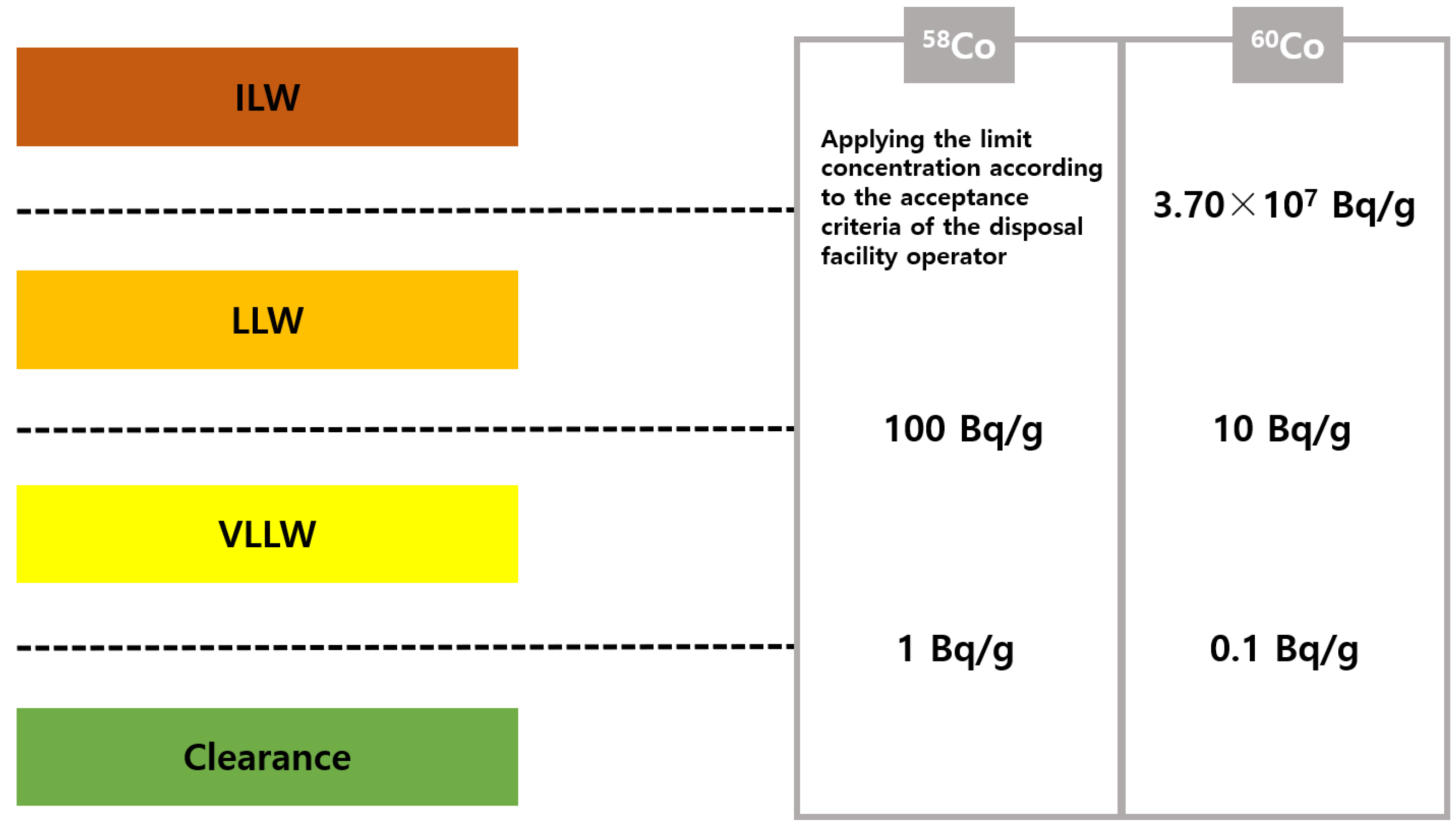
5.1. Regulation

In Korea, the classification and classification criteria for radioactive waste have been legislated by Notice No. 2017-65 of the Nuclear Safety and Security Commission (Regulations on the Classification and Clearance of Radioactive Waste). Depending on the concentration of each radionuclide, the waste is classified into intermediate-level (ILW), low-level (LLW), very low-level (VLLW) radioactive waste, and clearance waste, which includes the limit concentration of radioactivity for each radionuclide as determined by the committee [13].
By referencing the limit concentration for the clearance of each radionuclide (Appendix 1, Notice No. 2017-65) and the limit concentration of radioactivity for low-level radioactive waste (Appendix 2, Notice No. 2017-65), the specific activity of 58Co and 60Co for each level of radioactive waste can be summarized as shown in Figure 1.

5.2. Specific Activity of SG Tube

The allowable concentration for each waste level is limited in units of specific activity [Bq/g], which is the radioactivity per unit mass. Therefore, to know the level of the SG tubes, the total mass of the tubes is needed. However, the mass data for the tubes (Alloy-690) could not be found, so the SG data for Kori Unit 1 and the density of Alloy-690 shown in Table 13 were utilized to perform an analog calculation. This resulted in a prediction that the mass of the SG tubes would be approximately 45.3 tons.
Considering the mass of the SG tubes calculated, the average specific activities of 58Co and 60Co obtained when performing FSD are as shown in Table 14.

5.3. Radioactive Waste Level of SG Tube

The specific activity of 58Co can be ignored as it is below the limit concentration that can be classified as clearance waste, and only considering the specific activity of the 60Co nuclide, Table 15 illustrates the categorization of waste level for the SG tubes. Although it is possible to reduce the specific activity by about 1/1400 compared to when no FSD is performed if the largest DF value is obtained, it is expected that the level of the SG tubes will fall into low-level waste, whether FSD is performed or not. The low-level radioactive waste classification criterium for the 60Co nuclide is a specific activity of 10 Bq/g or more but less than 3.70 × 10⁷ Bq/g.

5.4. Storage Period Required for Clearance

The duration required for the SG tubes to be stored in a compressed state within a storage facility until they could be disposed of as clearance waste was examined. Table 16 shows the period required for the clearance of the SG tubes when compressed and stored, calculated by assuming one month as 30 days and considering the half-life of 60Co. Without performing FSD, the time required for clearance would be about 108 years. Even if FSD were performed and the highest efficiency was achieved in the decontamination of the SG tubes, it would be expected to take about 52 years until clearance.

6. Conclusions

This study predicted the radioactive inventory of SG tubes, which occupy about 80% of the total surface area when FSD is performed [2]. For this, the CRUDTRAN code, a primary coolant system source term prediction evaluation code, was used, and input parameters were prepared using Kori Unit 1 data by calculating the average operation and maintenance days from the cycles after SG replacement to the permanent shutdown. A comparison of the evaluation results from CRUDTRAN code with the actual measurement results obtained using a survey meter revealed that the results from the code are approximately 21% conservative.
Using these results, assuming that the FSD of Kori Unit 1 is performed on 1 December 2023, the radioactive inventory of the SG tubes was calculated to be 5.17 × 10¹² Bq. To verify the reduction in radioactivity from the SG tubes after FSD, five overseas NPPs with measured DF values from the SG tubes section during FSD were selected. The range of DF values is 12–1409, and the radioactivity of the SG tubes was estimated along with each DF value.
Finally, to estimate the waste level of the SG tubes, the limit concentrations of 58Co and 60Co for each level of radioactive waste, as regulated by Notice No. 2017-65 of the NSSC, were reviewed. In order to consider the limit concentration in the unit of specific activity [Bq/g], an analog calculation was made to predict the mass of the SG tubes in one steam generator using Kori Unit 1 SG data. The results of estimating the specific activity of the SG tubes and checking the radioactive waste level indicated that, regardless of whether FSD is performed, it is expected that the SG tubes would be classified as low-level radioactive waste. Even if a high efficiency of FSD is achieved, it will take more than 50 years to dispose of them for clearance if stored.
This study provided crucial insights into the challenges associated with achieving clearance of SG tubes through FSD. It has been confirmed that it is difficult to expect clearance of SG tubes with the FSD process. When including SG tubes, which account for approximately 80% of the total surface area for the FSD operation, one significant concern that emerged is the generation of substantial secondary waste, such as spent resin and radioactive wastewater. A higher number of cycles to achieve superior decontamination inevitably leads to an increased volume of such waste.
Given these challenges, it seems necessary to exclude the SG tubes, or even the entire SG, during FSD. Alternatively, segregating the SG tubes and employing a distinct decontamination method can also be considered. However, a thorough approach is essential to evaluate factors like potential worker exposure during SG tube dismantling, the financial implications arising from secondary waste management, etc. This study is expected to aid in determining the scope of full-system decontamination in the future.

Author Contributions

Conceptualization, S.-H.K. and C.-L.K.; methodology, S.-H.K.; software, S.-H.K.; validation, S.-H.K. and C.-L.K.; formal analysis, S.-H.K.; investigation, S.-H.K.; resources, S.-H.K. and C.-L.K.; data curation, S.-H.K.; writing—original draft preparation, S.-H.K.; writing—review and editing, S.-H.K. and C.-L.K.; project administration, C.-L.K.; funding acquisition, C.-L.K. All authors have read and agreed to the published version of the manuscript.

Funding

This research was funded by Korea Institute of Energy Technology Evaluation and Planning and the Ministry of Trade, Industry & Energy (MOTIE), KETEP No. 20204010600130.

Conflicts of Interest

The authors declare no conflict of interest.

References

  1. Kim, H.S.; Kim, J.J.; Kim, C.R. Evaluation of System Design Modifications for Full System Decontamination of Kori Unit 1. Nucl. Eng. Technol. 2022, 54, 3949–3956. [Google Scholar] [CrossRef]
  2. Mitsubishi Heavy Industries, Ltd.; Nuclear Plant Service Engineering Co., Ltd. The First FSD due to the Measures Associated with PWR Including SG Contains Nickel Base Alloy Materials (Inconel 690). E-J. Adv. Maint. 2019, 10, NT92. Available online: http://www.jsm.or.jp/ejam/Vol.10No.4/NT/NT92/92.html (accessed on 15 June 2023).
  3. Betova, I.; Bojinov, M.; Saario, T. Start-Up and Shut-Down Water Chemistries in Pressurized Water Reactors; VTT-R-00699-12; VTT: Espoo, Finland, 2012; pp. 5–10. [Google Scholar]
  4. Song, J.S.; Kim, H.M.; Lee, S.H. A Study on Radioactive Source-term Assessment Method for Decommissioning PWR Primary System. J. Nucl. Fuel Cycle Waste Technol. 2014, 12, 153–164. [Google Scholar] [CrossRef] [Green Version]
  5. Park, G.Y.; Kim, C.L. Chemical Decontamination Design for NPP Decommissioning and Considerations on its Methodology. J. Nucl. Fuel Cycle Waste Technol. 2015, 13, 187–199. [Google Scholar] [CrossRef]
  6. Lee, C.B. Evaluation of CRUDTRAN Code to Predict Transport of Corrosion Products and Radioactivity in the PWR Primary Coolant System. In Proceedings of the CHIMIE 2002 International Conference on Water Chemistry in Nuclear Reactors System, Avignon, France, 22–26 April 2002. [Google Scholar]
  7. Rafique, M.; Mirza, N.; Mirza, S.M.; Iqbal, M.J. Review of Computer Codes for Modeling Corrosion Product Transport and Activity Build-up in Light Water Reactors. Nukleonika 2010, 55, 263–269. [Google Scholar]
  8. Park, J.H.; Cho, S.Y.; Kim, J.J.; Lee, C.B. A Study on the Assessment of the Radioactivity Inventory Deposited in the Reactor Coolant System during the Decommissioning of Kori Unit 1. J. Radiat. Ind. 2022, 16, 81–92. [Google Scholar]
  9. An, Y.S.; Lee, J.H.; Yang, H.Y.; Kim, K.D.; Ha, J.H. Characteristics on Contamination and Generation of Radioactive Metal Wastes for Decontamination Process Application. In Proceedings of the Korean Nuclear Society Autumn Meeting, Taejon, Republic of Korea, 26–27 October 2000. [Google Scholar]
  10. AREVA. Recent Experience with Full System Decommissioning (FSD) prior to Decommissioning in PWRs and BWRs with CORD® Family and AMDA® Technology. In Proceedings of the 8th EPRI International Decommissioning and Radioactive Waste Management Workshop, Hamburg, Germany, 6–8 October 2009; pp. 200–243. [Google Scholar]
  11. Enresa. Impact of the Full System Chemical Decontamination on the Jose Cabrera NPP Decommissioning; Gobierno de Espana: Brussels, Belgium, 2016. Available online: http://www.isoe-network.net/publications/pub-proceedings/symposia-thematic/rp-at-decommissioning-stage/decontamination-1/3484-campos2016-ppt-1/file.html (accessed on 15 June 2023).
  12. Dubourg, M. Hard Chemical Decontamination of Steam Generator Tube Bundles. J. Nucl. Eng. Des. 1995, 159, 123–129. [Google Scholar] [CrossRef]
  13. NSSC. Regulations on the Classification and Clearance of Radioactive Waste; Korean Nuclear Safety and Security Committee (NSSC) Notice No. 2017-65; NSSC: Daejeon, Republic of Korea, 2017. [Google Scholar]
  14. Korea Electric Power Corporation. Kori Unit 1 Steam Generator Replacing Experience Report, 3rd ed.; Korea Electric Power Corporation: Naju-si, Republic of Korea, 1999; p. 33. [Google Scholar]
Figure 1. Specific activity of 58Co and 60Co for each level of radioactive waste.
Energies 16 05787 g001
Table 1. Characteristics of major radioactive corrosion products [4].
NuclideReaction FormulaHalf-LifeGamma Energy
[MeV]
Major Creation
51Cr50Cr(n,r) 51Cr27.7 days0.30S/S, Inconel
54Mn54Fe(n,r) 54Mn312.2 days0.83S/S
55Fe54Fe(n,r) 55Fe2.7 years-S/S
59Fe58Fe(n,r) 59Fe44.5 days1.18S/S
58Co58Ni(n,p) 58Co70.9 days0.81S/S, Inconel
60Co59Co(n,r) 60Co5.3 years1.25Inconel
95Zr94Zr(n,r) 95Zr64.0 days0.74Zry
Table 2. Contaminated layers status and DF [5].
LayerDepthMaterialDF
Outer layer1–5 μmFe2O3, iron-rich1–5
Intermediate layer
(CRUD)
2–10 μmFeCr2O4, Cr2O3, chromium-rich5–50
Base alloy5–30 μmFe, Cr, Ni50–10,000
Table 3. Input parameters and data for CRUDTRAN code.
(1) Calculation parameterInput dataUnit
DAYS—duration of operation32, 64, 64, 64, 64, 32, 32, 55 or 54, ∙∙∙day
IN—time step size of numerical calculation0.1day
NTMA—number of time steps per printing output10
NTS—number of meshes in the numerical integration of solubilityby temperature (normally 1 < nts < 50) 10
BETAC—crud transport factor in CRUDTRAN0.02
BETAA—activity transport factor in CRUDTRAN0.002
(2) Plant operating conditionInput dataUnit
BORON—concentration of boron 955, 755, 595, 415, 235, 145, 55, 2000ppm
ALIT—concentration of LiOH 2.2, 2.2, 2.2, 2.2, 2.2, 1.3, 0.8, 0.63ppm
CH2—hydrogen content 34cc/kg-H2O
FLOW—coolant flow rate 7.23 × 10⁸kg-H2O/day
ONOFF—coolant flow on or off (1 or 0)1
P1—% power for calculation of neutron activation100%
TIN—core inlet temperature282°C
TOUT—core outlet temperature at full power320°C
DTBL1—temperature differences across the boundary layer in the core at full power18 1.°C
DTBL3—temperature difference across boundary layer in S/G at full power−5.4 1.°C
FPUR—bypass flow rate of purification system 6.5 × 10⁵kg-H2O/day
DEN—density of the average coolant 963.05kg/m3
VIS—viscosity of average coolant3.0919 × 10−7nsec/m2
(3) Initial conditionsInput dataUnit
IH—initial crud inventory in the core1.0 × 10−20kg-Fe
IC—initial crud inventory in S/G 1kg-Fe
AH1—initial cobalt-60 activity in core 0Ci
AH2—initial cobalt-58 activity in core 0Ci
AC1—initial cobalt-60 activity in S/G 0Ci
AC2—initial cobalt-58 activity in S/G 0Ci
AD1—initial cobalt-60 activity in the purification system0Ci
AD2—initial cobalt-58 activity in the purification system 0Ci
(4) OptionInput dataUnit
IREF—refueling of fuel assemblies, on or off (1 or 0)1
IPAR—particulate precipitation in coolant, on or off (1 or 0)0
NRF—no. of refueling times16
RF(i)—refueling time407, 814 (= 407 + 407), 1221 (= 814 + 407), 1628 (= 1221 + 407), ∙∙∙day
(5) Output print optionInput dataUnit
INPRIN—print of input data and detailed output, on or off (1 or 0)1
(6) Plant geometryInput dataUnit
DE1—hydraulic diameter of the core fuel channel 1.48 × 10⁻²m
DE3—hydraulic diameter of S/G tube1.69 × 10−2m
AR1—surface area of core 2,523m2
AR3—surface area of S/G 10,237m2
AF1—coolant flow area in the core 2.715m2
AF3—coolant flow area in S/G 2.04m2
(7) Diffusion coefficientsInput dataUnit
DSOL—diffusion coefficient of soluble1.08 × 10−8m2/sec
DPAR—diffusion coefficient of particulate 6.9 × 10⁻¹⁰m2/sec
(8) Radioactivity parametersInput dataUnit
ALPH1—cobalt-60 production rate in core2.8 × 10−3 1.60Co Ci/(kg-Fe∙day∙%power)
ALPH2—cobalt-58 production rate in core 8.4 × 10⁻² 1.58Co Ci/(kg-Fe∙day∙%power)
LAMD1—decay constant of cobalt-60 3.6 × 10⁻⁴/day
LAMD2—decay constant of cobalt-58 9.78 × 10⁻³/day
(9) Recoil releaseInput dataUnit
RR58—fractional recoil release of cobalt-58 produced by (n,p)2.5 × 10⁻¹ 1.
RR60—fractional recoil release of cobalt-60 produced by (n,p)0 1.
(10) Crystal growth and dissolutionInput dataUnit
HCRYSC—crystal growth coefficient of corrosion product in core 6.0 × 10⁻⁵m/sec
HCRYSA—crystal growth coefficient of activity in S/G 6.0 × 10⁻⁶m/sec
HDISSC—dissolution coefficient of corrosion product in S/G 6.0 × 10⁻⁵m/sec
HDISSA—dissolution coefficient of activity in core 6.0 × 10⁻⁶m/sec
(11) Other parametersInput dataUnit
CR—corrosion rate of S/G tube4.9 × 10−2kg/day
1 Input data from CRUAS Unit 1 in France.
Table 4. Operation and maintenance history of Kori Unit 1 [8].
Core Cycle No.Operation StartMaintenance StartMaintenance StopOperation Period [Days]Maintenance Period [Days]
186 September 19985 September 199929 October 199936454
1929 October 199915 October 200018 November 200035234
2018 November 200016 November 200112 December 200136326
2112 December 200129 January 200328 February 200341330
2228 February 200326 February 200421 March 200436324
2321 March 20048 March 200510 May 200535263
2410 May 20055 May 200610 June 200636036
2510 June 20069 June 20079 January 2008364214
269 January 200820 November 20089 December 200831619
279 December 200816 December 20098 January 201037223
288 January 201013 January 20111 February 201137019
291 February 20111 February 20121 March 201236529
301 March 201212 April 20135 October 2013407176
315 October 201325 February 201417 April 201414351
3217 April 201425 April 20157 June 201537343
337 June 201523 June 201630 July 201638237
3430 July 201618 June 2017 323
Table 5. Variables in each operation phase per cycle [8].
Operation Duration [Days]Cumulative Operation [Days]Boron Concentration [ppm]LiOH Concentration [ppm]Flow Rate
[kg-H2O/Day]
T_in
[°C]
T_out
[°C]
32329552.20.723 × 109282320
64967552.20.723 × 109282320
641605952.20.723 × 109282320
642244152.20.723 × 109282320
642882352.20.723 × 109282320
323201451.30.723 × 109282320
32352550.80.723 × 109282320
55 or 54407 or 40620000.631.15 × 109286323.2
Table 6. CRUD concentration and surface activities of Kori Unit 1 from CRUDTRAN code.
S/G Fe-CRUD [mg-Fe/cm2]Core Fe-CRUD
[mg-Fe/cm2]
60Co S/G [uCi/cm2]58Co S/G [uCi/cm2]60Co Core [uCi/cm2]58Co Core [uCi/cm2]60Co Coolant [uCi/cm3]58Co Coolant [uCi/cm3]
2.69 × 1008.87 × 10−26.26 × 1004.26 × 1004.83 × 1002.48 × 1017.26 × 10−53.23 × 10⁻⁴
Table 7. SG tube radioactivity on 11 August 2017.
NuclideSG Tube Radioactivity [Bq]
(On 11 August 2017)
60Co1.19 × 1013
58Co8.07 × 1012
Total1.99 × 1013
Table 8. Measured radiation dose rate and radioactivity of SG tube [8].
ComponentRadiation Dose Rate [mSv/h]Radioactivity [Bq]
SG tube A0.145.88 × 1012
SG tube B0.145.88 × 1012
Table 9. SG tube radioactivity on 7 July 2021.
NuclideSG Tube Radioactivity [Bq]
(On 7 July 2021)
60Co7.09 × 1012
58Co7.06 × 106
Total7.09 × 1012
Table 10. SG tube radioactivity on specific date (1 December 2023).
NuclideSG Tube Radioactivity [Bq]
(1 December 2023)
60Co5.17 × 1012
58Co1.33 × 103
Total5.17 × 1012
Table 11. Features of overseas FSD cases [2,10,11].
NPPNet Performance [MW]Operation YearFSD MethodNo. of CyclesDF
(SG Tube)
Jose Cabrera1601968–2006DfDPhase 1: 3 Nitrox cycles + 2 DfD cycles
Phase 2: 1 DfD cycle
Phase 3: 4 DfD cycles (only CVC and RHR systems)
12
Mihama-13401970–2010HP/CORD UV389
Mihama-25001972–2011HP/CORD UV4174
Stade6801972–2003HP/CORD UV4400 (Maximum)
Obrigheim3571972–2003HP/CORD UV41409
Table 12. Estimated radioactivity of SG tube after FSD.
NuclideNo FSDDF
12891744001409
60Co5.17 × 10124.31 × 10115.81 × 10102.97 × 10101.29 × 10103.67 × 109
58Co1.33 × 1031.11 × 1021.49 × 1017.63 × 1003.32 × 1009.42 × 10−1
Total5.17 × 10124.31 × 10115.81 × 10102.97 × 10101.29 × 10103.67 × 109
[Unit: Bq].
Table 13. Specifications of SG tubes in Kori Unit 1 [14].
ParameterValueUnit
Tube height (starting from the top of the tube sheet)368in
Minimum radius of U-bend3.25in
Maximum radius of U-bend58.25in
Tube inner diameter0.664in
Tube outer diameter0.75in
No. of tubes4934
Density of Alloy-6908.19 × 106g/m3
Mass of Alloy-6904.53 × 107g
Table 14. Average specific activity of SG tube after FSD.
NuclideNo FSDDF
12891744001409
60Co1.14 × 1059.52 × 1031.28 × 1036.57 × 1022.86 × 1028.11 × 101
58Co2.93 × 10−52.44 × 10−63.29 × 10−71.68 × 10−77.33 × 10−82.08 × 10⁻⁸
[Unit: Bq/g].
Table 15. Estimated radioactive waste level of SG tube.
No FSDDF
12891744001409
LLWLLWLLWLLWLLWLLW
Table 16. Required period for clearance of SG tube.
No FSDDF
12891744001409
107.688.473.067.861.451.7
[Unit: years].
Disclaimer/Publisher’s Note: The statements, opinions and data contained in all publications are solely those of the individual author(s) and contributor(s) and not of MDPI and/or the editor(s). MDPI and/or the editor(s) disclaim responsibility for any injury to people or property resulting from any ideas, methods, instructions or products referred to in the content.

