Abstract
Concentrating photovoltaic thermal (CPVT) solar collectors can be regarded as a promising technology, as they are capable of providing renewable electricity and industrial heat simultaneously. The development of a novel CPVT receiver for a linear Fresnel concentrator requires detailed knowledge about the optical performance of the utilised mirror field. Therefore, this paper presents a generic optical model for such concentrating solar systems. The model was developed in MATLAB™ and calculates the sun’s position depending on the location, date and time. The subsequent geometrical computation of each mirror stripe angle is the basis for the detailed consideration of internal shading mechanisms that are typical for Fresnel mirror concentrators. Furthermore, the cosine losses are determined separately for each mirror. The outcomes of the developed model comprise the optical performance parameters of the considered Fresnel mirror field, such as the geometric efficiency, resulting irradiance in the receiver input plane, expected width of the focus image, concentration factor and total radiant flux impinging the receiver. Due to the chosen design of the model, its application is not limited to a particular kind of Fresnel concentrator. By contrast, all geometric parameters, such as the number of mirrors, the dimensions of the mirrors and the receiver, among others, can be freely adjusted.
1. Introduction
The necessity of using solar energy to address one of the key issues that humankind currently faces, i.e., the transition of the global energy supply system towards renewable sources, is indisputable. The two main technologies that are used to convert solar radiation into useful energy are photovoltaic (PV) and solar thermal (ST) systems. Both systems are currently available on a high level of maturity, and both are making a noticeable contribution to provide emission-free power and heat [1]. Furthermore, the combination of PV and ST in one component (PVT) has been in the focus of research for more than 40 years. Although it is still in an early stage of market penetration, it has major growth potential [2]. In recent years, PVT systems were able to achieve significant global growth rates of up to 13% in terms of installed capacity, and supplied a total thermal power of 751 MWth and a total electrical power of 254 MWel by the end of 2021. However, 99.7% of these systems utilise non-concentrating PVT collectors, providing emission-free heat at temperature levels for domestic hot water generation and space heating support [3]. If applications in the industrial sector with temperature requirements above 100 °C are to be supplied with solar heat and solar electricity, concentrating PVT (CPVT) has to be considered. The present market share of CPVT is marginal, because such hybrid collectors face the fundamental challenge that both parts of the receiver, the thermal part and the electrical one, require opposing temperature levels to provide both forms of energy effectively and efficiently. While the thermal receiver generates temperatures of 150 °C and more, the temperature of the PV cells in the electrical part of the receiver must not exceed the limit of 85 °C, which is normally set by the specification of the encapsulation plastic [4,5].
One possible way to address this challenge is by using the “Spectral Splitting” approach. The central idea of this concept is to split the concentrated incidental irradiance into several spectral domains and to supply each part of the receiver with the most suitable bandwidth. The electrical receiver part is only impinged with a wavelength range where the spectral response of the PV cells reaches maximum values, and hence, where the energy conversion in the cells is the most efficient. All other spectral bands are less suitable for the generation of electricity in the PV cells, either because incidental photons carry too much energy, which causes thermalisation losses within the semiconductor, or because the photon energy is too low to overcome the bandgap. These non-suitable spectral ranges would cause additional heating of the PV cells, and therefore, they are absorbed by an optical filter and directly converted into heat within the thermal receiver part, where the generated heat becomes accessible. Furthermore, the receiver parts are thermally decoupled from each other in order to reduce undesired heat transfer.
The application of spectral splitting in CPVT receivers has been investigated for some decades with a large number of different constructions and various solutions for realising the optical filtering [6,7,8,9,10]. Recent research work in this field has revealed promising results in terms of raising the energy conversion efficiency of such solar hybrid systems. Han et al. [11] modelled a receiver construction with tubular optical filters and reported a potential efficiency increase from 12.73% in the PV-only operation mode to 46.77% in the combined electrical–thermal operation of the concentrating system. A different constructional approach was chosen by Huang et al. [12], who proposed the use of an evacuated layer between the thermal and the electrical receiver parts for minimising heat losses. Their modelling efforts resulted in a CPVT system with a maximum outlet temperature of 412 °C. Besides the technical performance modelling, Wang et al. [13] also investigated the economic parameters for a possible implementation of concentrating hybrid collectors for supporting the energy demand of a dairy farm. The experimental results of the performance measurements using spectral splitting CPVT collectors were reported by Stanley et al. [14], who achieved a thermal efficiency of 31% at an outlet temperature of 120 °C, and an electrical efficiency of 3.8%.
The authors of this paper are presently working on the development and experimental implementation of a compact CPVT receiver for a linear Fresnel concentrator, including spectral splitting via absorptive filtering. A detailed description of the completed receiver design process can be found in [15]. One of the novelties of their construction is the utilisation of bendable CIGS PV modules representing the electrical receiver part [16]. Secondly, triethylene glycol was successfully tested for its implementation in the CPVT receiver, both as a heat transfer fluid and as the liquid part of the required optical filter [17]. During the receiver design process and for the subsequent stage of experimental realisation, detailed knowledge about the optical performance of the considered Fresnel mirror field was required. On the one hand, the expected width and position of the focus image in the receiver input plane influenced the design of the CPVT receiver, and on the other hand, the magnitude of the resulting concentrated irradiance at different sun positions is the main parameter for simulating electrical and thermal power, energy yields and efficiencies. Therefore, the investigation of the given Fresnel mirror field via optical modelling was essential.
Optical models for concentrating solar systems have been developed in the past via various research activities. Boito and Grena [18] worked on maximising the optical efficiency of a Fresnel collector by optimising certain geometrical parameters, e.g., the mirror positions. The provided MATLAB model uses fixed values for the number of mirrors, the receiver height above the mirrors and the receiver width. Widyolar et al. [19] showed the utilisation of the ray-tracing software LightTools for optimising the design of a spectrum splitting hybrid receiver to be mounted on a parabolic trough concentrator. Wang et al. [13] also investigated a parabolic trough collector and modelled the optical efficiency of the system by using MATLAB and Microsoft Excel. The shadowing effects, tracking and geometry errors were considered via empirical parameters and correction terms. The optical model created by Han et al. [11] for a Fresnel mirror field with a CPVT receiver was developed via ray-tracing methods using LightTools. Although these outcomes appear to be quite useful in terms of identifying the flux intensity on the receiver input plane, the incident angle was assumed to be constantly zero. Therefore, only vertical rays are considered, and hence, the shading losses within the Fresnel mirror field are mostly neglected. By contrast, Boito and Grena [20] developed an optical model for Fresnel systems that also calculates the impact of the shadowing mechanisms that are typical for such concentrators. However, the target application in this case was not CPVT, but concentrating PV, and the simulation outputs focussed on the daily and annual electrical energy production. Montenon et al. [21] used the ray-tracing software Tonatiuh++ to compare two receiver designs for a thermal linear Fresnel collector. This work confirms that ray tracing can be very useful for evaluating concentrating solar systems, although the research focus was on the optical modelling of the receiver and not on the Fresnel mirror field itself. Besides the mentioned modelling approaches, Fernández-Reche et al. [22] explored a method for measuring the concentrated solar radiation flux on a novel type of Fresnel mirror field. The developed measurement device consists of a CMOS camera and a water-cooled Gardon radiometer and can be used to confirm the results of ray-tracing simulations. According to Fernández-Reche et al., other systems for the direct measurement of concentrated solar flux are scarcely available [22]. Another novel type of Fresnel collector was investigated by Wang et al. [23], who calculated the optical efficiency using the ray-tracing software Soltrace. The cross section of this multi-mirror concentrator is similar to a parabolic trough, and therefore, the internal shading mechanisms are immaterial within this investigation.
Although many valuable results of modelling the optical behaviour of concentrating solar systems can be found in the literature, a distinct optical model had to be developed for the use described herein, due to several requirements that could not be satisfied by the available solutions. On the one hand, the required optical model should be created in MATLAB™ to be able to merge it with the electrical and thermal models of the developed CPVT receiver in a subsequent step. On the other hand, maximum flexibility in terms of the concentrator geometry should be provided by the optical model, because the mounting height and the width of the receiver were not determined at that stage of development. Even the number of mirrors should be set as a variable, which would allow for the application of the model not only in the given Fresnel mirror field, but in any other field as well. Some of the mentioned publications do not consider internal shading mechanisms, although other research has proven the substantial impact of the typical shadowing effects in Fresnel concentrators on the optical performance [13,20,24]. Therefore, the development of a unique MATLAB™ model should also include internal shading losses. One limitation was that the detailed optical modelling of the inner structure of the CPVT receiver was not required at this stage; however, this can be seen as a potential extension in the future.
The present paper describes the development of a generic optical model for linear Fresnel concentrators with a high flexibility in terms of geometrical arrangement. The number of mirrors and all of the constructional parameters of the mirror field are set as input variables, providing us with the possibility to optimise the optical performance of the concentrator. Four types of internal shading effects are considered by the calculation. Depending on the location, date, time and the incident direct normal irradiance (DNI) taken from measurements or climate data sets, the MATLAB™ model yields relevant data like the concentration factor, optical efficiency, local and mean irradiance on the receiver input plane, among others.
2. Materials and Methods
The Fresnel mirror field displayed in Figure 1 is the basis for the primary objective of developing a novel CPVT receiver using spectral splitting. It was manufactured by the company FRESNEX from Austria, the technology of which was acquired from the company ECOTHERM, also located in Austria. The mirror field has gross dimensions of 5.8 m × 2.3 m. It contains 28 plane mirror stripes with a width of 70 mm and a length of 5.72 m, mechanically connected and moved via a DC servo motor and a central control bar. Further mechanical details of the mirror field are described in [25].
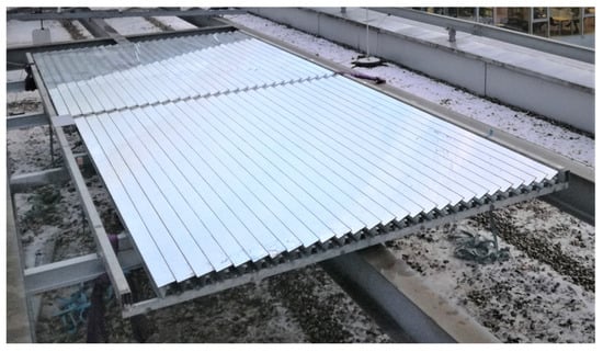
Figure 1.
Fresnel mirror field at the University of Applied Sciences Upper Austria in Wels, Austria.
The development of an optical model for this Fresnel concentrator was essential for obtaining the following information, which is required for developing and implementing a proper CPVT receiver:
- Appropriate receiver mounting height above mirror field;
- Resulting width of focus image in receiver input plane for defining minimum receiver width;
- Resulting irradiance and radiant flux on receiver input plane, depending on location, date and time, for measured or simulated DNI.
Furthermore, the model should be designed in a general way to be applicable for different types and sizes of Fresnel mirror fields, not only for the specific one under investigation. Therefore, the following approach was chosen to develop the model in MATLAB™:
- Calculation of the sun’s position, depending on location, date and time;
- Geometrical calculation of mirror angles depending on transversal solar zenith angle ;
- Modelling of shading mechanisms, depending on ;
- Consideration of cosine losses;
- Calculation of resulting optical performance parameters.
The flowchart in Figure 2 illustrates the applied sequence of the single calculation steps within the developed optical model.
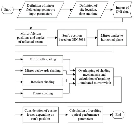
Figure 2.
Flowchart of the simulation steps of the developed optical model [26].
Due to its large extent, the entire MATLAB code is not included in this paper, although it can be provided by the corresponding authors if required. However, the following sub-sections describe the most relevant calculation steps of the model.
2.1. Calculation of Sun Position
The approach for calculating the sun´s position depending on location, date and time, implemented in the developed mirror field model, is based on the standard DIN 5034 [26]. It is also partly described in [5,27,28], but was slightly modified in terms of variable names for this use case.
This algorithm reckons the exact solar declination depending on the earth´s position on solar orbit on the considered day of the year as follows:
The time deviation is calculated using the following equation:
Based on the local time , the time zone and the longitude of the considered solar collector site, the average local time is obtained as follows:
The real local time is calculated using Equation (5),
and transformed into the hour angle as follows:
Combined with the latitude of the collector site, the sun’s elevation angle and the azimuth angle are computed in the following way:
The azimuth angle is zero when reaches its maximum. Therefore, is negative according to Equation (8) for , and positive for . The solar zenith angle is the complement angle to the sun´s elevation angle as follows [29]:
Two characteristic geometrical planes are defined for the Fresnel mirror concentrators. The longitudinal plane is spanned between the receiver axis and the vertical axis, whereas the transversal plane is aligned perpendicularly to the longitudinal plane [24]. The solar zenith angle projected into the transversal plane results in and is reckoned as follows [24]:
Hence, the solar elevation angle projected into the transversal plane is the complement angle to as follows:
Both angles projected into the transversal plane, and , are the basis for calculating the position of the separate mirror stripes, as described in the following sub-section.
2.2. Geometric Calculation of Mirror Angles
The mirror angles to the horizontal plane were obtained by applying the method of backward ray tracing [24], reduced to only one beam per mirror. Figure 3 shows the cross section of an exemplary Fresnel collector with 10 mirrors (in blue) at a transversal solar zenith angle of 45°. The receiver is simplified to a square cross section (in black). In backward ray tracing, one traced ray per mirror starts from the focal point of the receiver (dashed lines in red) and hits the centre of the corresponding mirror, where it is reflected (solid lines in orange) according to the law of reflection [30]. Figure 3 also provides the enlargement of two adjacent mirrors for describing the chosen angle definitions and geometric parameters.
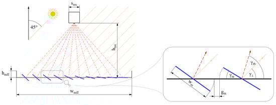
Figure 3.
Cross section of an exemplary Fresnel collector with 10 mirrors at , including enlargement of two adjacent mirrors.
The following input parameters are required for calculating the mirror angles:
- Width of mirror field frame ;
- Number of mirror stripes ;
- Width of each mirror stripe ;
- Horizontal gap between two adjacent mirrors ;
- Mounting height of the receiver above mirror plane .
With this information, the mirror fulcrum positions relative to the centre of the mirror field are determined. Subsequently, the angle of the reflected beams (dashed red lines in Figure 3) to the horizontal plane is calculated as follows:
where is the index of the particular mirror under calculation, running from 1 to . The angle between the normal of each mirror and the horizontal plane is the half angle between the incident beam in the transversal plane and the reflected beam
The mirror angles to the horizontal plane are calculated using the following equation:
As mentioned in the introduction to this section, the mounting height of the receiver above the mirror plane should be a result of the optical model, although it is required as an input variable for calculating the mirror angles, according to Equation (12). Therefore, it was necessary to solve this implicit problem by varying iteratively between 600 mm and 2400 mm, which appeared to be a meaningful range for the considered Fresnel mirror field.
2.3. Modelling of Shading Mechanisms
In contrast to parabolic trough concentrators, the optical performance of Fresnel mirror fields is significantly influenced by internal shading mechanisms, namely, the mirror self-shading, the mirror backwards shading, the receiver shading and the frame shading [13,20,24]. Figure 4 illustrates these shading effects for a generic Fresnel mirror field with 10 mirrors.
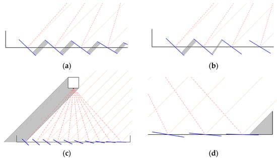
Figure 4.
Shading mechanisms in an exemplary Fresnel mirror field: (a) mirror self-shading (scaled view); (b) mirror backwards shading (scaled view); (c) receiver shading; (d) frame shading (scaled view).
Mirror self-shading occurs when the incident beams cannot illuminate the full width of a mirror because it is partly covered by the adjacent mirror (see Figure 4a). Self-shading can be observed at large transversal solar zenith angles and, therefore, correspondingly large mirror angles . The developed MATLAB™ model considers this effect by calculating the shading line starting from the upper edge of a mirror and running in parallel to the incident beams down to the surface of the shadowed mirror.
Mirror backwards shading describes the phenomenon of when a part of the reflected beams hits the backside of an adjacent mirror and does not reach the receiver (see Figure 4b). The calculation of this shading mechanism within the optical model is performed in a similar way like the self-shading, although the angle of the shading line is not the angle of the incident beam, but the angle of the reflected beam to the horizontal plane.
Receiver shading is another relevant effect that influences the illumination of the mirror field and is illustrated by Figure 4c. Depending on the dimensions and geometries, the shade of the receiver starts to enter the mirror field with decreasing transversal solar zenith angles . The MATLAB™ model calculates both shading boundary lines of the receiver and detects the intersections with the affected mirrors.
Frame shading is caused by the mechanical structure of the Fresnel mirror field, as visualised in Figure 4d. The model calculates the resulting shading line, starting at the upper edge of the collector frame, defined by the input parameter , and going downwards, with the angle of the incident beams. Depending on , one or more mirrors can be shaded partly or totally by the frame, leading to a reduction in the illuminated mirror surface and, therefore, to a decreased optical performance of the mirror field.
The developed optical model computes separately for each mirror, which kind of shading effect reduces the illuminated surface by which amount. The overlapping of two or more shading mechanisms may occur, e.g., when the receiver shadow superimposes self-shading of two mirrors, which is also detected by the model. The output information of this calculation part is the remaining illuminated width for each mirror stripe.
2.4. Consideration of Cosine Losses
As concentrating solar systems only convert into useful energy, the developed optical model requires this essential input parameter for calculating the resulting irradiance and radiant flux in the receiver input plane. The information of can either be taken from measurements or from climate data sets but needs to be corrected by the angle of incidence , as only the portion of the incident radiation that is perpendicular to the horizontal input plane is of interest for calculating the performance parameters of the CPVT receiver, such as the thermal and electrical efficiency.
The calculation of is based on the angle definition illustrated in Figure 5, assuming a north–south alignment of the mirrors. The incident sun beam impinges on the mirror field at an azimuth angle and a solar zenith angle . The reflected beam represented by the vector leaves the mirror at a transversal angle and a longitudinal angle , and enters the receiver input plane at an angle related to the perpendicular vector . is the longitudinal fraction of and is calculated in the following way [24]:
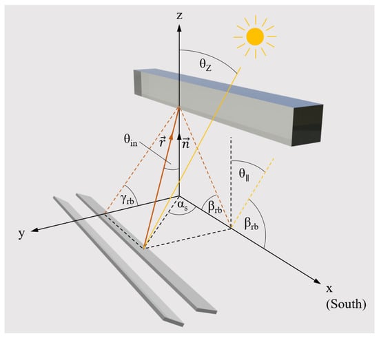
Figure 5.
Angle definition on the Fresnel mirror field.
The longitudinal angle of the reflected beam results in the following:
Vector can be described by its magnitude and its unit vector , given by the corresponding x, y and z components, as follows:
The unit vector is oriented in the z-direction and can be divided into its components as follows:
The incident angle is obtained from the scalar product of and as follows [31]:
The perpendicular fraction of , corresponding to the relevant magnitude of entering the receiver, can be directly calculated via an orthogonal projection onto the vector [31], as expressed by Equation (20). Moreover, reflexion losses of the mirrors are considered by a factor as follows:
As the angle of reflected beam is different for each mirror stripe, the optical model calculates separately for each mirror. Therefore, the index is used again to distinguish the different values of incident irradiance, .
2.5. Optical Performance Parameters
As mentioned in the introduction of this section, the development of an optical model for Fresnel concentrators had the aim of optimising the receiver mounting height and the dimensions of the receiver´s cross section, as well as predicting the resulting irradiance in the receiver input plane. Therefore, the following optical performance parameters are calculated using the model.
The geometric efficiency yields the ratio between the illuminated (active) mirror surface and the total mirror surface, based on the modelling of the shading mechanisms described above. As the internal shading is only a matter of transversal irradiance, is not affected by the longitudinal dimension of the mirror stripes, and therefore, the calculation of is reduced to the ratio between illuminated width and total mirror width instead of mirror surface. depends on the elevation angle in transversal plane and the resulting shading effects and is calculated separately for each mirror. Subsequently, is computed as follows:
is an instantaneous value, as changes constantly. By contrast, calculating the arithmetic average of over the day, corresponding to the full range of from 5° to 90°, yields a more general performance parameter for the comparison of different concentrator geometries. Therefore, the mean geometric efficiency is introduced as follows:
The chosen resolution of is 1°. The starting value of is set to 5°, as lower values would not be meaningful due to the mechanical limitation of the mirror tracking.
Another important performance parameter is the resulting local irradiance in the receiver input plane . As an assumption, the distribution of the local irradiance in the longitudinal direction of the receiver is considered as even, and therefore, the calculation of is restricted to the transversal dimension (x-direction) of the receiver cross section. For the calculation of , the full width of the receiver is sampled by an iterative loop within the model, applying a resolution of 0.1 mm. Each step of this loop checks if the corresponding x-position on the receiver is illuminated or if it is affected by any shading. In case of illumination, the separate values calculated for all mirrors are overlapped to a resulting irradiance value , given in kW/m2. Moreover, the total width of the focus image is obtained by summing up the illuminated x-positions.
As can vary significantly within the illuminated width in the receiver input plane, it appeared to be meaningful to calculate an average value of the resulting irradiance, . This mean value is related to the focus image width for the considered moment, and therefore, it is also an instantaneous value, as the sun´s position is steadily changing. The calculation of is performed in the following way:
The factor in Equation (23) expresses the number of sample points per mm for detecting the illuminated receiver width, which is 10 mm−1 in the present case. is given in mm.
The real concentration factor is another value that steadily changes with the sun´s position and is calculated using Equation (24) as follows:
can be taken from measurements or from climate data sets for the considered collector site and needs to be given in kW/m2.
The total radiant flux impinging the receiver input plane in the perpendicular direction is computed as follows:
The parameter describes the length of the receiver, given in m. For the current research project, concerning the development of a CPVT collector, was chosen with a value of 1.5 m, as this will be a reasonable size for the subsequent prototyping phase.
2.6. Simplifications in the Model
The developed MATLAB™ model contains the following simplifications:
- The reflectivity of the mirror stripes is assumed to be constantly 90%. It does not consider any dependency on the angle of incidence and does not distinguish between different wavelengths.
- Possible tracking errors are neglected.
- The applied ray tracing simplifies the direction of solar radiation to parallel beams only.
- The receiver input plane is supposed to be planar for the current version of the optical model. However, as the currently available design concepts of the authors include a circular cross section of the CPVT receiver [15,16], this simplification needs to be revised in an ensuing version, in case the proposed receiver designs are implemented into a prototype.
- Row end losses are not considered by the model, as it is currently designed to simulate a single Fresnel mirror concentrator instead of an entire plant. The related CPVT receiver with an assumed length of 1.5 m is much shorter than the mirror field, which has a length of 5.8 m, and therefore, the mounting position in the longitudinal direction can be chosen in a way that no row end losses occur.
2.7. Overview of Model Input Parameters
Table 1 provides an overview of the chosen values for the required input parameters of the optical model. For some parts, the simulation was performed in an iterative way, and therefore, ranges for some parameters were defined. Moreover, Table 1 contains the real values of some design parameters of the present Fresnel concentrator as displayed in Figure 1.

Table 1.
Overview of input parameters used for optical model of Fresnel concentrator.
3. Results
This section presents the most relevant outcomes of the developed optical model for Fresnel mirror concentrators. The optical performance parameters defined in Section 2.5 are generally calculated for varying geometrical arrangements of the concentrator, but are also quantified specifically for the Fresnel mirror field that is presently under study at the University of Applied Sciences Upper Austria in Wels, Austria. Finally, the experimental validation of parts of the modelling results is described.
3.1. Geometric Efficiency of Fresnel Mirror Concentrator
As mentioned in Section 2, the internal shading mechanisms within the Fresnel mirror field are highly dependent on the sun´s elevation angle in the transversal plane. Figure 6 illustrates this coherence, where the geometric efficiency is calculated for transversal elevation angles between 5° and 90°. The geometrical arrangement of the considered concentrator corresponds to the present one, as summarised in Table 1, with = 28, = 70 mm and = 10 mm. The side edge length of the square receiver cross section was chosen with a constant value of 150 mm for this case. The receiver mounting height was varied between 600 mm (dark blue line) and 2400 mm (red line) above the mirror plane. The noticeable discontinuity in all the curves is caused by the receiver shade that enters the mirror field at = 25° for = 600 mm, and at = 64° for = 2400 mm. The maximum geometric efficiency of 1, where no shading losses can be detected and where the entire mirror surface is illuminated, only appears for ≥ 2100 mm at a limited number of elevation angles in the range of 60°.
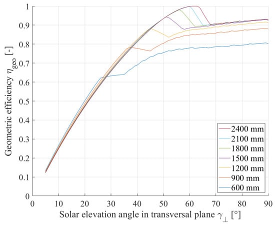
Figure 6.
Geometric efficiency of the considered Fresnel mirror field depending on elevation angle in transversal plane ; variation parameter is the receiver mounting height above mirror plane .
3.2. Mean Geometric Efficiency of Fresnel Mirror Concentrator
If the geometric efficiency in Figure 6 is averaged over the full range of transversal elevation angles , corresponding to all conditions that occur from sunrise to sunset in one day, the mean geometric efficiency can be calculated. Figure 7 illustrates this mirror field performance value as a function of the receiver height in the range from 600 mm to 2400 mm. The variation parameter in this graph is the side edge length of the square receiver cross section, varying between 50 mm and 250 mm. For an exemplary receiver height of 1200 mm, the mean geometric efficiency rises from 0.699 with a receiver side length of 250 mm to 0.757 for a receiver with a side length of 50 mm. The influence of the receiver size on the optical performance of the mirror field decreases with the growing receiver height , as the receiver shade only affects at high elevation angles for a reduced time duration of the day (see also Figure 6).
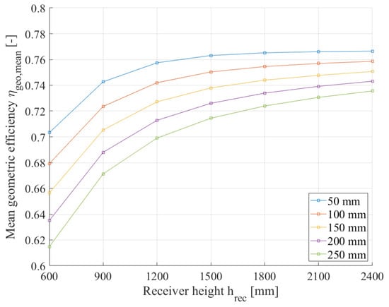
Figure 7.
Mean geometric efficiency of the mirror field depending on receiver height ; variation parameter is the side edge length of a square receiver cross section.
The mean geometric efficiency can be used to investigate further geometric dependencies within the mirror field. Figure 8 is valid for the given mirror field with 28 mirrors, a receiver height of 1500 mm and a receiver side edge length of 150 mm, and shows as a function of the mirror gap . The variation parameter in this figure is the mirror width , which ranges from 50 mm to 90 mm. The trends of this graph reveal that wider mirrors lead to reduced because the internal shading increases due to an enlargement in the mirror field width and steeper mirror angles. On the other hand, an increase in the mirror gap of up to 20 mm reduces the shading influences and improves , with a clear tendency for mirror widths of 50 mm and 60 mm. For mirror widths of 80 mm and 90 mm, this upward trend is less obvious, as are other influences like the receiver shading affect . If is 70 mm, shows a maximum of 0.742 at a mirror gap of 15 mm.
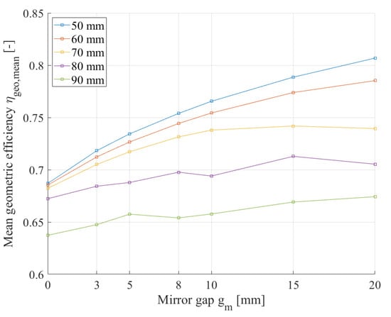
Figure 8.
Mean geometric efficiency of the mirror field depending on the mirror gap ; variation parameter is the mirror width .
3.3. Local Irradiance and Mean Irradiance in the Receiver Input Plane
Based on the modelling of the internal shading mechanisms and the consideration of the cosine losses, the developed optical model yields the resulting irradiance conditions in the receiver input plane, for the given input parameters of longitude, latitude, date, time and . The required model input parameters of the mirror width and mirror gap , which are 70 mm and 10 mm, respectively, are taken from the present Fresnel mirror concentrator (see Figure 1 and Table 1). The mounting height of the receiver is assumed to be 1500 mm, whereas the receiver cross section is defined by a dimension of 150 mm × 150 mm. With these premises, Figure 9 provides the local irradiance as a function of the x-position on the receiver input plane, where the centre of the receiver is defined by = 0 mm. The stepwise increase in starting at = −42.6 mm is related to the different widths of the focus images from the separate mirrors that overlap on the receiver input plane with different intensities . The beams of the outer mirrors impinge on the receiver at a flat angle, resulting in a wider image on the receiver, while the beams of the inner mirrors are reflected at a steep angle, leading to a smaller image. The modelling performed for the location of Wels, Austria, on 21 July at 16:00 CET, with an assumed of 500 W/m2, results in a maximum local irradiance of 11.3 kW/m2. The mean irradiance , calculated for the focus image width of 70.6 mm on the receiver input plane, is 8.33 kW/m2. The maximum value of can be detected at 10:45 CET and 13:35 CET, where the focus image on the receiver input plane has a width of 82.9 mm. This result is important for the subsequent design of the receiver prototype as a basis for choosing the appropriate dimensions of the input plane.
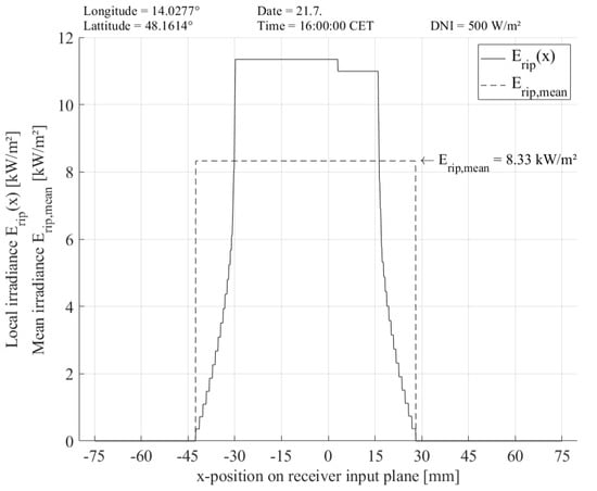
Figure 9.
Local irradiance and mean irradiance for the location of Wels, Austria, on 21 July at 16:00 CET, with a DNI of 500 W/m2.
3.4. Mean Irradiance in the Receiver Input Plane and Total Radiant Flux Depending on Time
By using the same input parameters for the optical model as mentioned above in Section 3.3, such as the mirror width, mirror gap, mounting height and dimensions of the receiver cross section, the optical performance of the considered Fresnel mirror field can be calculated depending on the time on a specific day. In this case, was measured using a pyrheliometer on the rooftop of the University of Applied Sciences Upper Austria in Wels, Austria, on 18 June 2021. The resulting graph in Figure 10 reveals the values of the mean irradiance from 5.32 kW/m2 at 06:00 to 15.42 kW/m2 at 12:00. The real concentration factor rises from 9.37 at 06:00 to a maximum value of 18.77 at 15:00. The decrease in and between 09:00 and 10:00 can be explained by the effect of the receiver shadow entering the mirror field. These characteristics correlate with the results of in Figure 6, which is reduced at a transversal elevation angle of > 50° for = 1500 mm. In the considered case of Figure 10, the angle exceeds the value of 50° between 09:00 and 10:00, leading to the observed reduction in the optical performance.
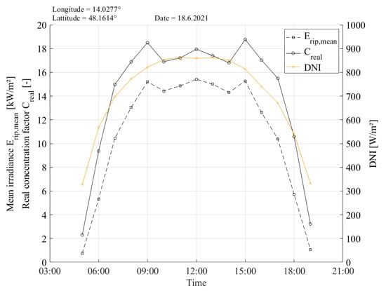
Figure 10.
Mean irradiance , real concentration factor and measured for the location of Wels, Austria, on 18 June 2021.
Besides the mean irradiance, the resulting total radiant flux is also an important outcome of the model, as this is the basis for calculating collector efficiencies after performance measurements with a CPVT receiver prototype. Figure 11 illustrates on the receiver input plane of the investigated concentrator system during the day of 18 June 2021, in Wels, Austria. A receiver length of 1.5 m is considered for this calculation. Starting from 06:00 in the morning, the total radiant flux impinging the receiver increased from 0.35 kW to 1.88 kW at 12:00.
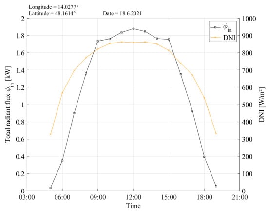
Figure 11.
Total radiant flux and measured for the location of Wels, Austria, on 18 June 2021.
3.5. Validation of the Optical Model
To validate the developed optical model and for a subsequent implementation of a receiver prototype, the Fresnel mirror field that is currently under study, as displayed in Figure 1, was equipped with a receiver carrier structure (see Figure 12a). The utilised aluminium profiles make it possible to steplessly adjust the receiver mounting height . Based on the results of the geometric efficiency calculation, as illustrated in Figure 6, was chosen with 1500 mm to perform the validation. In this configuration, yields satisfying values, and the entire handling of the future receiver prototype is expected to be free of risk at such a mounting height. The required focus re-alignment was performed in an experimental way, as described in detail in [25], via the mechanical adjustment of each mirror stripe.
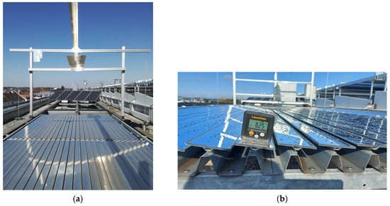
Figure 12.
Validation of the model results using the Fresnel mirror field at the University of Applied Sciences Upper Austria in Wels, Austria. (a) Receiver carrier structure implemented above the mirror field; (b) measurement of mirror angles using a precise goniometer.
With this adjusted mirror field, defined receiver mounting height and tracking control unit, the validation of the optical model was carried out by comparing the measured angle of each mirror stripe with the calculation results of the model. The angle measurement was performed using a goniometer, Laserliner MasterLevel Box Pro, with an accuracy of ±0.1° (see Figure 12b). Table 2 shows the results of this comparison, obtained for a transversal elevation angle of 90°. The longitudinal axis of the mirror concentrator is aligned to the north–south direction, and therefore, the mirror numbers 1 to 14 represent the western half of the mirror field, while mirrors 15 to 28 are located on the eastern half. The calculated mirror angles are symmetrical to the centre line of the mirror field, because = 90°. The deviation results in columns 4 and 8 yield the correlation between the calculated and the measured mirror angles and are coloured based on the following rules:
Table 2.
Comparison of calculated and measured mirror stripe angles for the present Fresnel concentrator at the University of Applied Sciences Upper Austria in Wels, Austria.
- Deviation < ±0.3°—very good correlation, coloured in green;
- Deviation ≤ ±1°—medium correlation, coloured in orange;
- Deviation > ±1°—insufficient correlation, coloured in red.
Using these chosen boundaries, 20 of the 28 mirror angles show a good correlation between the calculation and measurement, representing 71.4% of all mirrors. A total of 7 of the 28 mirror angles have a deviation of up to ±1°, and mirror 17 displayed the highest deviation of 1.5°. This comparison reveals that there is no tendential mismatch between the measured and calculated mirror angles, but the deviations are quite irregular. The mirrors of the western half correlate very satisfyingly, whereas the eastern mirrors diverge more, which leads to a missing symmetry of the measured angles to the centre line. Moreover, the measured angle of mirror 17 is almost equal to the one of mirror 16, which can only be explained by an inaccuracy in the experimental mirror alignment [25].
4. Discussion
The outcomes of the developed optical model for a Fresnel mirror concentrator can be evaluated as being very useful, on the one hand, for continuing the development of a CPVT receiver for the mirror field under study. On the other hand, the model can also be applied when optimising the geometrical arrangement of any other Fresnel mirror concentrator.
The calculation of , depending on the transversal solar elevation angle, clearly visualises one of the disadvantages of linear Fresnel mirror systems, that the available mirror surface is only partly illuminated most of the day, which is caused by internal shading effects. The developed model addresses these shading losses by computing , and therefore, the influence of geometrical modifications can be quantified. For the present Fresnel mirror field with the given number of mirrors and defined mirror gaps, the effect of the receiver mounting height on the optical performance is the most relevant for further work. Based on Figure 6, the future CPVT receiver prototype will be mounted at a height of 1500 mm above the mirror plane, where reaches a maximum of 0.944 at a transversal elevation angle of 51°. This chosen is a compromise between the geometric efficiency and practical accessibility of the receiver prototype during the future experimental phase.
The results of , as displayed in Figure 7, meet the expectation that the optical performance will improve with higher receiver mounting heights and with smaller receiver cross sections. However, as mentioned above, the optical model provides the possibility to quantify the impact of these two factors. For an exemplary of 1200 mm, a comparison of the receiver side edge lengths 50 mm and 250 mm results in a reduction in the active mirror surface by 6 percentage points, which is directly linked to a loss in the output power and energy of a future CPVT collector system. The investigated dependency of on the mirror width and mirror gap , as depicted in Figure 8, is relevant for the design of future mirror fields in order to maximise the optical performance. For the Fresnel concentrator under study with a mirror width of 70 mm and a mirror gap of 10 mm, the model results show that is close to the maximum of 0.742 in this geometrical arrangement.
The model outcomes in terms of the local and mean irradiance in the receiver input plane, presented in Figure 9, also have high relevance for further work with such concentrator systems. Firstly, the width of the focus image is important for defining the required width of the receiver, which is also strongly linked to the coherence of and receiver dimensions, as already discussed. Secondly, the resulting irradiance is the fundamental information needed for assessing the possible thermal and electrical output parameters of a future CPVT receiver. The simulation of and the resulting concentration factor over a full day requires the information of the , either from measurements or from climate data sets. The results for the given Fresnel mirror field at the location of Wels, Austria on 18 June 2021, show a maximum of 15.42 kW/m2 and a maximum of 18.77. Interestingly, as illustrated in Figure 10, the impact of the receiver shading can be observed clearly, leading to a decrease in and , while the is still rising. Generally speaking, the path of these curves clearly show that it is hardly possible to specify a single characteristic value for the concentration factor of such a Fresnel mirror field, as it is steadily changing with the sun´s position. Based on the results of , the total radiant flux impinging the defined area of a future receiver can be calculated. As the planned prototype of a CPVT receiver for the Fresnel collector in Wels, Austria, will have a length of 1.5 m, the maximum radiant flux resulted in 1.88 kW at 12:00 on 18 June 2021 (see Figure 11). This outcome is the most relevant input information for subsequent modelling and experimental work.
As the measurement of the concentrated irradiance is challenging and complex, according to the investigations performed by the authors of [22], the validation of the developed optical model had to be limited to an assessment of the mirror angle calculation results. Unexpectedly, the comparison between the calculated and measured mirror angles reveals that the modelled results are more reasonable than the experimental ones, because the detected mismatches can only be explained by the insufficient mechanical alignment of the single mirror stripes. Nevertheless, the validation of the model can be appraised as positive, as 71.4% of the mirrors showed a very good correlation between the calculation and measurement.
5. Conclusions
The developed optical model yields important results for the further research work with the Fresnel mirror field that is currently under study at the University of Applied Sciences Upper Austria in Wels, Austria. The receiver mounting height of 1500 mm appeared to provide an appropriate balance between the geometrical efficiency and experimental operability during the subsequent prototype validation. The maximum width of the focus image was detected to be 82.9 mm on 21 July at 10:45 CET, which is essential information for defining the dimensions of the receiver´s cross section. Finally, the developed model yields the resulting irradiance and the total radiant flux in the receiver input plane, depending on the date, time, DNI and length of the receiver. Together with the DNI measurement data, these outcomes will be used for the characterisation of the future CPVT receiver prototype.
The structure of the model provides high flexibility, as all relevant parameters of a Fresnel mirror concentrator are defined as input variables, such as the number of mirrors, geometrical dimensions of the mirror field and the receiver size and position, among others. Therefore, the application of the model is not restricted to the specific Fresnel mirror field that is currently in use at the University of Applied Sciences Upper Austria, but it can be used to optimise the optical performance of any variant. In this way, the model can contribute to increase the yield of renewable and emission-free energy generated by concentrating solar systems.
Author Contributions
Conceptualisation, A.R. and R.H.; methodology, A.R.; software, A.R.; validation, R.H.; writing—original draft preparation, A.R.; writing—review and editing, R.H.; visualisation, A.R.; supervision, R.H.; project administration, R.H.; funding acquisition, A.R. All authors have read and agreed to the published version of the manuscript.
Funding
This work is supported by research subsidies granted by the Government of Upper Austria within the research projects “Methodenentwicklung für Energieflussoptimierung” (Development of Methods for Optimization of Energy Flows; Research Grant Wi-2017-450841/17) and “Comprehensive Energy Storage” (Research Grant Wi-2022-600132/7-Au).
Data Availability Statement
Not applicable.
Acknowledgments
Open Access Funding by the University for Continuing Education Krems, the University of Applied Sciences BFI Vienna and the University of Applied Sciences Upper Austria. Editing of the English language was performed by Douglas Vaught from the University of Applied Sciences Upper Austria.
Conflicts of Interest
The authors declare no conflict of interest.
References
- REN21. Renewables 2022 Global Status Report; REN21: Paris, France, 2022. [Google Scholar]
- Zenhäusern, D. PVT Wrap-Up—Energiesysteme mit Photovoltaisch-Thermischen Solarkollektoren; Energie Schweiz: Bern, Switzerland, 2017. [Google Scholar]
- Weiss, W.; Spörk-Dür, M. Solar Heat World 2022—Global Market Development and Trends 2021|Detailed Market Figures 2020; AEE: Gleisdorf, Austria, 2022. [Google Scholar]
- Luque, A.; Hegedus, S. Handbook of Photovoltaic Science and Engineering, 2nd ed.; John Wiley & Sons, Ltd.: Chichester, UK, 2011. [Google Scholar]
- Quaschning, V. Regenerative Energiesysteme|Technologie—Berechnung—Klimaschutz, 11th ed.; Hanser Verlag: München, Germany, 2022. [Google Scholar]
- Imenes, A.; Mills, D. Spectral beam splitting technology for increased conversion efficiency in solar concentrating systems: A review. Sol. Energy Mater. Sol. Cells 2004, 84, 19–69. [Google Scholar] [CrossRef]
- Mojiri, A.; Taylor, R.; Thomsen, E.; Rosengarten, G. Spectral beam splitting for efficient conversion of solar energy—A review. Renew. Sustain. Energy Rev. 2013, 28, 654–663. [Google Scholar] [CrossRef]
- Ju, X.; Xu, C.; Han, X.; Du, X.; Wei, G.; Yang, Y. A review of the concentrated photovoltaic/thermal (CPVT) hybrid solar systems based on the spectral beam splitting technology. Appl. Energy 2017, 187, 534–563. [Google Scholar] [CrossRef]
- Daneshazarian, R.; Cuce, E.; Cuce, P.M.; Sher, F. Concentrating photovoltaic thermal (CPVT) collectors and systems: Theory, performance assessment and applications. Renew. Sustain. Energy Rev. 2018, 81, 473–492. [Google Scholar] [CrossRef]
- George, M.; Pandey, A.; Rahim, N.A.; Tyagi, V.; Shahabuddin, S.; Saidur, R. Concentrated photovoltaic thermal systems: A component-by-component view on the developments in the design, heat transfer medium and applications. Energy Convers. Manag. 2019, 186, 15–41. [Google Scholar] [CrossRef]
- Han, X.; Tu, L.; Sun, Y. A spectrally splitting concentrating PV/T system using combined absorption optical filter and linear Fresnel reflector concentrator. Sol. Energy 2021, 223, 168–181. [Google Scholar] [CrossRef]
- Huang, G.; Wang, K.; Curt, S.R.; Franchetti, B.; Pesmazoglou, I.; Markides, C.N. On the performance of concentrating fluid-based spectral-splitting hybrid PV-thermal (PV-T) solar collectors. Renew. Energy 2021, 174, 590–605. [Google Scholar] [CrossRef]
- Wang, K.; Pantaleo, A.; Herrando, M.; Faccia, M.; Pesmazoglou, I.; Franchetti, B.M.; Markides, C. Spectral-splitting hybrid PV-thermal (PVT) systems for combined heat and power provision to dairy farms. Renew. Energy 2020, 159, 1047–1065. [Google Scholar] [CrossRef]
- Stanley, C.; Mojiri, A.; Rahat, M.; Blakers, A.; Rosengarten, G. Performance testing of a spectral beam splitting hybrid PVT solar receiver for linear concentrators. Appl. Energy 2016, 168, 303–313. [Google Scholar] [CrossRef]
- Resch, A.; Höller, R. Design Concepts for a Spectral Splitting CPVT Receiver. In EuroSun2020 Conference; Charalambides, A., Streicher, W., Mugnier, D., Eds.; ISES: Freiburg, Germany, 2020; p. 12. [Google Scholar] [CrossRef]
- Resch, A.; Höller, R. Electrical Efficiency Increase in CPVT Collectors by Spectral Splitting. Energies 2021, 14, 8128. [Google Scholar] [CrossRef]
- Resch, A.; Thalhammer, T.; Angerer, P.; Daborer-Prado, N. Triethylenglycol as Novel Heat Transfer Fluid for CPVT Collectors with Spectral Splitting. In ISES Solar World Congress 2021; ISES: Freiburg, Germany, 2021; p. 12. [Google Scholar] [CrossRef]
- Boito, P.; Grena, R. Optimization of the geometry of Fresnel linear collectors. Sol. Energy 2016, 135, 479–486. [Google Scholar] [CrossRef]
- Widyolar, B.; Jiang, L.; Ferry, J.; Winston, R.; Kirk, A.; Osowski, M.; Cygan, D.; Abbasi, H. Theoretical and experimental performance of a two-stage (50X) hybrid spectrum splitting solar collector tested to 600 °C. Appl. Energy 2019, 239, 514–525. [Google Scholar] [CrossRef]
- Boito, P.; Grena, R. Application of a fixed-receiver Linear Fresnel Reflector in concentrating photovoltaics. Sol. Energy 2021, 215, 198–205. [Google Scholar] [CrossRef]
- Montenon, A.C.; Santos, A.V.; Collares-Pereira, M.; Montagnino, F.M.; Garofalo, R.; Papanicolas, C. Optical performance comparison of two receiver configurations for medium temperature Linear Fresnel Collectors. Sol. Energy 2022, 240, 225–236. [Google Scholar] [CrossRef]
- Fernández-Reche, J.; Valenzuela, L.; Pulido-Iparraguirre, D. Measuring Concentrated Solar Radiation Flux in a Linear Fresnel-Type Solar Collector. Solar 2022, 2, 401–413. [Google Scholar] [CrossRef]
- Wang, G.; Zhang, Z.; Chen, Z. Design and performance evaluation of a novel CPV-T system using nano-fluid spectrum filter and with high solar concentrating uniformity. Energy 2023, 267, 126616. [Google Scholar] [CrossRef]
- Mertins, M. Technische und Wirtschaftliche Analyse von Horizontalen Fresnel-Kollektoren. Ph.D. Thesis, Universität Karlsruhe, Karlsruhe, Germany, 2009. [Google Scholar]
- Resch, A.; Aigenbauer, T. On-site focus alignment of a fresnel mirror field. Renew. Energy Environ. Sustain. 2021, 6, 26. [Google Scholar] [CrossRef]
- DIN 5034 Part 2; Tageslicht in Innenräumen. Beuth: Berlin, Germany, 1985.
- Mertens, K. Photovoltaik—Lehrbuch zu Grundlagen, Technologie und Praxis, 4th ed.; Hanser Verlag: München, Germany, 2018. [Google Scholar]
- Häberlin, H. Photovoltaics—System Design and Practice; John Wiley & Sons, Ltd.: Chichester, UK, 2012. [Google Scholar]
- Sengupta, M.; Habte, A.; Wilbert, S.; Gueymard, C.; Remund, J. Best Practices Handbook for the Collection and Use of Solar Resource Data for Solar Energy Applications, 3rd ed.; National Renewable Energy Laboratory: Golden, CO, USA, 2021. [Google Scholar]
- Hering, E.; Martin, R. Optik für Ingenieure und Naturwissenschaftler; Hanser Verlag: München, Germany, 2017. [Google Scholar]
- Meyberg, K.; Vachenauer, P. Höhere Mathematik 1, 6th ed.; Springer: Berlin/Heidelberg, Germany, 2001. [Google Scholar]
Disclaimer/Publisher’s Note: The statements, opinions and data contained in all publications are solely those of the individual author(s) and contributor(s) and not of MDPI and/or the editor(s). MDPI and/or the editor(s) disclaim responsibility for any injury to people or property resulting from any ideas, methods, instructions or products referred to in the content. |
© 2023 by the authors. Licensee MDPI, Basel, Switzerland. This article is an open access article distributed under the terms and conditions of the Creative Commons Attribution (CC BY) license (https://creativecommons.org/licenses/by/4.0/).