Abstract
Much attention has been paid to the optimized protection of microgrids (MGs) and active distribution networks (ADNs). However, the literature shows a research gap in proposing a hybrid scheme, utilizing the voltage-based and overcurrent-based relays, while the voltage relay characteristics are smartly selected. This study aims to address such a research gap. This article presents an optimal hybrid protection coordination method for ADNs and MGs. Considering that any system fault is associated with a voltage drop, a new protection method is formulated from voltage analysis under fault conditions. The proposed method is independent of the type, size, and location of distributed generation (DG) units, as well as the operation of the distribution system connected to the grid. This method uses only the local voltage to determine the relay’s tripping time and is a low-cost protection method, in addition to the directional overcurrent relays (DOCRs). Optimizing the voltage-based relay characteristics is one of the most important contributions, which leads to improving the protection system speed and its selectivity concerns. The effectiveness of the proposed method has been verified by several simulation tests performed on the medium voltage (MV) distribution system under different fault conditions and DG size and location. The simulation results show that the protection method has appropriate speed, and the protection settings could be independent of the operation modes/topologies and the locations of faults. The comparative results illustrate the advantages of the proposed hybrid protective scheme.
1. Introduction
The protection of distribution systems is one of the most important issues in microgrids (MGs), active distribution networks (ADNs), and smart grids (SGs) in the presence of distributed generations (DGs) [1,2]. The advantages of DGs and distributed energy resources (DERs), e.g., the reduction of energy losses, improvement of voltage, and increase of overall energy efficiency, lead to increasing deployment of these energy sources. However, different issues, such as the specifications of the distribution network, the capacity and output power of DGs, and various operation modes and configurations, cause some problems in the protection systems of ADNs, MGs, and SGs, which disturbs the coordination of conventional overcurrent-based protection schemes [3]. Hence, several research works have been done in the literature about the optimal protection of ADNs, MGs, and SGs to mitigate the challenges.
Most of the studies in the literature have focused on overcurrent-based schemes. However, it should be noted that in ADNs and MGs, when a fault occurs, the short circuit current might not be much different from the load current due to operating in island mode, long-distance distribution lines, or high-impedance faults. Hence, the current-based protection methods do not work well against all faults. This means that some faults are not detected correctly, or the operation time for directional overcurrent relays (DOCRs) and the speed of the protection scheme would not be desired. Some methods have tried to modify the conventional overcurrent-based protection schemes to mitigate the discussed challenges in ADNs and MGs. However, the literature shows that only using the overcurrent-based protection scheme might not be effective for all cases. Accordingly, some methods have been reported based on voltage characteristics and other concepts.
In [4], for the protection of ADNs in the presence of scattered production sources, DOCRs with dual adjustment characteristics were used, which could work in both forward and reverse directions. The use of this type of relay causes better coordination and reduction of their operation time in distribution systems. Also, the suggested relay curves can perform the function of two DOCRs. But the most important problem with these types of relays was their programming, which optimized the operation time of the relays, and also, the use of these relays incurs additional costs. In [5], the firefly algorithm was used to coordinate the main and backup relays, and time and current settings were optimized and assigned to relays. The disadvantage of using this algorithm was that the trial and error method was used to coordinate the relays. On the other hand, this work increased the depreciation of electrical equipment in ADNs, and a large number of repetitions were needed to obtain optimal conditions. Reference [6] has investigated the high penetration of electronically coupled DERs in emerging distribution systems. Strezoski et al. [7] declared that the fault currents of these DERs could be limited to around twice their rated values after a short transient period. However, during the transient period, these currents might not be limited and could reach up to five times their nominal values. This phenomenon can cause the wrong set of protection devices and jeopardize the safety of the entire system. In addition, this paper studied the problems related to relay protection regulation caused by neglecting the transient side fault currents of electronically coupled DERs and offered suggestions to solve these problems.
The main goal of DOCR coordination in [8] was to find the optimal time dial setting (TDS) and pickup multiplier setting (PMS) to achieve the minimum total operation time of all primary relays subject to coordination constraints. Due to the complexity of the mixed integer non-linear programming problem (MINLP), the Imperial Competition Algorithm (ICA) was used as a powerful evolutionary algorithm to solve the coordination problem.
In [9], the main performance of protective equipment has been investigated, which provided an acceptable security capability. This study has studied the placement of DOCRs in the best location to keep the healthy parts working and only the faulty parts to be cut off quickly. This problem included many limitations, while various single-objective algorithms were proposed. Relay settings were defined as decision variables for this optimization problem. Also, a gray wolf optimizer (GWO), an improved version of the gray wolf optimizer (EGWO), a whale optimization algorithm, a hybrid whale-gray wolf optimizer (HWGO), an equilibrium optimizer (EO), and a direction algorithm Flow direction (FDA) were used to solve the optimization problem. The effectiveness and feasibility of the proposed techniques were evaluated using different networks and compared with other methods. Reference [10] presented a protection scheme based on an algorithm called tunicate swarming. This algorithm simulated crowd navigation movement and searcher behaviors. The proposed protection system was used to coordinate distance relays and DOCRs. In this plan, a protection system with eight buses has been investigated. In addition, to validate this plan, a comparison has been made with other algorithms. This comparison has led to the observation of many advantages of this plan over other plans. In [11], it has been stated that due to the change in the operation pattern from the position of grid-connected mode to the islanded one, significant and frequent fluctuations might be created compared to the short current position in the MGs. In this study, the optimization of the time multiplier settings (TMSs) of overcurrent relays was done to deal with the coordination problem. The particle swarm optimization (PSO) algorithm was also used. Moreover, the limitations of the industrial relay were stated by Senapati et al. [11]. According to reported studies in [12], the charging/discharging stations, the main load, and the power supply in the network change the structure of the distribution network. In addition to these issues, the amount and direction of the electric current are also effective and lead to a decrease in sensitivity and a change in system reliability. The discussed impacts on the protection systems have been studied by Wang et al. [12]. The proposed methods for detecting emergency states were suitable for implementation in smart electronic devices such as relays in digital substations. Reference [13] reported hardware-in-the-loop (HIL) testing for protective relays using a sample distribution system using the real-time digital simulator (RTDS). To perform this test, two SEL-351 relays were used, and the appropriate settings for the relays were calculated for coordination. In addition, how to configure the relay and other RTDS components that are critical for connecting the relay with the RTDS has also been investigated. The test was performed during three periods before the occurrence of the fault, during the fault, and after the fault. The results obtained from these analyses were checked against the event history of two SEL-351 relays obtained with the AcSELerator Quickset software. In [14], the proposed scheme based on an intelligent protection system for MGs has been presented. An adaptive meta-heuristic algorithm was used to automatically calculate the optimal settings for DOCRs. For this purpose, the adaptive fuzzy directional bat algorithm (AFDBA) related to the fuzzy inference system (FIS) has been used. The advantage of this method compared to other existing methods is that there is no need to initialize the parameters of the algorithm.
The protection system based on the communication link between the DOCRs and the control center was presented in [15]. In [16], it has been shown how false data injection attacks (FDIAs) affect the adaptive protective schemes of MGs. The DOCRs in the CIGRE low voltage (LV) benchmark test system have been studied. Some experiments and studies have been done for the manipulation of protection decisions, considering cyber attacks. The introduced study was verified on commercial relays using a simultaneous digital simulator. Azari et al. [17] studied the communication links to increase the performance of the optimal coordination of DOCRs. These relays have been assumed to be equipped with a communication link on both sides of the line to increase the speed of operation during a fault. This communication link causes complete coverage of the line by distance relays. The number and place of installation of the communication link have a great influence on the operation time of DOCRs and the distance relays and coordination between them. The coordination problem has been formulated, considering the location and number of communication links. The GA and LP have been used to solve the introduced optimization problem. Using the GA, the location and setting of the second zone of the distance relay as well as LP, was used to set the DOCRs. In the method presented by Coffele et al. [15], after every change in the topology of the ADNs and MGs, the relays’ settings were calculated and assigned to DOCRs. In [18], an overcurrent-based protection method for ADNs and MGs has been mentioned, utilizing communication links between DOCRs. This method did not work well in high impedance faults and faults that are far from the relevant relay and caused malfunction and miscoordination in the reported protection system.
In [19,20], the fault current limiters (FCLs) for the control and reduction of the fault current of distributed generation soDGs/DERs have been studied. FCL reduces the amount of short-circuit current against faults and maintains the coordination between the main and backup relays [21]. The resistance/reactance value of FCLs is zero in the normal state. When there is a fault in ADNs and MGs, their resistance/reactance value increases rapidly and reduces the fault current [22]. The most important advantage of this method is the possibility that the system returns to normal after a short circuit. The main weakness of this solution is the voltage drop in the operating mode of the distribution systems when there is a fault because the fault resistance has increased [23].
The literature review shows that much attention has been paid to the protection of MGs, ADNs, and SGs. Also, several studies have focused on DOCRs and overcurrent-based approaches for MGs and ADNs. Although different advantages have been achieved through applying the introduced overcurrent-based protective approaches, it seems the introduced approaches could not comprehensively mitigate the challenges corresponding to low short-circuit currents due to MGs behaviors. This is one of the main motivations for developing other protective schemes using voltage features or other technical frameworks.
In [24], a protection scheme of ADNs with DGs/DERs has been studied, where the reclosers have been coordinated with the downstream fuses. In this protection method, short-circuit voltage and current, time setting, and two other variables were used. When a fault occurs near the reclosers, the DGs/DERs do not have much effect on the fault current. But in far faults, the fault current passing through the protective devices changes greatly and causes miscoordinations and malfunctions. In the reported scheme, in addition to the fault current, the voltage drop of each phase has been used to coordinate the protective devices. Because the fuses react to transient faults and issue a disconnection order, the operating/not-operating of fuses against transient faults has been prevented, and the network could be prevented from shutting down untimely. This proposed method was low-cost and did not require communication links. The discussed protection method has been tested for medium voltage (MV) ADNs. This type of protection could play an important role in distribution systems because it performs well under different impedances and small and large faults. Reference [24] has tried to optimize the protection coordination of these types of relays, which reduces the operation time of all network relays. The DIgSILENT software has been used to simulate the ADNs, and MATLAB software has been used to optimize the operation time of the relays. In [25], a user-defined dual-directional overcurrent relay with combined current-time-voltage characteristics (UDDOR-TCV) was proposed to enhance the flexibility of the proposed design without any communication aid for radial ADNs/MGs and their relays.
According to [26], the proposed method was based on non-linear constraints such as time adjustment, fault current, fault voltage, and two other variables. This method required relay voltage drop and fault current as the input signal. The introduced optimization problem in [26] has been solved using a differential evolutionary algorithm. It has been shown that the tripping time of the main and backup relays would be reduced by applying the introduced method. Due to the insignificant fault current in solar-based energy systems, this method was very effective, and the operation time of the relays was much less than conventional protective schemes. The disadvantage of this method was that with a small increase in the load current and a small voltage drop, the relay operated. It might recognize and apply the load inrush current as fault current, which was not appropriate for the system. On the other hand, five variables have been used to formulate the relay, which was difficult to plan for their optimization. The addition of DGs/DERs, especially photovoltaic (PV) units, led to changes in grid topology and fault currents. Under normal network conditions, conventional step-down relays might not distinguish load current and fault current from each other and cause malfunctions in systems. Conventional sag relays under normal network conditions might not distinguish load current and fault current from each other and cause non-desired conditions in ADNs. This coordination problem has been investigated by developing a conventional step-by-step relay and a new method has been proposed [27]. In the introduced study, the relay current and voltage settings were optimized within a non-linear optimization problem by the genetic algorithm (GA) (one of the well-known optimization algorithms in the field of protection systems of ADNs and MGs [28]) and also time settings were found, using liner programming (LP) [29]. The advantage of this method was reducing the number of variables due to the use of hybrid optimization programs and also improving the convergence of the algorithm. In [30], the GA and LP were used simultaneously to optimize the decision variables of the proposed method, which reduced the operating time of relays compared to existing studies. However, their programming was very difficult. When a fault occurs, the short circuit current range changes from zero to several kiloamperes, and when the impedance is high, the voltage is greatly reduced, and the faults are not well detected, causing malfunctions in the protection system and some miscoordination in ADNs and MGs. Therefore, the reported method in [6] has been used to protect the network by overcurrent relays. The topology of the network may change due to possible outages of the lines in real conditions, which will change the level of short circuits in all the buses of the network. Therefore, to coordinate the relays, topological changes in the network must be considered. In [31], sequential quadratic programming (SQP), which is also available in the MATLAB software toolbox, was used to solve the optimization problem for the protection of power systems. In the formula presented in [32], the fault current has been used for the operation time of the relays. The variables of the proposed method in [32] were not optimized. Hence, the operation times of the relays were slow. In [33], a new protection method for ADNs using short-circuit voltage measurement was presented. The most important advantage of this protection method was that against far faults, the relays detect the fault well and isolate the faulty area properly. Reference [33] is one of the most effective studies in the literature in the viewpoint of speed and performance against far faults dn those faults with insignificant short-circuit currents. The curve types of the suggested voltage-based characteristics have not been optimized, in addition to other settings. Moreover, the hybrid protective schemes, using the suggested voltage-based relays and conventional DOCRs, have not been examined in [33]. Ebrahimi et al. [34] reported an energy not-supplied (ENS)-oriented protection scheme based on voltage characteristics. The inverter-based DGs (IBDGs) have been studied in [34], while the voltage index has been introduced to mitigate the system challenges.
In some research works, some new protective schemes based on distance and differential relaying concepts have been reported for ADNs, MGs, and SGs [35,36]. For instance, Martin et al. [37] have proposed distance protection for ADNs. However, these schemes might not be practical because of their required investments and additional hardware and software infrastructures. The short length and the high number of lines, as well as the effect of current changes caused by the connection or non-connection of scattered production sources, etc., on the performance of the installed distance relays, will lead to a change in the impedance seen by the relay. This issue leads to an adverse effect on the protection systems based on distance relays. Therefore, the use of distance relays is not operational in distribution networks. In [38], the differential protection method for distribution systems was presented. For several reasons, including a large number of distribution lines and the short length of most of the lines in these networks, as well as the need to connect current transformers on both sides of the line, this proposed plan would have challenges. In this reference, voltage and short-circuit currents for single-phase, two-phase, and three-phase faults were used in different locations of the feeder for the operation time of the main and backup relays, which was to minimize the operation time. The simulation results in [38] showed that overcurrent relays in the network work well only for near faults, and this protection method did not work well for far faults. In [39], the progress of digital relay protection developments and modern automation was studied. It has been noted that one of the promising ways to develop protection and control systems is to develop new basic algorithms for emergency detection. The studied algorithms by [39] controlled a large number of characteristics or state parameters (current, voltage, resistance, and voltage phase). Therefore, algorithms were multi-dimensional. In addition, classic machine learning algorithms were used in their relay protection algorithm, especially the k-methods algorithm, as well as nearest neighbor methods, logistic regression, and support vectors. The literature review illustrates that although new frameworks based on distance and differential relay concepts and other new features might be useful, they are exposed to some essential challenges in practical situations and implementation procedures. Accordingly, the simplified schemes, e.g., the voltage-based relay characteristics, could be more effective than such approaches.
Briefly, it should be declared, based on the literature review, that in ADNs, MGs, and SGs, sometimes the value of the fault current might not be very different from the load current. This condition appears due to being operated in the islanded mode, high-impedance faults, or long-distance distribution lines. Hence, the impedance-based and overcurrent-based approaches do not work well. Some challenges exist with this problem, and the faults might not be well detected, or the tripping time of relays is slow. In addition, the eventual miscoordination between the main and backup relays is another important restriction for overcurrent-based protection schemes that must be responded to by the developed solutions. The literature review illustrates that voltage-based protective solutions could be effective and easy to implement in practical conditions. On the other hand, although several approaches have been presented in the available research works for voltage-based schemes of MGs, ADNs, and SGs, there is a research gap in proposing a new hybrid voltage-based scheme equipped with DOCR-based relays, while the curve types of voltage-based relays are optimized and smartly selected. This study aims to fill such a research gap by extending the introduced approaches in [33] through a hybrid protective scheme and optimized voltage relay characteristics.
The main novelties and contributions of this study can be listed as follows:
- Proposing a hybrid protective scheme utilizing voltage-based and DOCR-based relays;
- The smart selection of voltage relay characteristics to improve the speed of the protection scheme and satisfaction of selectivity constraints;
- Desired performance of the proposed protective scheme against the low current faults due to various reasons.
The proposed hybrid protective scheme is applied to an actual MV ADN. The power flow, short-circuit voltage and current analyses, and other simulations are done in a DIgSILENT environment. Also, the optimization problem is solved using the GA in MATLAB. The test results illustrate the effectiveness and advantages of the proposed method compared to available ones.
2. Proposed Method
In the proposed protective scheme of ADNs and MGs, the DOCRs are used, in addition to new voltage relays. The operating time of DOCRs can be formulated using (1) [40,41].
In (1), t represents the operating time of DOCRs. Also, TMS is the time setting relays, and indicates the current setting. The curve type of DOCRs is distinguished by a and b coefficients. In (1), the values of and are pre-defined parameters based on standard relay characteristics, as presented in Table 1. In this study, the normal inverse (NI) curve type is selected for all DOCRs in the proposed protective scheme. The short-circuit current () is another essential parameter that is needed to determine the operating time of DOCRs. The normal current passing through the relay is indicated by , and the minimum allowed current setting of DOCRs has been shown by in (2).

Table 1.
Coefficients of relays.
The time and current settings of DOCRs should be determined by the designer of the protection system [42,43]. In the proposed hybrid protective scheme, both time and current settings ( and ) are optimized. In (2), the minimum allowed pickup current setting of DOCRs has been mathematically expressed. In some references, the time multiplier settings (TMSs) are not optimized, and they would be selected according to pre-defined values equal to (2). However, in this study to improve the speed of the protection system and facilitate the coordination constraint meeting, the current settings are also optimized.
In (3), it has been expressed that the total time differences between the backup and main relays () have been selected for the objective function (OF) of the proposed optimization problem. Also, i, n, , and represent the index of the main and backup relays pair, the total number of coordinated relay pairs, the operating time of the backup relay, and the operating time of the main relays, respectively. In addition, the time interval between the main and backup relays to meet the selectivity constraints is indicated by CTI. The main relay should have the highest operating speed and should not operate for faults outside its range. The backup relay must have a sufficient time delay for the main relay to isolate the fault [44]. The limitation of coordination of main and backup relays is expressed using (4). The minimum allowed coordination time interval (CTI) is considered to be 0.3–0.5 s.
In Equations (1) and (2), and are two essential current and time settings of DOCRs, which should be determined by the designers of the protection schemes of ADNs and MGs. In the proposed study, according to the lower and upper bounds, these decision variables and relay settings can be optimized based on (5) and (6). The upper bound of relays’ current settings is determined according to the minimum fault currents (). The discussed upper bound results in acting the dOCRs against all faults downstream of relays.
DOCRs do not recognize their far-end faults (faults with low short-circuit currents) well and disrupt the distribution system. Hence, the voltage relays, using the new relay characteristics in [33], are deployed in the proposed hybrid protective scheme. In (7) and (8), the selected voltage relay characteristic is presented.
The selected voltage relay characteristic has been defined according to the voltage of the relay during the short circuit and fault (). A parameter (k) has been used to evaluate the deviation of the voltage from the rated condition. Another parameter (m) has also been utilized in the proposed mathematical characteristic for voltage relays. The operating time of the voltage relay is represented by t in (8), while the TDS would be the time setting of these relays. The curve type is also a function of two coefficients (A and P). The additional delay can be assigned to the operating time of selected voltage relays using (D).
In (7) and (8), and are pre-defined parameters that are equal to 1 and 2, respectively. The D value represents the difference between the operation time of the main and backup relays, which can be changed from 0 to 0.08. When a fault occurs, because the short-circuit voltage range is between 0 and 1 p.u, short-circuit voltage changes are used to coordinate the main and backup relays, and according to this method, the relay can also see its remote faults and function well. The disadvantage of the proposed method is that and variables are not optimized, and the operation time of the relays is long. This research has tried to optimize the operation time of the relays at different points of the lines. To coordinate the relays according to the proposed formula (Equations (7) and (8)), the backup relay must have a time delay that does not interfere with the operation of the main relay. In terms of (5) and (6), using lower and upper bounds, we can optimize the two variables and by using the GA:
It should be clarified that voltage protection might be rarely used alone, especially in small-scale power grids, due to poor voltage discrimination. Hence, a hybrid protective scheme based on both voltage relays and DOCRs has been proposed in this article. Indeed, the advantages of both voltage and current-based frameworks are achievable by applying the proposed model.
In addition, it is difficult to apply current protection to dual-ended power lines, short lines, far-end faults, high-impedance faults, and so on. The directional relays should be used for meshed distribution networks and ADNs to mitigate the problems corresponding to the changes in the direction of short-circuit currents. Although the DOCRs are the most commonly used relays for ADNs and MGs, there are some challenges for this type of protection scheme. The proposed hybrid model facilitates the system to mitigate the discussed challenges.
A question might appear about the advantage of the distance relay-based models for ADNs and the proposed hybrid scheme. It should be noted that the distance relay based on simultaneous voltage and relay measurements can be useful. However, it is not easy to implement the distance relay in distribution networks. If the conventional distance relays that are used for high-voltage transmission networks were applied to ADNs, they would not be satisfying from an economic viewpoint. On the other hand, it is possible to implement new approaches based on distance relay concepts, particularly for ADNs. Indeed, the introduced distance protection schemes for ADNs and microgrids should be modified and more commercialized for these purposes. In addition to economic concerns, conventional distance relays and schemes using distance protection concepts may not be effective for protecting ADNs and MGs due to the structure of ADNs and multiple branches in these types of electrical systems, unlike transmission systems. The challenges of new protective approaches based on distance relays in the literature reviewer have also been tried and discussed. Therefore, the proposed hybrid scheme could be more practical than distance-based protection models for ADNs and MGs. However, in further future works, the proposed hybrid protection scheme can be equipped with distance relaying because the local measurements of voltage and current are achievable through the proposed approach.
3. Test Results and Discussions
To implement the proposed method, the medium voltage radial distribution system shown in Figure 1 has been used. This system is supplied by two 63/20 kV transformers, and YND1 connection, and 30 MW ampere power. The fault current level in the 63 kV bus is equal to 3.65 kA. The specifications of DGs have been presented in Table 2. The locations of the relays have been selected based on [33]. It should be noted that the allocation of relays (placement of protective relays), in addition to the optimized settings, is possible. However, if the system has been designed previously and is under operation, only the optimized settings could be used to improve the performance of the protection system. In general, it can be noted that to increase the system reliability in ADNs and MGs, the protective relays are placed in the closest position to the connection point of DGs. The presence of DGs in the network may cause faults such as sudden overcurrent or reverse current in the network. Therefore, the existence of any relay prevents the network from being damaged, which increases the system’s reliability. However, in further future research works, the simultaneous optimization of relays’ location and relay settings can be studied.
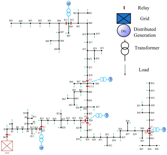
Figure 1.
Understudy MV distribution system [33].
Table 2.
Specifications of DGs.
This system is equipped with 13 relays, which are of an overcurrent type. DIgSILENT software has been used to perform load flow and short circuit analyses, and MATLAB software and GA have been used to optimize the operation time of the main and auxiliary relays.
Therefore, two scenarios are studied to examine the advantages of the proposed hybrid protective scheme:
- Scenario 1: In Scenario 1, the current-based protection is studied. The DOCRs are utilized to protect the ADNs and MGs against faults and short-circuit currents. The operating times of DOCRs in the current-based protective approach are determined using (1) and (2). As explained in the proposed method, the current and time settings of DOCRs ( and ) are decision variables, and they are optimized in this research. On the other hand, the relay curves have been selected from standard relay characteristics, and the NI curve type is assigned to all DOCRs in Scenario 1;
- Scenario 2: In Scenario 2, the proposed voltage-based protection scheme is investigated. The decision variables of the proposed optimization problem would be time setting and curve type coefficient of voltage relays ( and ). According to Equations (7), (8) and (10), the value of variable has been pre-defined in available references. However, in this study, the curve type coefficient () would be optimized in Scenario 2 by the GA in addition to time settings. Also, faults are created at different points, and the operation times of the main and backup relays and variable are examined.
In the following, a comparison is made between Scenarios 1 and 2 to evaluate the advantages of the current-based and voltage-based protective schemes. It can be seen that the voltage-based method is superior for far-end faults. Also, the advantages of optimization can be illustrated by the obtained results. Moreover, the proposed hybrid protection scheme operates against faults based on the advantages of both approaches.
According to the flowchart in Figure 2, all the stages of this research can be seen. First, network modeling was done, then the mathematical model of overcurrent protection was fully presented. Also, the coordination of overcurrent relays and their principles were explained. In the development of the proposed method, existing methods have been used to coordinate the protection of distribution networks.
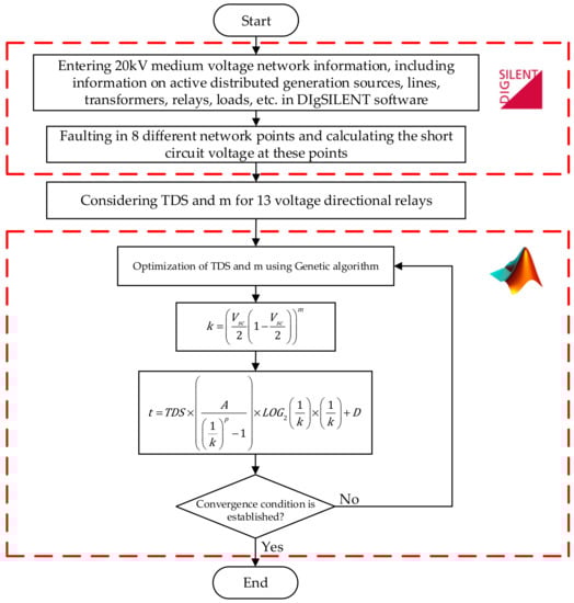
Figure 2.
Flowchart of the proposed voltage-based protection of ADNs.
4. Results
The results of and values, as well as the operation time of the relays before and after optimization, are given in Table 3 and Table 4.
Table 3.
Operation time of main and backup relays before optimization in the first scenario.
Table 4.
Operation time of main and backup relays after optimization in the first scenario.
The selectivity diagrams and coordination between the main and backup relays for different relays and faults are shown in Figure 3 and Figure 4.
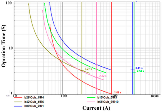
Figure 3.
The characteristic curve of operation time of main and backup relays before optimization in the first scenario.
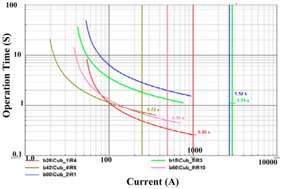
Figure 4.
The characteristic curve of operation time of main and backup relays after optimization in the first scenario.
According to the proposed methods based on (7) and (8), the operation time of the main and backup relays as well as the values of TDS and m have been optimized. In addition, in buses 5, 22, 34, 50, 44, 56, 73, and 93 in eight different fault scenarios have been done. Short-circuit voltage and variable k are stated in Table 5. In addition, Table 6 shows the values of backup relays for the proposed method in the second scenario before optimization. The optimized values for and have been presented in Table 7. Moreover, Table 8 shows and values for the proposed method after optimization in the second scenario.
Table 5.
The values of the main relays for the proposed method in the second scenario before the optimization.
Table 6.
The values of backup relays for the proposed method in the second scenario before optimization.
Table 7.
and values for the proposed method before optimization in the second scenario.
Table 8.
and values for the proposed method after optimization in the second scenario.
The proposed hybrid protective scheme based on voltage and current relay models improves the speed of the protection system. This improvement increases the reliability of the network and the lifetime of the equipment. Also, reducing the risks caused by not detecting far-end faults is another achievement of the proposed relaying model.
Furthermore, in Table 9, the values of the main relays for the proposed method in the second scenario after optimization are demonstrated. Also, Table 10 describes the values of backup relays for the proposed method in the second scenario after optimization.
Table 9.
The values of the main relays for the proposed method in the second scenario after optimization.
Table 10.
The values of backup relays for the proposed method in the second scenario after optimization.
Figure 5 shows the operation time of the relays in different , whose value can be changed between 0.1 and 1. According to the figure, as the value of tends to 1, the relay operation time decreases, and it operates faster. The operation time of the relay also depends on the short-circuit voltage, so the shorter the short circuit, it shows that the fault is near the relay, and therefore the relevant relay must operate quickly. As the short-circuit voltage increases, the relay operation time also increases. Fault-clearing time before and after optimization for typical relays and fault locations have been shown in Figure 6 and Figure 7. According to the comparison of the operation time of relays 9 and 10 in the fault, it shows that after optimization, the fault-clearing time is significantly reduced, and the network is less damaged. The fault-clearing time before the optimization is approximately 0.3 s, but after optimization, it is almost 0.04. This optimization is related to and done by the GA.
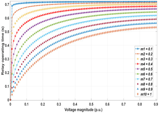
Figure 5.
Proposed voltage relay characteristic based on different curve type coefficients.
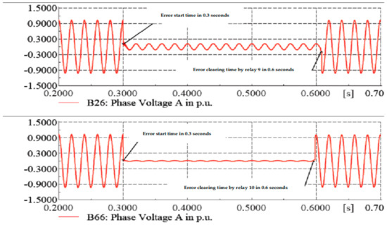
Figure 6.
Fault-clearing time before optimization.
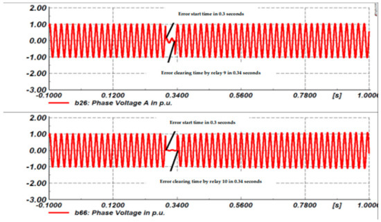
Figure 7.
Fault-clearing time after optimization.
To verify the reliability of the proposed scheme, which is one of the basic requirements of relay protection, it has been tried to verify some spatially similar points. The simulation results in DIgSILENT approved that the proposed hybrid scheme is adequately robust against the eventual malfunction.
Furthermore, it is useful to verify whether the protection malfunctions when the system operation mode is inconsistent, as there are significant differences in short-circuit current and system voltage under different operating states. Several studies have been done in the DIgSIELNt environment to evaluate the discussed technical challenges. The robustness of the proposed model is satisfying. However, further future works to improve the system performance from the viewpoint of these challenges are interesting and useful.
5. Conclusions
The literature review showed that a great deal of attention has been paid to the protection of ADNs and MGs. It has been reported that the overcurrent-based schemes might not be effective against all faults, particularly in islanded modes and far-end faults. Although several voltage-based approaches have been introduced in the literature, a research gap exists in proposing a hybrid protective scheme using voltage-based relays in addition to the conventional DOCRs. This paper has tried to respond to this gap. Smart selection of voltage relay curves, in addition to proposing a hybrid scheme, facilitated the speed up of the protection system and selectivity constraint satisfaction. The main findings of this study based on the obtained results can be listed as follows:
- The optimized relay settings of the DOCRs could effectively improve the speed of the protection system. The comparative test results showed that significant improvement in the operating time of DOCRs is achievable by applying the optimized time and current settings;
- The combination of voltage-based and overcurrent-based relays has improved the performance of the protection system against far-end and near-end faults;
- The comparative test results emphasized the importance of the smart selection of voltage relay curves/characteristics. The obtained results approved the declared novelties and advantages of the proposed study;
- The possibility of fault detection and clearing the faults by voltage relays was investigated using the proposed method of optimizing time settings and characteristic curve coefficients of less than 0.3 s. This tripping time of relays provides the ability to use the proposed scheme for complex networks with many coordination constraints.
The following further future research works to extend this study can be demonstrated:
- The time-current-voltage characteristics can be examined in the proposed hybrid protection scheme;
- Investigating the limitations of transient stability of synchronous generators in the protection scheme based on the proposed hybrid approach using the voltage relays and DOCRs;
- Using the FCLs to improve fault-clearing performance and examine the benefits of the proposed method based on voltage relays in the detection and protection of distribution networks.
Author Contributions
Conceptualization, H.H.-D.; methodology, A.V., M.A.H., H.H.-D. and N.M.; software, A.V., M.A.H. and H.H.-D.; validation, M.A.H. and H.H.-D.; formal analysis, A.V., M.A.H., H.H.-D. and N.M.; investigation, A.V., M.A.H., H.H.-D. and N.M.; resources, M.A.H. and H.H.-D.; data curation, A.V., M.A.H., H.H.-D. and N.M.; writing—original draft preparation, A.V., M.A.H., H.H.-D. and N.M.; writing—review and editing, M.A.H. and H.H.-D.; visualization, A.V., M.A.H., H.H.-D. and N.M.; supervision, M.A.H. and H.H.-D.; project administration, M.A.H. and H.H.-D.; funding acquisition, M.A.H. and H.H.-D. All authors have read and agreed to the published version of the manuscript.
Funding
This research received no external funding.
Data Availability Statement
Data available on request due to restrictions e.g., privacy or ethical.
Conflicts of Interest
The authors declare no conflict of interest.
References
- Ghadiri, S.M.E.; Mazlumi, K. Adaptive protection scheme for microgrids based on SOM clustering technique. Appl. Soft Comput. 2020, 88, 106062. [Google Scholar] [CrossRef]
- Ghotbi-Maleki, M.; Chabanloo, R.M.; Taheri, M.R.; Zeineldin, H.H. Coordination of non-directional overcurrent relays and fuses in active distribution networks considering reverse short-circuit currents of DGs. IET Gener. Transm. Distrib. 2021, 15, 2539–2553. [Google Scholar] [CrossRef]
- Azimi, A.; Hashemi-Dezaki, H. Optimized protection coordination of microgrids considering power quality-based voltage indices incorporating optimal sizing and placement of fault current limiters. Sustain. Cities Soc. 2023, 96, 104634. [Google Scholar] [CrossRef]
- Zeineldin, H.H.; Sharaf, H.M.; Ibrahim, D.K.; El-Zahab, E.E.-D.A. Optimal Protection Coordination for Meshed Distribution Systems With DG Using Dual Setting Directional Over-Current Relays. IEEE Trans. Smart Grid 2014, 6, 115–123. [Google Scholar] [CrossRef]
- Tjahjono, A.; Anggriawan, D.O.; Faizin, A.K.; Priyadi, A.; Pujiantara, M.; Taufik, T.; Purnomo, M.H. Adaptive modified firefly algorithm for optimal coordination of overcurrent relays. IET Gener. Transm. Distrib. 2017, 11, 2575–2585. [Google Scholar] [CrossRef]
- Petrovic, N.; Strezoski, L.; Dumnic, B.; Popadic, B. Relay protection challenges in distribution system with electronically coupled DERs. In Proceedings of the 12th Mediterranean Conference on Power Generation, Transmission, Distribution and Energy Conversion (MEDPOWER 2020), Online, 22 September 2021; Volume 2020, pp. 154–159. [Google Scholar] [CrossRef]
- Strezoski, L.; Stefani, I.; Bekut, D. Novel method for adaptive relay protection in distribution systems with electronically-coupled DERs. Int. J. Electr. Power Energy Syst. 2020, 116, 105551. [Google Scholar] [CrossRef]
- Alaee, P.; Amraee, T. Optimal Coordination of Directional Overcurrent Relays in Meshed Active Distribution Network Using Imperialistic Competition Algorithm. J. Mod. Power Syst. Clean Energy 2021, 9, 416–422. [Google Scholar] [CrossRef]
- Korashy, A.; Kamel, S.; Shahinzadeh, H.; Kabalci, E.; Jurado, F. Different Optimization Techniques For Solving the Coordination problem of DOCRs. In Proceedings of the 2022 4th Global Power, Energy and Communication Conference (GPECOM), Cappadocia, Turkey, 14–17 June 2022; pp. 499–505. [Google Scholar] [CrossRef]
- Abdelhamid, M.; Kamel, S.; Nasrat, L.; Shahinzadeh, H.; Nafisi, H. Adaptive Coordination of Distance and Direction Overcurrent Relays in Active Distribution Networks Based on the Tunicate Swarm Algorithm. In Proceedings of the 2022 12th Smart Grid Conference (SGC), Kerman, Iran, 13–15 December 2022; pp. 1–6. [Google Scholar] [CrossRef]
- Senapati, M.; Panigrahi, P.K.; Ray, P.K.; Mohanty, A. Optimal Relay Coordination and optimization in Distributed generation based Power System. In Proceedings of the 2022 IEEE 2nd International Symposium on Sustainable Energy, Signal Processing and Cyber Security (iSSSC), Gunupur, Odisha, India, 15–17 December 2022; pp. 1–6. [Google Scholar] [CrossRef]
- Wang, Q.; Ma, J.; Shang, L.; Chen, S. Analysis of the Effects of Grid-Connected Charging/Discharging Stations on Relay Protection. Energies 2022, 15, 9065. [Google Scholar] [CrossRef]
- Yadav, G.; Liao, Y.; Burfield, A.D. Hardware-in-the-Loop Testing for Protective Relays Using Real Time Digital Simulator (RTDS). Energies 2023, 16, 1039. [Google Scholar] [CrossRef]
- Sampaio, F.C.; Tofoli, F.L.; Melo, L.S.; Barroso, G.C.; Sampaio, R.F.; Leão, R.P.S. Smart Protection System for Microgrids with Grid-Connected and Islanded Capabilities Based on an Adaptive Algorithm. Energies 2023, 16, 2273. [Google Scholar] [CrossRef]
- Coffele, F.; Booth, C.; Dysko, A. An Adaptive Overcurrent Protection Scheme for Distribution Networks. IEEE Trans. Power Deliv. 2015, 30, 561–568. [Google Scholar] [CrossRef]
- Gutierrez-Rojas, D.; Demidov, I.; Kontou, A.; Lagos, D.; Sahoo, S.; Nardelli, P.J. Operational Issues on Adaptive Protection of Microgrids due to Cyber Attacks. IEEE Trans. Circuits Syst. II Express Briefs 2023, 1. [Google Scholar] [CrossRef]
- Azari, A.; Noghabi, A.S.; Zishan, F.; Montoya, O.D.; Molina-Cabrera, A. Evaluating the Effect of the Communication Link of the Relays on the Operation Time of the Protection System. Energies 2023, 16, 2692. [Google Scholar] [CrossRef]
- Farkhani, J.S.; Zareein, M.; Soroushmehr, H.; Sieee, H.M. Coordination of Directional Overcurrent Protection Relay for Distribution Network With Embedded DG. In Proceedings of the 2019 5th Conference on Knowledge Based Engineering and Innovation (KBEI), Tehran, Iran, 28 February–1 March 2019; pp. 281–286. [Google Scholar] [CrossRef]
- Wheeler, K.; Elsamahy, M.; Faried, S. Use of superconducting fault current limiters for mitigation of distributed generation influences in radial distribution network fuse–recloser protection systems. IET Gener. Transm. Distrib. 2017, 11, 1605–1612. [Google Scholar] [CrossRef]
- Rebizant, W.; Solak, K.; Brusilowicz, B.; Benysek, G.; Kempski, A.; Rusiński, J. Coordination of overcurrent protection relays in networks with superconducting fault current limiters. Int. J. Electr. Power Energy Syst. 2018, 95, 307–314. [Google Scholar] [CrossRef]
- Usama, M.; Mokhlis, H.; Mansor, N.N.; Moghavvemi, M.; Akhtar, M.N.; Bajwa, A.A.; Awalin, L.J. A multi-objective optimization of FCL and DOCR settings to mitigate distributed generations impacts on distribution networks. Int. J. Electr. Power Energy Syst. 2023, 147, 108827. [Google Scholar] [CrossRef]
- Wang, R.; Liao, M.; Duan, X.; Xie, D.; Feng, Z.; Han, X. Development and parameters optimization of a self-driving fault current limiter. Electr. Power Syst. Res. 2023, 218, 109187. [Google Scholar] [CrossRef]
- Sadeghi, M.H.; Dastfan, A.; Damchi, Y. Optimal coordination of directional overcurrent relays in distribution systems with DGs and FCLs considering voltage sag energy index. Electr. Power Syst. Res. 2021, 191, 106884. [Google Scholar] [CrossRef]
- Jamali, S.; Borhani-Bahabadi, H. Recloser time–current–voltage characteristic for fuse saving in distribution networks with DG. IET Gener. Transm. Distrib. 2017, 11, 272–279. [Google Scholar] [CrossRef]
- Hong, L.; Rizwan, M.; Wasif, M.; Ahmad, S.; Zaindin, M.; Firdausi, M. User-Defined Dual Setting Directional Overcurrent Relays with Hybrid Time Current-Voltage Characteristics-Based Protection Coordination for Active Distribution Network. IEEE Access 2021, 9, 62752–62769. [Google Scholar] [CrossRef]
- Singh, M.; Panigrahi, B.; Abhyankar, A.; Das, S. Optimal coordination of directional over-current relays using informative differential evolution algorithm. J. Comput. Sci. 2014, 5, 269–276. [Google Scholar] [CrossRef]
- Agrawal, A.; Singh, M.; Tejeswini, M.V. Voltage current based time inverse relay coordination for PV feed distribution systems. In Proceedings of the 2016 National Power Systems Conference (NPSC), Bhubaneswar, India, 19–21 December 2016; pp. 1–6. [Google Scholar] [CrossRef]
- Sadeghi, S.; Hashemi-Dezaki, H.; Entekhabi-Nooshabadi, A.M. Optimized protection coordination of smart grids considering N-1 contingency based on reliability-oriented probability of various topologies. Electr. Power Syst. Res. 2022, 213, 108737. [Google Scholar] [CrossRef]
- Sadeghi, S.; Hashemi-Dezaki, H.; Entekhabi-Nooshabadi, A.M. Optimal Protection Scheme Of Micro-Grids Considering N-1 Contingency By A New Hybrid GA-PSO-LP Optimization Algorithm. In Proceedings of the 2021 11th Smart Grid Conference (SGC), Tabriz, Iran, 7–9 December 2021; pp. 1–5. [Google Scholar] [CrossRef]
- Bayati, N.; Dadkhah, A.; Sadeghi, S.H.H.; Vahidi, B.; Milani, A.E. Considering variations of network topology in optimal relay coordination using time-current-voltage characteristic. In Proceedings of the 2017 IEEE International Conference on Environment and Electrical Engineering and 2017 IEEE Industrial and Commercial Power Systems Europe (EEEIC/I&CPS Europe), Milan, Italy, 6–7 June 2017; pp. 1–5. [Google Scholar] [CrossRef]
- Birla, D.; Maheshwari, R.; Gupta, H. A New Nonlinear Directional Overcurrent Relay Coordination Technique, and Banes and Boons of Near-End Faults Based Approach. IEEE Trans. Power Deliv. 2006, 21, 1176–1182. [Google Scholar] [CrossRef]
- Saleh, K.A.; Zeineldin, H.H.; Al-Hinai, A.; El-Saadany, E.F. Optimal Coordination of Directional Overcurrent Relays Using a New Time–Current–Voltage Characteristic. IEEE Trans. Power Deliv. 2015, 30, 537–544. [Google Scholar] [CrossRef]
- Jamali, S.; Borhani-Bahabadi, H. Protection Method for Radial Distribution Systems With DG Using Local Voltage Measurements. IEEE Trans. Power Deliv. 2018, 34, 651–660. [Google Scholar] [CrossRef]
- Ebrahimi, H.; Yazdaninejadi, A.; Golshannavaz, S.; Teimourzadeh, S. An ENS-Oriented Voltage Protection Scheme for Inverter-Based Generators in Active Distribution Networks. IEEE Trans. Smart Grid 2022, 13, 2639–2649. [Google Scholar] [CrossRef]
- Uzair, M.; Li, L.; Eskandari, M.; Hossain, J.; Zhu, J.G. Challenges, advances and future trends in AC microgrid protection: With a focus on intelligent learning methods. Renew. Sustain. Energy Rev. 2023, 178, 113228. [Google Scholar] [CrossRef]
- Joshua, A.M.; Vittal, K.P. Superimposed current based differential protection scheme for AC microgrid feeders. Appl. Energy 2023, 341, 121079. [Google Scholar] [CrossRef]
- Martin, D.; Sharma, P.; Sinclair, A.; Finney, D. Distance protection in distribution systems: How it assists with integrating distributed resources. In Proceedings of the 2012 65th Annual Conference for Protective Relay Engineers, College Station, TX, USA, 2–5 April 2012; pp. 166–177. [Google Scholar] [CrossRef]
- Gao, H.; Li, J.; Xu, B. Principle and Implementation of Current Differential Protection in Distribution Networks With High Penetration of DGs. IEEE Trans. Power Deliv. 2017, 32, 565–574. [Google Scholar] [CrossRef]
- Kulikov, A.; Loskutov, A.; Bezdushniy, D. Relay Protection and Automation Algorithms of Electrical Networks Based on Simulation and Machine Learning Methods. Energies 2022, 15, 6525. [Google Scholar] [CrossRef]
- Narimani, A.; Hashemi-Dezaki, H. Optimal stability-oriented protection coordination of smart grid’s directional overcurrent relays based on optimized tripping characteristics in double-inverse model using high-set relay. Int. J. Electr. Power Energy Syst. 2021, 133, 107249. [Google Scholar] [CrossRef]
- Azari, M.; Mazlumi, K.; Ojaghi, M. Novel stepwise and combined stepwise–piece-wise linear tripping characteristics for coordinating numerical overcurrent relays. IET Gener. Transm. Distrib. 2020, 14, 3719–3737. [Google Scholar] [CrossRef]
- Wang, Y.; Habib, K.; Wadood, A.; Khan, S. The Hybridization of PSO for the Optimal Coordination of Directional Overcurrent Protection Relays of the IEEE Bus System. Energies 2023, 16, 3726. [Google Scholar] [CrossRef]
- Prenc, R.; Rojnić, M.; Franković, D.; Vlahinić, S. On the Development of Overcurrent Relay Optimization Problem for Active Distribution Networks. Energies 2022, 15, 6528. [Google Scholar] [CrossRef]
- Saldarriaga-Zuluaga, S.D.; López-Lezama, J.M.; Muñoz-Galeano, N. An Approach for Optimal Coordination of Over-Current Relays in Microgrids with Distributed Generation. Electronics 2020, 9, 1740. [Google Scholar] [CrossRef]
Disclaimer/Publisher’s Note: The statements, opinions and data contained in all publications are solely those of the individual author(s) and contributor(s) and not of MDPI and/or the editor(s). MDPI and/or the editor(s) disclaim responsibility for any injury to people or property resulting from any ideas, methods, instructions or products referred to in the content. |
© 2023 by the authors. Licensee MDPI, Basel, Switzerland. This article is an open access article distributed under the terms and conditions of the Creative Commons Attribution (CC BY) license (https://creativecommons.org/licenses/by/4.0/).