
Asymmetric Neutral Point Diode Clamped Topology with Reduced Component Count for Switched Reluctance Machine Drive


Abstract
:1. Introduction
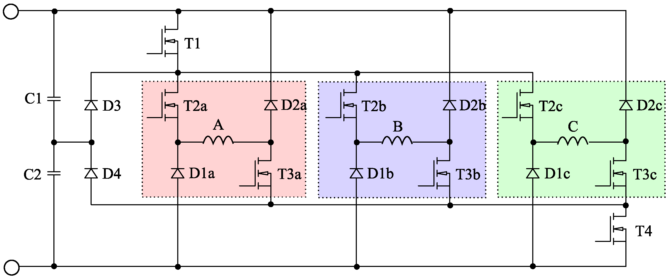
2. Switch-Sharing and Introducing RANPC Topology
Sizing of Power Capacitor for RANPC
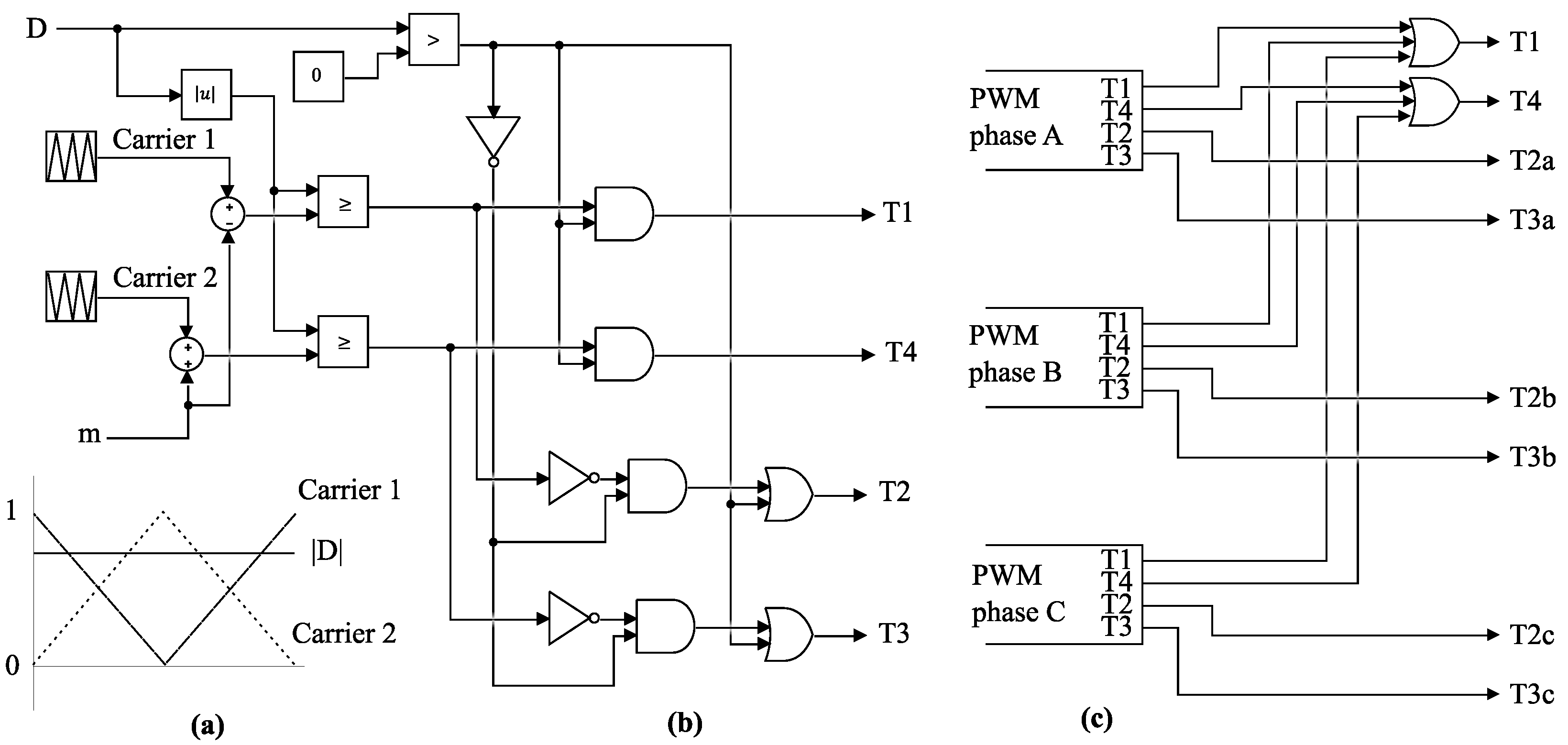
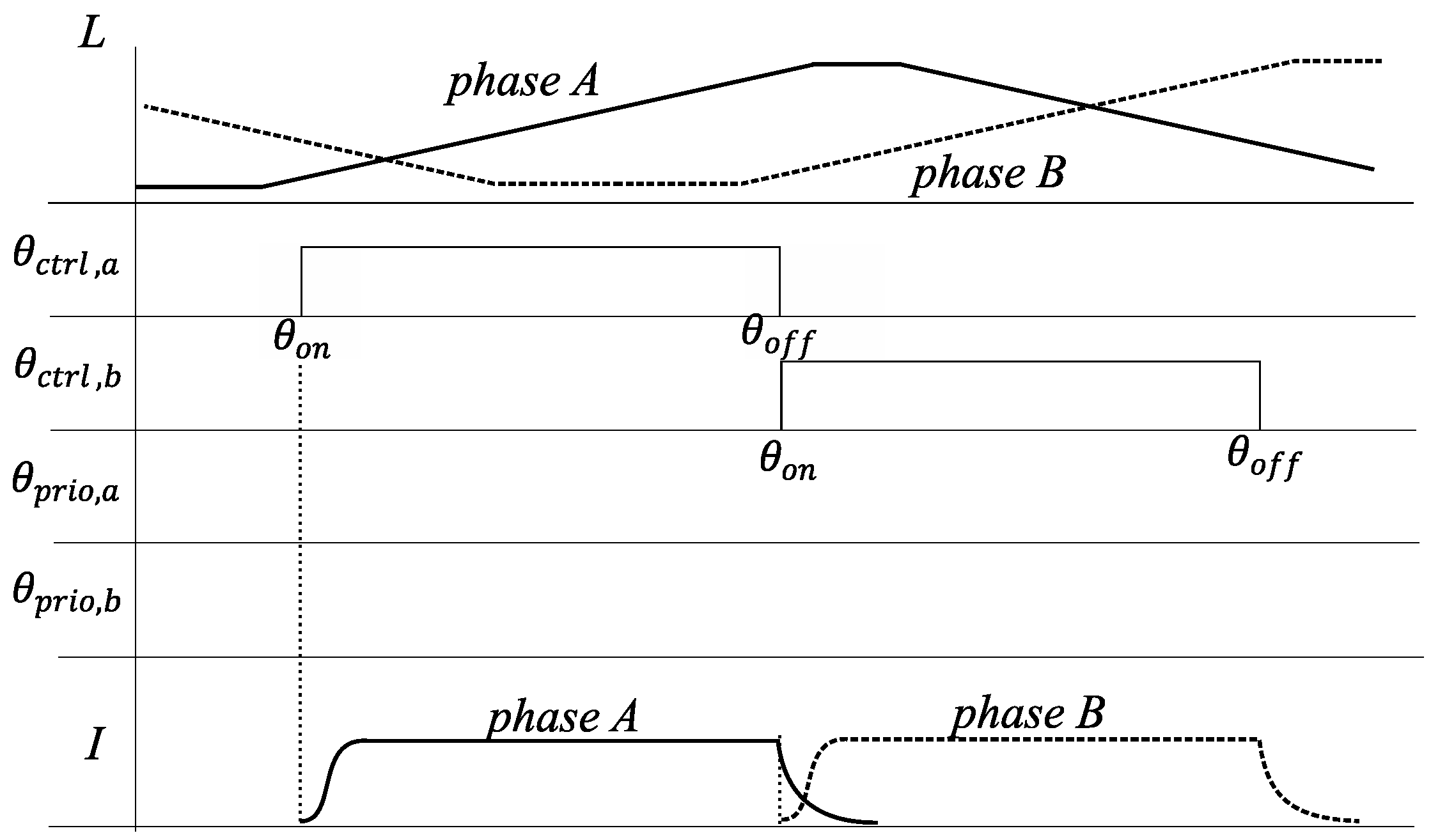
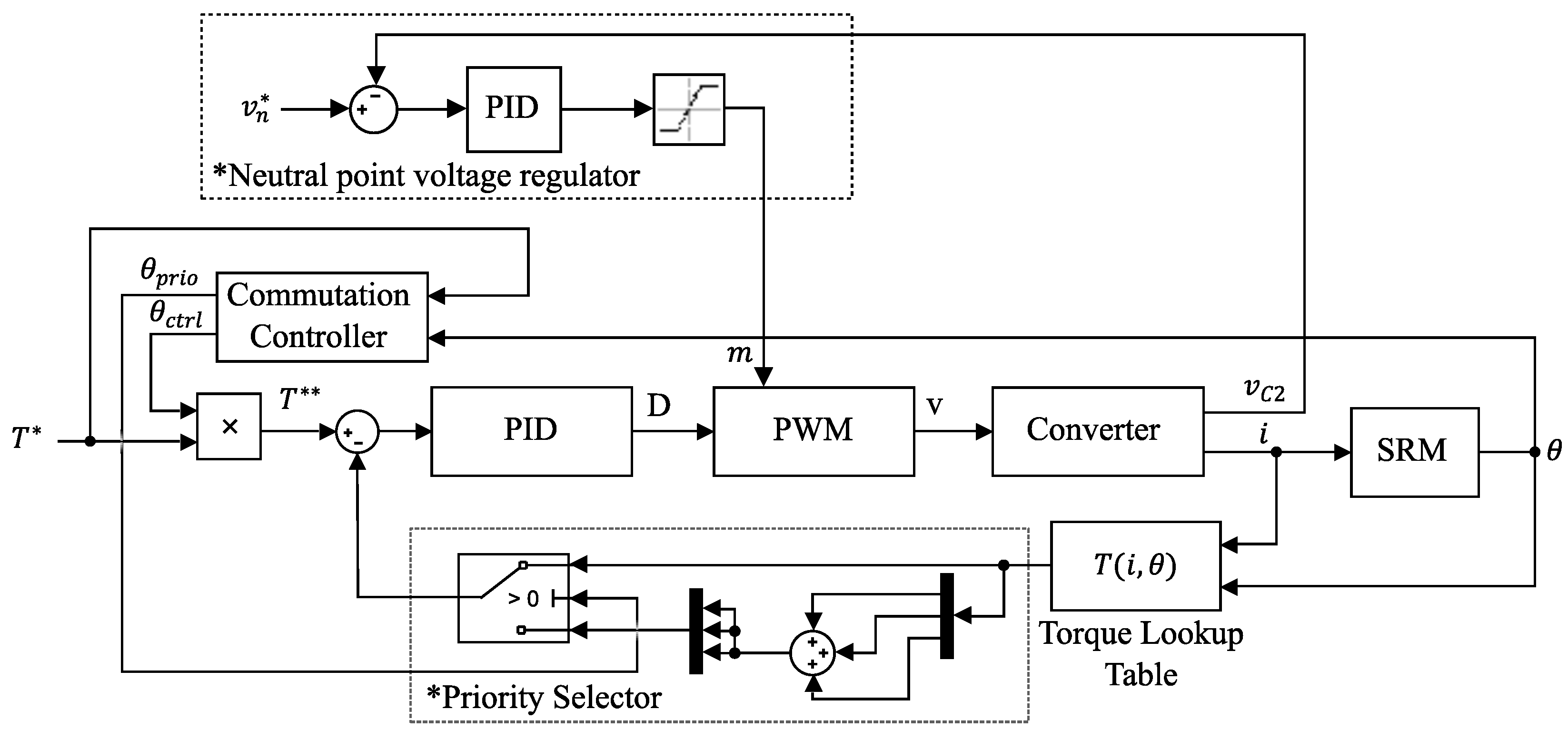
3. Control
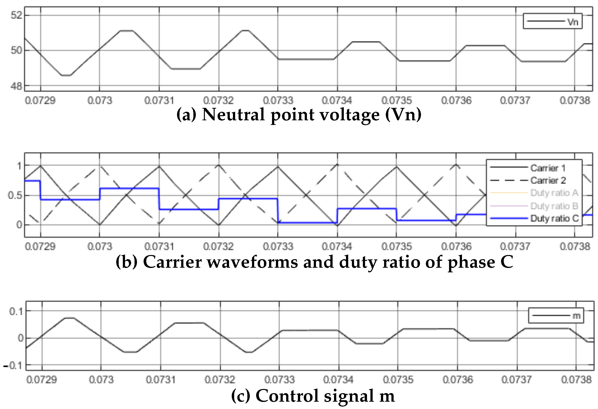
Regulation of Neutral Point Voltage
4. Materials and Methods
5. Simulation Results
6. Discussion
7. Conclusions
Author Contributions
Funding
Data Availability Statement
Conflicts of Interest
Abbreviations
| SRM | Switched Reluctance Machine |
| ANPC | Asymmetric Neutral Point Clamped |
| AFC | Asymmetric Flying Capacitor |
| ACCHB | Asymmetric Cascaded Cell Half Bridge |
| AMM | Asymmetric Modular Multilevel |
| PWM | Pulse Width Modulation |
| RANPC | Reduced Asymmetric Neutral Point Clamped |
References
- Liang, J.; Lee, D.H.; Xu, G.; Ahn, J.W. Analysis of Passive Boost Power Converter for Three-Phase SR Drive. IEEE Trans. Ind. Electron. 2010, 57, 2961–2971. [Google Scholar] [CrossRef]
- Gan, C.; Wu, J.; Hu, Y.; Yang, S.; Cao, W.; Guerrero, J.M. New Integrated Multilevel Converter for Switched Reluctance Motor Drives in Plug-in Hybrid Electric Vehicles with Flexible Energy Conversion. IEEE Trans. Power Electron. 2017, 32, 3754–3766. [Google Scholar] [CrossRef] [Green Version]
- Yi, F.; Cai, W. A Quasi-Z-Source Integrated Multiport Power Converter as Switched Reluctance Motor Drives for Capacitance Reduction and Wide-Speed-Range Operation. IEEE Trans. Power Electron. 2016, 31, 7661–7676. [Google Scholar] [CrossRef]
- Gan, C.; Sun, Q.; Wu, J.; Kong, W.; Shi, C.; Hu, Y. MMC-Based SRM Drives with Decentralized Battery Energy Storage System for Hybrid Electric Vehicles. IEEE Trans. Power Electron. 2019, 34, 2608–2621. [Google Scholar] [CrossRef]
- Anand, A.; Singh, B. Modified Dual Output Cuk Converter-Fed Switched Reluctance Motor Drive with Power Factor Correction. IEEE Trans. Power Electron. 2019, 34, 624–635. [Google Scholar] [CrossRef]
- Peng, F.; Ye, J.; Emadi, A. An Asymmetric Three-Level Neutral Point Diode Clamped Converter for Switched Reluctance Motor Drives. IEEE Trans. Power Electron. 2017, 32, 8618–8631. [Google Scholar] [CrossRef]
- Watkins, S.J.; Corda, I.; Zhang, L. Multilevel asymmetric power converters for switched reluctance machines. In Proceedings of the 2002 International Conference on Power Electronics, Machines and Drives, Sante Fe, NM, USA, 4–7 June 2002; pp. 195–200. [Google Scholar] [CrossRef]
- Patil, D.; Wang, S.; Gu, L. Multilevel Converter Topologies for High-Power High-Speed Switched Reluctance Motor: Performance Comparison. In Proceedings of the 2016 IEEE Applied Power Electronics Conference and Exposition (APEC), Long Beach, CA, USA, 20–24 March 2016; pp. 2889–2896. [Google Scholar] [CrossRef]
- Yamada, N.; Hoshi, N. Experimental Verification on A Switched Reluctance Motor Driven by Asymmetric Flying Capacitor Multilevel H-bridge Inverter. In Proceedings of the 6th International Conference on Renewable Energy Research and Applications, San Diego, CA, USA, 5–8 November 2017; Volume 5, pp. 3–8. [Google Scholar]
- Lee, D.H.; Ahn, J.W. A Novel Four-Level Converter and Instantaneous Switching Angle Detector for High Speed SRM Drive. IEEE Trans. Power Electron. 2007, 22, 2034–2041. [Google Scholar] [CrossRef]
- Lee, D.H.; Wang, H.; Ahn, J.W. An Advanced Multi-Level Converter for Four-Phase SRM Drive. In Proceedings of the 2008 IEEE Power Electronics Specialists Conference, Rhodes, Greece, 15–19 June 2008; pp. 2050–2056. [Google Scholar] [CrossRef]
- Song, S.; Peng, C.; Guo, Z.; Ma, R.; Liu, W. Direct Instantaneous Torque Control of Switched Reluctance Machine Based on Modular Multi-Level Power Converter. In Proceedings of the 2019 22nd International Conference on Electrical Machines and Systems (ICEMS), Harbin, China, 11–14 August 2019; Volume 1, pp. 1–6. [Google Scholar] [CrossRef]
- Malekpour, A.R.; Torkaman, H.; Toulabi, M.S. A Quasi-Three-level Asymmetric NPC Converter with less Switches for Switched Reluctance Motor Drives Cost Reduction. In Proceedings of the 34th International Power System Conference, PSC 2019, Tehran, Iran, 9–11 December 2019; pp. 188–194. [Google Scholar] [CrossRef]
- Scholtz, P.A.; Gitau, M.N. Carrier Modulation Schemes of Asymmetric, Multileveled, Switched Reluctance Machine Drives. In Proceedings of the 2021 22nd IEEE International Conference on Industrial Technology (ICIT), Valencia, Spain, 10–12 March 2021; pp. 160–165. [Google Scholar] [CrossRef]
- Abdel-Aziz, A.A.; Ahmed, K.H.; Wang, S.; Massoud, A.M.; Williams, B.W. A Neutral-Point Diode-Clamped Converter with Inherent Voltage-Boosting for a Four-Phase SRM Drive. IEEE Trans. Ind. Electron. 2020, 67, 5313–5324. [Google Scholar] [CrossRef]
- Liang, J.; Lee, D.H.; Ahn, J.W. Direct instantaneous torque control of switched reluctance machines using 4-level converters. IET Electr. Power Appl. 2009, 3, 313. [Google Scholar] [CrossRef]
- Fuengwarodsakul, N.; Menne, M.; Inderka, R.; De Doncker, R. High-Dynamic Four-Quadrant Switched Reluctance Drive Based on DITC. IEEE Trans. Ind. Appl. 2005, 41, 1232–1242. [Google Scholar] [CrossRef]
- Brauer, H.J.; Hennen, M.D.; Doncker, R.W.D. Control for Polyphase Switched Reluctance Machines to Minimize Torque Ripple and Decrease Ohmic Machine Losses. IEEE Trans. Power Electron. 2012, 27, 370–378. [Google Scholar] [CrossRef]
- Xue, X.D.; Cheng, K.W.; Ho, S.L. Optimization and evaluation of torque-sharing functions for torque ripple minimization in switched reluctance motor drives. IEEE Trans. Power Electron. 2009, 24, 2076–2090. [Google Scholar] [CrossRef] [Green Version]
- Radun, A. Analytically computing the flux linked by a switched reluctance motor phase when the stator and rotor poles overlap. IEEE Trans. Magn. 2000, 36, 1996–2003. [Google Scholar] [CrossRef]
- Miller, T.; McGilp, M. Nonlinear theory of the switched reluctance motor for rapid computer-aided design. IEE Proc. B Electr. Power Appl. 1990, 137, 337. [Google Scholar] [CrossRef]
- Ilic’-Spong, M.; Marino, R.; Peresada, S.M.; Taylor, D.G. Feedback Linearizing Control of Switched Reluctance Motors. IEEE Trans. Autom. Control 1987, 32, 371–379. [Google Scholar] [CrossRef]


| State | T1 | T2 | T3 | T4 | Applied Voltage | Conduction Loss | Energy Transfer * | Condition |
|---|---|---|---|---|---|---|---|---|
| 1 | 1 | 1 | 1 | 1 | ||||
| 2 | 1 | 1 | 1 | 0 | C2 ↑ C1 ↓ | |||
| 3 | 0 | 1 | 1 | 1 | C1 ↑ C2 ↓ | |||
| 4 | 1 | 1 | 0 | 0 | 0 | |||
| 5 | 0 | 1 | 1 | 0 | 0 | |||
| 6 | 0 | 0 | 1 | 1 | 0 | |||
| 7 | 0 | 1 | 0 | 0 | C2 ↓ C1 ↑ | |||
| 8 | 0 | 0 | 1 | 0 | C1 ↓ C2 ↑ | |||
| 9 | 0 | 0 | 0 | 0 |
| N + 1 | State 5, 7, 8, 9 | State 2, 4 | State 3, 6 | State 1 |
|---|---|---|---|---|
| N | ||||
| State 1 | ||||
| State 2 | ||||
| State 3 | ||||
| State 4 | 0 | 0 | 0 | 0 |
| State 5 | 0 | |||
| State 6 | 0 | 0 | 0 | 0 |
| State 7 | 0 | 0 | ||
| State 8 | 0 | 0 | ||
| State 9 |
| Model | H55PWBKM-1850 | |
|---|---|---|
| Specification | Value | Description |
| 2.5 Ohm | Phase resistance | |
| 52 mH | Aligned inductance | |
| 9 mH | Unaligned inductance | |
| 2.5 A | Rated current | |
| 120 V | Rated voltage | |
| q | 3 | Phases |
| 12/8 | Pole configuration | |
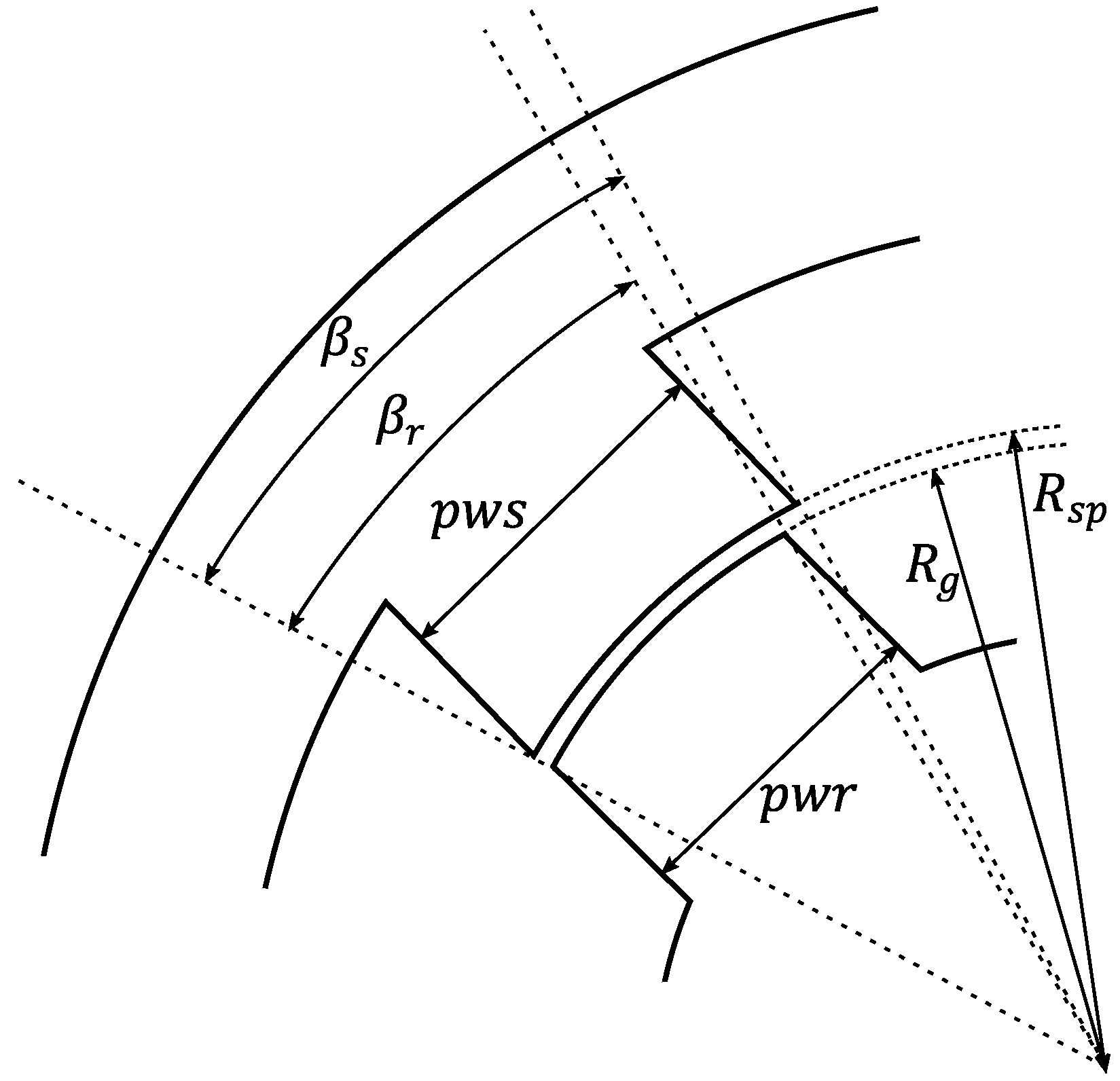
| 41.45 mm | Outer radii of the rotor | |
| 41.75 mm | Inner radii of stator poles | |
| 11.7 mm | Stator pole width | |
| 10.8 mm | Rotor pole width | |
| 14.971 | Rotor pole angle | |
| 16.110 | Stator pole angle | |
| K | 0.165 H/rad | Derivative of inductance relative to angular position |
Publisher’s Note: MDPI stays neutral with regard to jurisdictional claims in published maps and institutional affiliations. |
© 2022 by the authors. Licensee MDPI, Basel, Switzerland. This article is an open access article distributed under the terms and conditions of the Creative Commons Attribution (CC BY) license (https://creativecommons.org/licenses/by/4.0/).
Share and Cite
Scholtz, P.A.; Gitau, M.N. Asymmetric Neutral Point Diode Clamped Topology with Reduced Component Count for Switched Reluctance Machine Drive. Energies 2022, 15, 2468. https://doi.org/10.3390/en15072468
Scholtz PA, Gitau MN. Asymmetric Neutral Point Diode Clamped Topology with Reduced Component Count for Switched Reluctance Machine Drive. Energies. 2022; 15(7):2468. https://doi.org/10.3390/en15072468
Chicago/Turabian StyleScholtz, Pieter Antonie, and Michael Njoroge Gitau. 2022. "Asymmetric Neutral Point Diode Clamped Topology with Reduced Component Count for Switched Reluctance Machine Drive" Energies 15, no. 7: 2468. https://doi.org/10.3390/en15072468
APA StyleScholtz, P. A., & Gitau, M. N. (2022). Asymmetric Neutral Point Diode Clamped Topology with Reduced Component Count for Switched Reluctance Machine Drive. Energies, 15(7), 2468. https://doi.org/10.3390/en15072468