Abstract
In this paper, a design methodology for synchronous reluctance machines (SynRM) working with variable torque and speed profiles was presented. Unlike conventional solutions which size the machine considering a reduced number of working points in order to reduce the computation time, the solution proposed in this paper takes into account all the points which allow for better management of the constraints along the cycle to avoid an oversizing of the machine. To solve this problem with a reduced computation time, the geometry of the motor as well as the control strategy were optimized in two steps. In the first step, the d-q axis stator currents were analytically expressed. In the second step, the geometry was optimized with the use of a genetic algorithm. As an application of this method, the case of a small and low-cost electric vehicle (EV) was chosen with the objective of minimizing both the mass and the energy lost for the standardized urban dynamometer driving schedule (UDDS). The method was based on the use of a 1-D analytical model which was validated by a 2D finite element analysis (FEA).
1. Introduction
In recent years, a lot of research has been done on motor designs for electric vehicle applications [1,2,3]. One of the main issues related to this subject is taking into account the standard driving cycle, which is usually composed of several hundred working points in the optimization process. The optimization of an electrical machine considering a working cycle must consider the optimization of the time-dependent variables (currents or voltages). In addition to the geometric parameters, the control strategy must be optimized for each working point. Then, the use of a genetic algorithm, for example, coupled with an analytical model leads quickly to a huge computation time, which is not suitable in a sizing step. The computation time can be estimated by the following formula: , where and are, respectively, the number of generations and individuals to optimize the geometric parameters, and are, respectively, the number of generations and individuals to optimize the current at each working cycle, is the number of working point and is the time needed to evaluate the function. For example, with a cycle defined by 1000 points, the computation time can be longer than two years with 200 generations, 200 individuals and a typical duration of 50 µs per evaluation. Then, the whole cycle is commonly reduced to the most significant points generally chosen according on an energy criterion [4,5,6,7,8,9,10,11]. In this case, each point represents an energy center of gravity selected in the torque-speed plane. The result can be improved by combining a finite element analysis with analytical models [12,13] but it remains an approximate and partial solution because the optimal choice of the control strategy during the cycle and the thermal behavior with the transient regime are not properly taken into account, in, for example, the maximum torque per ampere (MTPA) control strategy or another control strategy, whatever the working point [14,15]. The MPTA control strategy minimizes copper losses for a given torque. However, iron losses can be significant, especially in high-speed machines, and it may be interesting to consider from the design step, a control mode that minimizes both copper and iron losses in order to maximize the energy efficiency [16,17,18]. On the other hand, for a machine working at variable torque and speed, it is important to control the maximum temperature and the moment of its apparition. A calculation based on continuous losses leads to undersizing of the machine, whereas a calculation based on peak losses leads to oversizing.
In this paper, a design methodology which allows, at the same time, to consider the whole cycle operating points and an optimal control strategy was presented. This study is an enhancement of a research work presented in [19,20,21] that was carried out for the surface permanent magnet synchronous machine. To our knowledge, such an approach has been never made for SynRM. With the need to reduce CO2 emissions and pollution in urban centers, the demand for small electric vehicles is expected to increase significantly in the coming years. In this market, where volumes will be important, the cost criterion and the environmental impact will be preponderant. In this context, the SynRM presents interesting advantages compared to the permanent magnet machines (PMSM). The design of a rotor without magnets is interesting to reduce, significantly, both the cost and the risk supply disruption in a very tight market [22,23]. There is also no risk of magnet demagnetization. In this case, compared to PMSM, the loss of power density (acceptable for a small power application) is widely compensated by a reduced cost (by almost a factor of two), increased efficiency, and reliability [24].
In this paper, the design methodology was based on equivalent circuit models in the d-q axis, allowing for the generalization of its use in other type of machines. The key point of the proposed method is that the optimization process of the time-varying optimization parameters (,) is done analytically in an initial step. The numerical optimization tool is used only in a second step to find the geometric parameters of the motor. As these parameters are not time-dependent, the computation time is then significantly reduced, as if it were done for only one operating point.
The paper is organized as follows. In Section 2, the analytical model of the SynRM is given. The inductances and resistances of the d-q axis equivalent circuits as well as saturation, mechanical and thermal constraints are detailed. In Section 3, the design optimization method is presented. Section 4 presents the application where the motor is sized considering the urban dynamometer driving schedule (UDDS). Finally, the key parameters such as, torque, surfacic permeances, and iron losses of the selected optimal motor were validated by comparison with a finite element analysis (FEA).
2. Analytical Model
In this section, a 1-D analytical modeling of the SynRM is proposed with the aim of optimizing. The design and the geometric parameters are shown in Figure 1. The stator is assumed to have radial teeth and slots with coils connected to produce a three-phase winding. Each phase is made of one full pitch coil and turns/phase/pole. Such a winding, easier to assemble, thus reduces the manufacturing cost. The salient pole rotor is assumed to be skewed continuously by one stator slot pitch to improve the quality of the energy conversion and reduce the torque ripple. In the following, the steel parts are assumed to be infinitely permeable and rotor losses neglected.
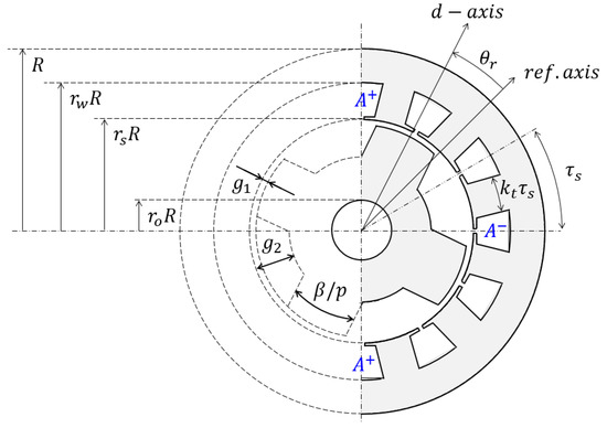
Figure 1.
Design of the SynRM and main geometric parameters (with ).
2.1. d-q Axis Equivalent Circuit Models
Figure 2 represents the d-q axis equivalent circuits, including the equivalent iron loss resistance of the motor [25,26]. , and , are, respectively, the stator currents and terminal voltages in the rotor reference frame. Assuming that the terms and can be neglected for a design optimization, the d-q axis voltage and are therefore given as:

Figure 2.
d-q axis equivalents circuits.
Using the Concordia’s transformation, the electromagnetic power is:
The coppers losses and iron losses are:
Since (1) and (2), these losses can be also written as a function of currents and only:
2.2. Flux Densities
The fundamental component of the airgap flux density created by the stator can be calculated since the surfacic permeance . Ref. [27] such as:
The surfacic permeance limited to its average value and first harmonic component (see Figure 3) is written:
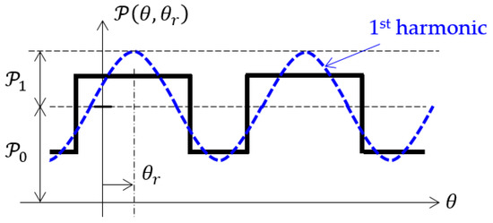
Figure 3.
Permeance function.
The first harmonic of the total stator magnetomotive force (MMF) is given by:
where, is the winding factor due to the skewing effect. From the half skew mechanical angle , it is given by:
Then, it can be demonstrated that he magnitude of the airgap flux density is:
With:
And:
Thanks to the Gauss’s law, it is possible to express the magnitude of the flux densities in the steel part, the stator tooth (), the stator yoke () and the rotor pole (). It gives:
2.3. Resistances and Inductances Models
The copper conductivity is considered constant and magnetic saturation is partially taken into account by correcting the harmonic components of surfacic permeances and which will be detailed further.
2.3.1. Resistances
The calculation of the copper resistance is calculated from:
with the slot fill factor:
and the cross-section area of one stator slot:
it gives:
The resistance represents the magnetic losses in the yoke and tooth of the stator. From (5), this resistance can be expressed as:
with:
the magnitude of the voltage associated with the magnitude of the airgap flux density obtained from the Faraday’s law. Iron losses can be written [21]:
with:
Since (15), (16), and (22)–(24) it gives:
2.3.2. d-q Axis Inductances
The d-q inductances can be calculated by means of the airgap surfacic permeance (or permeance function) as [28]:
where is the mean value and is the amplitude of the first harmonic component. On a first approach, the permeance function can be simply represented as shown in the Figure 3. Considering the stator slotting effect, by the use of Carter’s coefficient , it can be approximated by the black rectangular function with:
Therefore, the mean value and are given by:
The calculation of by the Equation (27) may lead to a significant error due to diverse effects, such as non-radial flux lines, non-sinusoidal winding distribution, flux leakage, etc. These effects are usually corrected by a coefficient kLd [29]. For the considered geometry, this coefficient has been evaluated with a 2D finite element analysis.
2.4. Constraints
2.4.1. Thermal Constraint
The thermal model used in this paper is the well-known lumped-parameter thermal model (LPTN) [30]. To reduce the computation time, the slot is replaced by a homogeneous block with an equivalent conductivity and equivalent specific heat capacity. In the axial direction, thermal resistances are neglected inside the machine, however, convection is considered.
For each evaluated machine, the temperature elevation in the winding θc(t) is calculated from the equivalent circuit represented in Figure 4c which represents half a slot pitch.
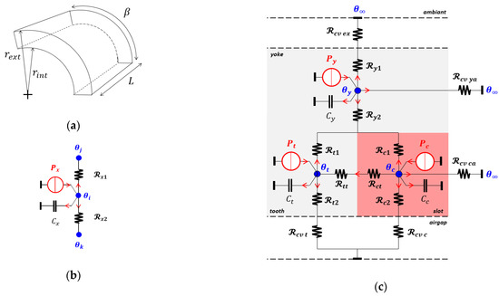
Figure 4.
Cylindrical piece (a); with its thermal model (b); and thermal model of the whole machine (c).
In the radial direction, each cylindrical element is modeled by an equivalent circuit, as shown in Figure 4a,b with:
where the subscript is for the yoke, for the teeth and for the slot. Between the tooth and the slot, the thermal resistances and are calculated considering parallelepiped shapes:
With , the length of the element. The convection heat transfer coefficients, for the calculation of and , depend on several parameters (geometry, air velocity, etc.,). We assume here the same coefficient for all surfaces, considering the following empirical formula [31,32]:
where is the speed of the air and the coefficient for a natural convection. With and by the use of a fan, it gives The convective thermal resistances are then given by:
where is the surface exposed to the forced air flow (where is for the external surface at radius , for the internal surface at radius , and respectively for the surfaces at the end-space).
At each node of the LPTN (Figure 4c) the following equation can be written:
Which leads to a system of first order differential equations commonly presented in the matrix form:
is the thermal conductivity matrix, the thermal capacity vector, the matrix of losses and the temperature vector such as The main constant parameters used are given in Table 1.

Table 1.
Constant parameters for thermal analysis.
2.4.2. Mechanical Constraint
The geometry of the rotor is constrained by two main factors: the maximum stress and the first natural frequency. The maximum stress is proportional to the square of the peripheral speed. Therefore, the peripheral speed of the rotor cannot exceed the limit accepted by the material. Then:
where and are the maximum peripheral speed and the maximum angular speed respectively. In order to avoid the vibrations, the maximum speed is kept lower than the first critical speed [33]:
where is the mass of the rotor and is the bearing stiffness.
Generally, the maximum circumferential speed constraint is more significant than the first critical speed one [34]. In this paper, only (39) is taken into account. For the SynRM with laminated rotor, can be achieved over 200 m/s [35].
2.4.3. Saturation Constraint
The magnitude of the flux density is limited to , since Equations (12) and (15)–(17), in each magnetic part of the machine, stator yoke, stator teeth, rotor yoke and rotor teeth.
3. Design Optimization
In this part, the sizing methodology is presented. Because mass and material costs are strongly correlated here, we have chosen the following two objectives: minimization of the mass and minimization of the energy lost per cycle. Because the control strategy must be considered, we propose here to present the case of a control strategy that minimizes electrical losses at each working point. However, other strategies can be considered, such as the maximum torque per ampere control obtained with .
The optimization process is achieved by a two-step procedure consisting of optimizing firstly the control variables (, ) and secondly the geometric ones (, , , , , , , ). In the first step, the current variables are optimized to minimize the losses at any working point of the cycle. Thus, the optimal currents obtained are analytic functions of the geometrical parameters. These ones are optimized, in the second step, in order to minimize both the average losses during the cycle and the mass of the motor. Figure 5 represents the general flowchart of the optimization process.
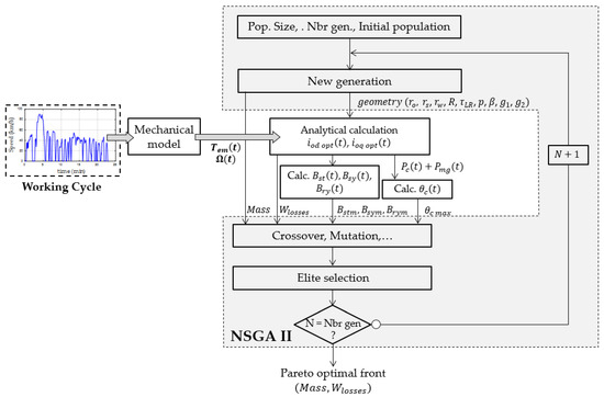
Figure 5.
General flowchart of the optimization process.
3.1. D-q Axis Current Expressions
In the case considered, the expressions of the currents that minimize losses have to be found. From (3), can be written:
Substituting into (6) and (7), the sum of copper and iron losses, at a given working point, is expressed as a function of as follows:
where:
Equation (42) has a form with and , which are constant and positive. It can be easily demonstrated that is minimal and equal to when or . Thus, the optimal value of , noted , which minimize the total losses can be expressed as below:
3.2. First Objective Function
By substituting (45) into (42), the energy lost during the cycle can be evaluated uniquely from the d-q axis inductances and and the resistances and , torque and speed of the working point as follows:
3.3. Second Objective Function
Only the masses of the active parts are considered here. and are respectively the mass of the iron and the mass of the slots (copper + insulating). They are calculated since the volume and specific densities and as below:
3.4. Design Optimization
In (46), the d-q axis inductances , and the resistances , are replaced by their expressions (21), (26)–(28) respectively, so that the first objective function depends on the time-independent optimization parameters (, , , , , , , ). The torque and speed profiles are the inputs of the problem. To minimize the two objective functions, the NSGA II [36] optimization algorithm is used here (see Figure 5). The NSGA II is today commonly used, and preferred to gradient-based algorithms, in the design optimization of electrical machines because of its simplicity, its capability to find global optimum in a multi-objective problem and a better convergence [37].
4. Application
In this part, the design method presented previously is applied to the design optimization of a motor for a small urban electrical car. The speed and power profiles are calculated from the specifications of the car and driving cycle. The chosen driving cycle is the UDDS one. The standard UDDS cycle is made of 1380 points with one point per second. To reduce the computation time and keep the correct dynamic behavior of the system, we have reduced the cycle with one point every 5 s.
4.1. Car Specifications and Mechanical Model
We consider an urban car whose specifications are summarized in Table 2. From these data and the speed profile (UDDS driving cycle) represented in Figure 6, the required torque on the wheel can be found by means of the classical mechanical formula below (assuming no incline):

Table 2.
Vehicle data.
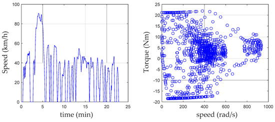
Figure 6.
Speed and torque to the wheel profiles.
Based on these data, the main characteristics of the machine are presented in Table 2.
4.2. Optimization Results
The constants used are given in the Table 3. The minimization of the Formulas (46) and (47) is done by the numerical optimization algorithm NSGA-II, leading to a Pareto optimal front. The number of generations and the population size are, respectively, chosen from 800 to 400. The result is obtained with an acceptable computation time of 2 h considering a working cycle of approximately 4 h with 2770 points.

Table 3.
Constant data.
To start, two cases are presented. In the first case, the working cycle is made of a continuous series of 5 UDDS whose characteristics are given in Table 4. In this case, the steady state thermal regime is reached. In the second case, the working cycle is made of 2 UDDS only with a long stop in between leading to an intermittent thermal regime. The Pareto fronts of optimal machines are shown in Figure 7. Here, the consumption per cycle is plotted (instead of ) with the maximum temperature in the winding added for some points along the front. For both cases considered and the lightest machines, the maximum temperature is reached as illustrated in Figure 8. It should be noted that the mass of the lightest machine is 23 kg for a sizing with the continuous duty while it is 19.6 kg for the intermittent one. Thus, considering an intermittent operation allows to reduce by 18% the mass of the machine. Conversely, consumption is higher by 10.5%. This result illustrates the interest of the proposed method and its possibilities.

Table 4.
Specific data of motor torque-speed profiles with a gear box ratio G = 10.
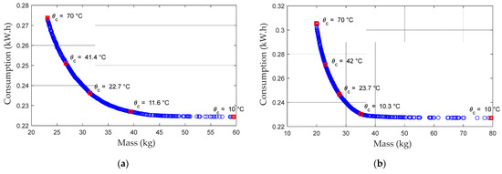
Figure 7.
Pareto optimal front with temperature elevation in continuous (a) and intermittent (b) duties.
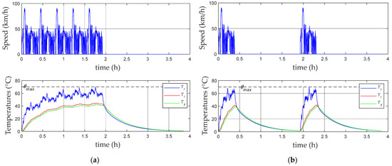
Figure 8.
Working cycles and temperatures in continuous (a); and intermittent (b) duties.
4.3. Optimal Solution Selected: Analysis and Validation
To validate the model used and the proposed design methodology, we propose to select the lightest machine with a steady state thermal regime as the optimal machine. Table 5 shows the geometrical parameters and the main performances of the optimal motor. The mass of the optimal motor is 23.1 kg, which represents 4.6% of the vehicle mass. During operation (), the average efficiency of the SynRM is 95% (excluding mechanical losses). The motor current can be deduced with a given number of turns per phase per pole . The number of turns is chosen considering a maximum voltage of the power electronic converter at 48 V. Such a parameter could be optimized with the power electronic converter in the design process and will be discussed in a further work. Figure 9 represents the locus of optimal d-q axis stator currents and voltages during one cycle. It shows clearly that, whatever the working point, the control strategy that minimizes electrical losses leads to a control at a constant ratio and a current angle . The optimum control strategy found here is practically the MPTA () control. This result is due to the fact that iron losses remain low compared to copper losses. The stator flux densities during one cycle, with the respect the saturation limit in the teeth and in the yoke, are shown in Figure 10.

Table 5.
Optimal geometry data and optimal performances of the motor.
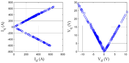
Figure 9.
Locus of optimal d-q axis stator currents and voltages during one cycle.
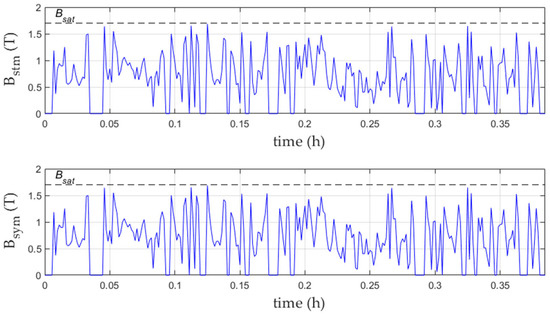
Figure 10.
Maximum flux densities versus time in the stator yoke and stator teeth.
The performances of the optimal motor given in Table 5 has been validated by a 2D element finite analysis (with the free software program FEMM 4.2). Table 6 summarizes these results. A magneto-static simulation has been used which the current density is imposed. On the outer stator radius, the Dirichlet’s boundary is applied (). The FEA assumes the actual BH curve for steel grade M270-35A (see Figure 11).

Table 6.
Analytical and 2D FEM results.
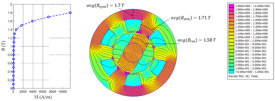
Figure 11.
M270-35 A Flux lines and flux density distribution at full load.
Figure 11 shows the flux density with the flux lines at the maximum electromagnetic torque. It can be seen that the flux densities in the magnetic parts remain in acceptable limits with respect to the saturation limit considered in the analytical calculation. In Figure 12, the evolution, with the position of the rotor, of the average values of the maximum flux density along the considered cross section (black dotted lines) are plotted in the stator yoke and rotor tooth. At the maximum torque the variation between the mean value (red dotted lines in Figure 12) obtained by the FEA and the analytical calculation is 1.4 % for , 0.8% for and −7.8% for Figure 13 presents the results relating to and Ratios between airgap surfacic permeance values obtained by the analytical model and by the FEM are plotted for different positions of the rotor at the maximum electromagnetic torque.
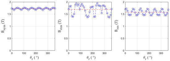
Figure 12.
Maximum flux densities at with the position: in the stator yoke (), stator teeth () and rotor tooth ().
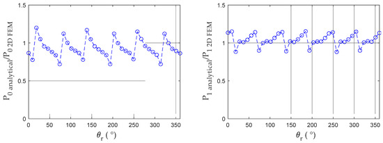
Figure 13.
Comparission between analytical and FEM airgap permeances and .
4.4. Comparison of the Proposed Method and Classical One
In order to compare the result obtained with the proposed method and the optimization obtained by the use of the classical technique we have considered the drive cycle reduced to eight points and optimized the machine since these eight points. Each point is weighted by its density of probability (ratio between its energy weight and the total energy consumed on the cycle). The result obtained is a machine that is 7% heavier (24.9 kg) for a heating calculated on the basis of the eight weighted losses. However, the thermal simulation of this machine over the cycle shows that the maximum temperature is not reached (see Figure 14b), which shows that the optimization over the reduced cycle leads here to an oversizing of the machine.
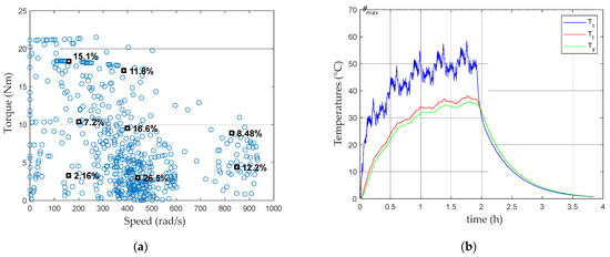
Figure 14.
Equivalent torque-speed (a); and thermal behavior of optimized machine considering the reduced cycle (b).
5. Conclusions
In this paper, a pre-design optimization method that considered both torque and speed profiles, applied to the case of the SynRM, was presented. While the classical methods presented in the bibliography used an energetic approach to take into account the driving cycle, the method presented here, by its temporal approach, keeps all the operating points which obtains a more efficient sizing by a better management of the constraints, such as the thermal constraints and the control strategy. An application of the proposed method to size a motor for an urban car and the driving cycle UDDS was then carried out. The analysis of the optimal motor selected shows a good agreement between the analytical model used in the optimization process and the 2D FEA. It should be noted that even if the magnetic model is quite simple, the results obtained in this first approach are quite good for a pre-dimensioning. In future work, a more efficient model integrating both the saturation of the magnetic material and the power electronic converter will be presented. Thus, in the next paper, the consideration of magnetic saturation by the use of a reluctance network model will be presented. For the power electronics converter, in addition to the constraints on the sizing of the machine, losses in the power components will be integrated in the objective function in order to maximize the energy efficiency of the whole power chain conversion.
Author Contributions
Conceptualization, N.B. and L.D.; methodology, N.B. and L.D.; software, N.B. and L.D.; validation, N.B., L.D. and L.M.; formal analysis, N.B. and L.D.; investigation, N.B. and L.D.; resources, N.B. and S.B.; data curation, N.B. and L.D.; writing—original draft preparation, N.B. and L.D.; writing—review and editing, N.B.; visualization, N.B.; supervision, N.B.; project ad-ministration, N.B. and S.B. All authors have read and agreed to the published version of the manuscript.
Funding
This research received no external funding.
Data Availability Statement
Not applicable.
Conflicts of Interest
The authors declare no conflict of interest.
Abbreviations
| magnitude of the resulting airgap flux density [T] | |
| Flux density at saturation [T] | |
| magnitude of the airgap flux density [T] | |
| magnitude of the flux density in the stator teeth [T] | |
| magnitude of the flux density in the stator yoke [T] | |
| equivalent heat capacity of material [J/kg.°C] | |
| air drag coefficient | |
| stator magnetomotive force [A] | |
| rolling resistance coefficient | |
| gear box ratio | |
| minimum airgap thickness [m] | |
| maximum airgap thickness [m] | |
| heat transfer coefficient [W/m2.K] | |
| d- and q- axis currents [A] | |
| rms stator current [A] | |
| current density [A/m2] | |
| additional magnetic loss coefficient | |
| Carter’s coefficient | |
| eddy currents specific loss coefficient | |
| slot fill factor | |
| hysteresis specific loss coefficient | |
| coefficient for correcting active length due to end winding | |
| coefficient for correcting the inductance with saturation | |
| bearing stiffness [N/m] | |
| tooth opening to the slot pitch ratio in the stator | |
| winding factor | |
| active length [m] | |
| axis inductance [H] | |
| axis inductance [H] | |
| mass of the vehicle [kg] | |
| slot mass (copper + insulating) [kg] | |
| iron mass [kg] | |
| number of conductors/phase/pole for the stator | |
| number of pole pairs | |
| copper losses [W] | |
| Total electrical losses [W] | |
| electromagnetic power [W] | |
| iron losses [W] | |
| surfacic permeance [H/m2] | |
| maximum value of the surfacic permeance [H/m2] | |
| minimum value of the surfacic permeance [H/m2] | |
| average value of the surfacic perméance [H/m2] | |
| magnitude of the first harmonic of the surfacic perméance [H/m2] | |
| external radius [m] | |
| winding resistance [] | |
| reduced inner stator winding radius [m] | |
| reduced stator winding radius [m] | |
| reduced internal rotor radius [m] | |
| iron loss resistance [] | |
| conduction thermal resistance [W/K] | |
| convective thermal resistance [W/K] | |
| frontal area of the vehicle [m2] | |
| external surface [m2] | |
| section of conductors [m2] | |
| section of one slot [m2] | |
| time [s] | |
| electromagnetic torque [Nm] | |
| d- and q- axis terminal voltage [V] | |
| volume of the stator teeth [m3] | |
| volume of the stator yoke [m3] | |
| peripheral speed of the rotor [m/s] | |
| speed of the vehicle [m/s] | |
| stator tooth width [m] | |
| stator yoke thickness [m] | |
| energy lost per working cycle [J] | |
| number of slots | |
| electrical rotor pole arc [rad] | |
| skew mechanical angle (rad) | |
| Angle with the reference axis [rad] | |
| temperature elevation in the winding [K] | |
| position of the rotor (rad) | |
| thermal conductivity [W/m.K] | |
| current angle [rad] | |
| iron density [kg/m3] | |
| Slot material density [kg/m3] | |
| electrical conductivity [S] | |
| active length to outer stator ration () | |
| stator slot pitch | |
| mechanical angular velocity [rad/s] | |
| Angular frequency [rad/s] |
References
- Zwyssig, C.; Round, S.D.; Kolar, J.W. An Ultrahigh-Speed, Low Power Electrical Drive System. IEEE Trans. Ind. Electron. 2008, 55, 577–585. [Google Scholar] [CrossRef]
- Hannoun, H.; Hilairet, M.; Marchand, C. Design of an SRM Speed Control Strategy for a Wide Range of Operating Speeds. IEEE Trans. Ind. Electron. 2010, 57, 2911–2921. [Google Scholar] [CrossRef]
- Faria, C.T.; Mongellaz, R.; Oprea, C.; Boon, F.; Faid, S.; Thiemann, T. Design Process of Advanced Reluctance Machines for Electric Vehicle Applications: On Target Setting, Optimization of Different Reluctance Motors Technologies and Assessment of the Most Promising Propulsion Technology for Electric Vehicle Applications. In Proceedings of the 2015 IEEE Vehicle Power and Propulsion Conference (VPPC), Montreal, QC, Canada, 19–22 October 2015; pp. 1–6. [Google Scholar]
- Chen, L.; Wang, J.; Lombard, P.; Lazari, P.; Leconte, V. Design optimisation of permanent magnet assisted synchronous reluctance machines for electric vehicle applications. In Proceedings of the XXth International Conference on Electrical Machines, Marseille, France, 2–5 September 2012; pp. 2647–2653. [Google Scholar]
- Carraro, E.; Morandin, M.; Bianchi, N. Optimization of a Traction PMASR Motor According To a Given Driving Cycle. In Proceedings of the 2014 IEEE Transportation Electrification Conference and Expo (ITEC), Dearborn, MI, USA, 15–18 June 2014; Volume 2, pp. 1–6. [Google Scholar]
- Diao, K.; Sun, X.; Lei, G.; Bramerdorfer, G.; Guo, Y.; Zhu, J. System-Level Robust Design Optimization of a Switched Reluctance Motor Drive System Considering Multiple Driving Cycles. IEEE Trans. Energy Convers. 2020, 36, 348–357. [Google Scholar] [CrossRef]
- Credo, A.; Pescetto, P. Design Optimization of a Synchronous Reluctance Motor Based on Operating Cycle. 2020 International Conference on Electrical Machines (ICEM), Gothenburg, Sweden, 23–26 August 2020; 1, pp. 2486–2492. [Google Scholar] [CrossRef]
- Dianati, B.; Kahourzade, S.; Mahmoudi, A. Optimization of Axial-Flux Induction Motors for the Application of Electric Vehicles Considering Driving Cycles. IEEE Trans. Energy Convers. 2020, 35, 1522–1533. [Google Scholar] [CrossRef]
- Zhou, X.; Zhu, X.; Wu, W.; Xiang, Z.; Liu, Y.; Quan, L. Multi-objective Optimization Design of Variable-Saliency-Ratio PM Motor Considering Driving Cycles. IEEE Trans. Ind. Electron. 2020, 68, 6516–6526. [Google Scholar] [CrossRef]
- Cardoso, J.F.; Chillet, C.; Gerbaud, L.; Belhaj, L.A. Electrical Machine Design by optimization for E-motor Application: A Drive Cycle Approach. In Proceedings of the 2020 International Conference on Electrical Machines (ICEM), Gothenburg, Sweden, 23–26 August 2020; Volume 1, pp. 2514–2519. [Google Scholar]
- Gao, J.; Dai, L.; Zhang, W.; Huang, S.; Wu, X. Multi-Interval Efficiency Design Optimization for Permanent Magnet Synchronous Generators Used in Hybrid Electric Special Vehicles. IEEE Trans. Ind. Electron. 2020, 68, 4646–4656. [Google Scholar] [CrossRef]
- Ruuskanen, V.; Nerg, J.; Pyrhonen, J.; Ruotsalainen, S.; Kennel, R. Drive Cycle Analysis of a Permanent-Magnet Traction Motor Based on Magnetostatic Finite-Element Analysis. IEEE Trans. Veh. Technol. 2014, 64, 1249–1254. [Google Scholar] [CrossRef]
- Nguyen, P.H.; Member, S.; Hoang, E.; Gabsi, M. Permanent Magnet Synchronous Machines: Performances during Driving Cycles for a Hybrid Electric Vehicle Application. In Proceedings of the 2010 IEEE International Symposium on Industrial Electronics, Bari, Italy, 4–7 July 2010; pp. 1432–1438. [Google Scholar]
- Parasiliti, F.; Villani, M.; Lucidi, S.; Rinaldi, F. Finite-Element-Based Multiobjective Design Optimization Procedure of Interior Permanent Magnet Synchronous Motors for Wide Constant-Power Region Operation. IEEE Trans. Ind. Electron. 2011, 59, 2503–2514. [Google Scholar] [CrossRef]
- Huang, L.R.; Zhu, Z.Q.; Chu, W.Q. Optimization of Electrically Excited Synchronous Machine for Electrical Vehicle Applications. In Proceedings of the 8th IET International Conference on Power Electronics, Machines and Drives (PEMD 2016), Glasgow, UK, 19–21 April 2016; pp. 1–6. [Google Scholar]
- Morimoto, S.; Tong, Y.; Takeda, Y. Loss Minimization Control of Permanent. IEEE Trans. Ind. Electron. 1994, 41, 511–517. [Google Scholar] [CrossRef]
- Frias, A.; Kedous-Lebouc, A.; Chillet, C.; Albert, L.; Calegari, L.; Messal, O. Loss Minimization of an Electrical Vehicle Machine Considering Its Control and Iron Losses. IEEE Trans. Magn. 2016, 52, 1–4. [Google Scholar] [CrossRef]
- Bariša, T.; Sumina, D.; Kutija, M. Comparison of Maximum Torque per Ampere and Loss Minimization Control for the Interior Permanent Magnet Synchronous Generator. In Proceedings of the 2015 International Conference on Electrical Drives and Power Electronics (EDPE), Tatranska Lomnica, Slovakia, 21–23 September 2015; pp. 21–23. [Google Scholar]
- Dang, L.; Ousmane Samb, S.; Sadou, R.; Bernard, N. Co-Design Optimization of Direct Drive PMSGs for Offshore Wind Turbines Based on Wind Speed Profile. Energies 2021, 14, 4486. [Google Scholar] [CrossRef]
- Ousmane Samb, S.; Bernard, N.; Fouad Benkhoris, M.; Kien Bui, H. Design Optimization of a Direct-Drive Electrically Excited Synchronous Generator for Tidal Wave Energy. Energies 2022, 15, 3174. [Google Scholar] [CrossRef]
- Dang, L.; Bernard, N.; Bracikowski, N.; Berthiau, G. Design Optimization with Flux Weakening of High-Speed PMSM for Electrical Vehicle Considering the Driving Cycle. IEEE Trans. Ind. Electron. 2017, 64, 9834–9843. [Google Scholar] [CrossRef]
- Lewis, L.H.; Jiménez-Villacorta, F. Perspectives on Permanent Magnetic Materials for Energy Conversion and Power Generation. Metall. Mater. Trans. A 2013, 44, 2–20. [Google Scholar] [CrossRef]
- Rasheed, M.Z.; Song, M.-S.; Park, S.-M.; Nam, S.-W.; Hussain, J.; Kim, T.-S. Rare Earth Magnet Recycling and Materialization for a Circular Economy—A Korean Perspective. Appl. Sci. 2021, 11, 6739. [Google Scholar] [CrossRef]
- Bhatt, P.; Mehar, H.; Sahajwani, M.; Electrical Motors for Electric Vehicle—A Comparative Study. Proceedings of Recent Advances in Interdisciplinary Trends in Engineering & Applications (RAITEA) 2019. 3 April 2019. Available online: https://ssrn.com/abstract=3364887 (accessed on 30 October 2022).
- Yao, J.; Member, S. A Compensated Vector Control Scheme of a Synchronous Reluctance Motor Including Saturation and Iron Losses. IEEE Trans. Ind. Appl. 1992, 28, 1330–1338. [Google Scholar]
- Betz, R.E.; Jovanovic, M.; Lagerquist, R.; Miller, T.J.E. Aspects of the control of synchronous reluctance machines including saturation and iron losses. In Proceedings of the Conference Record of the 1992 IEEE Industry Applications Society Annual Meeting, Houston, TX, USA, 4–9 October 1992; Volume 1, pp. 456–463. [Google Scholar]
- Bernard, N.; Ahmed, H.; Multon, B. Design and Modeling of a Slotless and Homopolar Axial-Field Synchronous Machine for a Flywheel Accumulator. IEEE Trans. Ind. Appl. 2004, 40, 755–762. [Google Scholar] [CrossRef]
- Lawrenson, P.J.; Sc, M.; Member, A.; Agu, L.A.; Sc, M. Theory and performance of polyphase reluctance machines. Proc. Inst. Electr. Eng. 1964, 111, 1435–1445. [Google Scholar] [CrossRef]
- Gao, J.; Li, C.; Dai, L.; Huang, S.; Xu, W. A Practical Analytical Expression and Estimation for Average Torque of High Saturation Permanent Magnet Synchronous Motor for Special Vehicles. IEEE Trans. Veh. Technol. 2022. [Google Scholar] [CrossRef]
- Wrobel, R.; Mellor, P.H. A General Cuboidal Element for Three-Dimensional Thermal Modelling. IEEE Trans. Magn. 2010, 46, 3197–3200. [Google Scholar] [CrossRef]
- Staton, D.A.; Cavagnino, A. Convection Heat Transfer and Flow Calculations Suitable for Electric Machines Thermal Models. IEEE Trans. Ind. Electron. 2008, 55, 3509–3516. [Google Scholar] [CrossRef]
- Gieras, J.; Wang, R.; Kamper, M.J. Axial Flux Permanent Magnet Brushless Machines; Academic Publishers: Dordrecht, The Netherlands, 2008; ISBN 1-4020-2661-7. [Google Scholar]
- Ede, J.D.; Zhu, Z.Q.; Member, S.; Howe, D. Rotor Resonances of High-Speed Permanent-Magnet Brushless Machines. IEEE Trans. Ind. Appl. 2002, 38, 1542–1548. [Google Scholar] [CrossRef]
- Besharati, M.; Widmer, J.; Atkinson, G.; Pickert, V.; Washington, J. Super-High-Speed Switched Reluctance Motor for Automotive Traction. In Proceedings of the 2015 IEEE Energy Conversion Congress and Exposition (ECCE), Montreal, QC, Canada, 20–24 September 2015; pp. 5241–5248. [Google Scholar]
- Gerada, D.; Mebarki, A.; Brown, N.L.; Gerada, C.; Cavagnino, A.; Boglietti, A. High-Speed Electrical Machines: Technologies, Trends, and Developments. IEEE Trans. Ind. Electron. 2014, 61, 2946–2959. [Google Scholar] [CrossRef]
- Deb, K.; Pratap, A.; Agarwal, S.; Meyarivan, T. A Fast and Elitist Multiobjective Genetic Algorithm: NSGA II. IEEE Trans. Evol. Comput. 2002, 6, 182–197. [Google Scholar] [CrossRef]
- Lei, G.; Zhu, J.; Guo, Y.; Liu, C.; Ma, B. A Review of Design Optimization Methods for Electrical Machines. Energies 2017, 10, 1962. [Google Scholar] [CrossRef]
Publisher’s Note: MDPI stays neutral with regard to jurisdictional claims in published maps and institutional affiliations. |
© 2022 by the authors. Licensee MDPI, Basel, Switzerland. This article is an open access article distributed under the terms and conditions of the Creative Commons Attribution (CC BY) license (https://creativecommons.org/licenses/by/4.0/).