Abstract
Transportation and portable applications already use hydrogen as fuel, but it is essential to use highly-efficient hydrogen storage methods to increase its usage in the future. The compressed form is the most utilized for transportation applications, but mechanical compressors have low efficiency when compressing low quantities of gas to high pressure. The most suitable device for hydrogen compression is the Electrochemical Hydrogen Compressor (EHC). It has the same structure as a Proton Exchange Membrane Fuel Cell (PEM-FC), but it works at very high-pressure ( 700 ). The present work analyses the monopolar plate of an Electrochemical Hydrogen Compressor prone to hydrogen embrittlement. Irregular shape variations generate peaks of stress magnitude and triaxiality, further contributing to decreasing metal ductility at the local scale. The calculation of the stress field in such components is essential due to the possibility of failure due to the material embrittlement caused by hydrogen. The paper presents a conceptual design of an EHC operating at 700 and focuses on the shape and the mechanical stress of the end-plates to have conservative levels of the nominal stress states, which then are taken as the design parameter for providing adequate structural integrity and mechanical reliability to the component. The FEM analysis with Marc software—of MSC Software Corporation—identified the optimal end-plates configuration in circular plan view and active area. The plate, sized to have a deflection no greater than when the EHC works at 700 , should have the minimum thickness of 17 .
1. Introduction
Today fossil fuels are the primary energy source, especially in the automotive field. Unfortunately, they are rapidly depleting, and their combustion products are environmentally unfriendly [1]. For a long time, improved fuel efficiency has been the goal for hybrid power-train technologies. Only recently, hybrid vehicles were also considered a solution for reducing carbon-emitting, but they still need a certain amount of fossil fuels to work [2]. For Zero-Emission Vehicles (ZEV), the key is to use hydrogen as a fuel in a fuel cell system [3].
Transportation, portable and stationary applications already use hydrogen as fuel [4]. Except for stationary fuel cells that utilize a fixed platform to store the energy, it is important to use extremely efficient hydrogen storage methods from both gravimetric and volumetric points of view [3,5].
Hydrogen can be stored under the following states to satisfy autonomy and weight requirements [2,4,6]:
- gaseous form in highly pressurized tanks (from 20 to 100 );
- liquid form in cryogenic tanks (at − 253 );
- cryo-compressed form (about 20 and at least 30 );
- solid form in metal hydrides or nanostructured materials (e.g., carbon or boron nitride nanotubes, nano-magnesium-based hydrides, complex hydride/carbon or polymer nanocomposites [7]).
Hydrogen has a specific energy of approximately 120 / (almost three times more than gasoline) but has the lowest energy density by volume as gaseous hydrogen at room temperature and pressure [1,2]. The compressed form is the most utilized in transportation applications. The typical pressures required to have the same range of autonomy as traditional vehicles are 350 and 700 [8,9] (hydrogen refueling stations have to be capable of compressing hydrogen up to 1000 [10]), with a refueling time of about 5 min [11].
The structural design of the components in contact with gaseous hydrogen must consider the known phenomenon of hydrogen embrittlement. It deteriorates a particular feature of structural metals, such as their ductility. Surface cracks also occur on unstressed components subjected to cathodic charging [12]. Ref. [13] proposed the adoption of “high entropy alloys” (HEA) as a countermeasure for limiting the decrease of ductility as the hydrogen content increases in time, while [14,15] thoroughly investigated the detrimental effect of hydrogen absorption in AISI stainless steels by also quantifying the decrease of fatigue allowed cycles and monotonic true stress-strain curves promoted by different amounts of adsorbed H2.
The compression of a gas in a mechanical compressor is an adiabatic process that needs more than one stage to reduce temperature [10] and has low efficiency when used to compress low quantities of gas to high pressure. In the best case, it requires energy approximately 1.4 times above the ideal isothermal compression [16]. Furthermore, the contamination of the compressed gas is a risk for such application as fuel cells that requires a 99.99% hydrogen purity [17]. For these cases, another type of device, the Electrochemical Hydrogen Compressor (EHC), is more suitable: it works electrochemically, without moving parts, vibrations, and noise, operating at lower hydrogen flux than traditional compressors [18]; furthermore, its process is isothermal in principle [19] and can operate in a single stage, so the EHC is simpler and more efficient than mechanical compressors [20]. While compressing, it also operates the purification of hydrogen from carbon monoxide if it is present after the reforming process [21].
As for FC design, also the EHC needs FEM (Finite Element Method) computer modeling to optimize its components (electrodes, catalysts, membrane, monopolar and bipolar plates, gaskets, and bolts) and to improve the understanding of the mechanisms that govern the cell [22]. Furthermore, for the EHC is necessary to scale up the structural components to higher pressures. In the literature, a few researchers have been dedicated to this purpose. Baker et al. [23] compared different geometrical configurations of gas distribution channels using computational fluid dynamics to determine the most effective. Other studies investigated improving the EHC structure to increase efficiency and reduce hydrogen back diffusion [24].
This work aims to analyze the monopolar plate of an Electrochemical Hydrogen Compressor operating at high pressure (700 bar) to guarantee conservative levels of the nominal stress states also when the stress peaks (due to the irregularities in the shape of the mechanical component) combined to the ductility decrease (due to the hydrogen embrittlement) can increase the possibility of local failure. The conceptual design starts by comparing three different geometric configurations of the end-plate to find the optimal design that guarantees structural integrity and mechanical reliability.
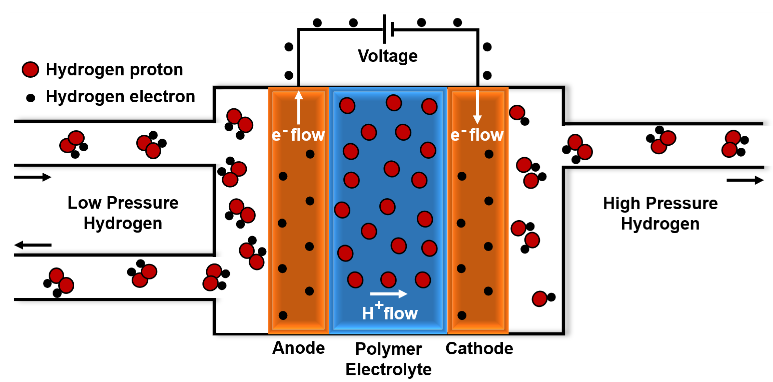
2. Electrochemical Hydrogen Compressor
The Electrochemical Hydrogen Compressor (EHC) has the same structure as a Proton Exchange Membrane Fuel Cell (PEM-FC). A membrane, positioned between two catalysts containing electrodes, acts as an electrolyte for protons exchange [25]. Hydrogen is oxidized at the anode and reduced at the cathode by a power supply: in this way, hydrogen is transferred from the low-pressure (LP) anodic compartment (Figure 1, left side) to the high-pressure (HP) cathodic compartment (Figure 1, right side).
Figure 1.
How an Electrochemical Hydrogen Compressor works: the polymer electrode membrane is positioned between two catalysts containing electrodes and allows the H2 protons to move from the left to the right side. H2 electrons flow in the same direction by a power supply. Then, at the cathode, the protons and electrons form hydrogen again, but at higher pressure.
Electrochemical reactions taking place in the process are [24]:
- ANODE: ;
- CATHODE: ;
- OVERALL REACTION: .
The hydrogen can be pressurized up to several hundred bars with a single cell [26]. Furthermore, the EHC operates hydrogen separation, compression, and purification in only one compact device.
The main components of an EHC stack are:
- MEA (Membrane Electrode Assembly), constituted by two (anodic and cathodic) electrodes, two (anodic and cathodic) catalyst layers, and a proton conductive membrane;
- bipolar plates, made of stainless steel. They contain the gas flow field;
- end-plates, made of stainless steel or carbon fiber composite;
- bolts. On the end-plates, they ensure the gas tightening of the system;
- gaskets.
3. Numerical Analysis
This study aims to optimize the design of an EHC single cell. In this case, the end-plates are monopolar plates, which means they contain the flow field only on their internal side. The analysis is organized into two steps:
- in the first step, different geometries of the monopolar plate are compared to identify the best configuration;
- once the best geometric configuration had been evaluated, the second part of the study concerned the design of the plate.
Simulations has been performed by Marc Software of MSC Software Corporation. MSC Marc finite elements approach is especially suitable for involving nonlinear aspects of the numerical analyses, such as contact, here modeled, or for future developments of the work, such as implicit elastoplastic simulations or damage, and cohesive zone method for modeling damage and fracture under limit conditions. The software also allows for easily customizing the mathematical modeling of the material’s response via very flexible Fortran user subroutines.
Geometric details, such as the channels of the flow-field, were not taken into account: they were replaced with a groove whose dimensions correspond to the active area (the area in which chemical reactions occur). The depth of the groove was calculated by summing:
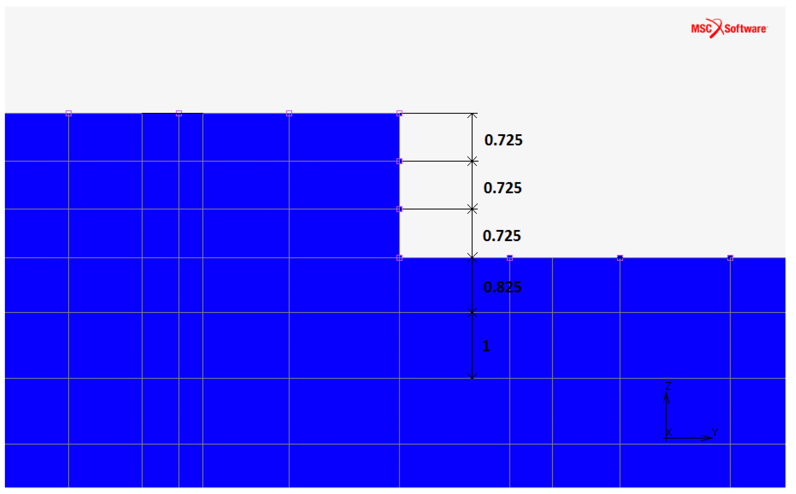
- the space for the MEA (overall thickness of , hence per plate);
- the depth the flow-field channels would have had if represented ( );
- corresponding to the thickness of a metallic mesh to put over the low-pressure channels to better support the MEA during operation.
The total depth of the groove is for the low-pressure side and for the high-pressure side. The FEM analyses were carried on for the low-pressure plate because they yielded a conservative estimate for the high-pressure plate.
The mesh was created manually along with the geometry using brick elements that have three degrees of freedom per node. Due to the high corrosiveness of the compression process, the chosen material was AISI 316 stainless steel (European designation: X5CrNiMo17-12-2/1.4401). It is an austenitic chromium-nickel stainless steel containing molybdenum; it has excellent ductility with high corrosion resistance and mechanical strength at elevated temperatures. Its elastic properties, listed in Table 1, have references in [27,28,29,30].
Table 1.
Elastic properties of AISI 316 stainless steel [27,28,29,30]: E is Young’s modulus, is the Poisson’s ratio, is the yield stress, is the Ultimate Tensile Strength and is the maximum Brinell Hardness. The first line contains the typical values; the second line reports the chosen values for the FEM simulations.
The working pressure of 700 bar acts on the upper side of the plate, inside the active area.
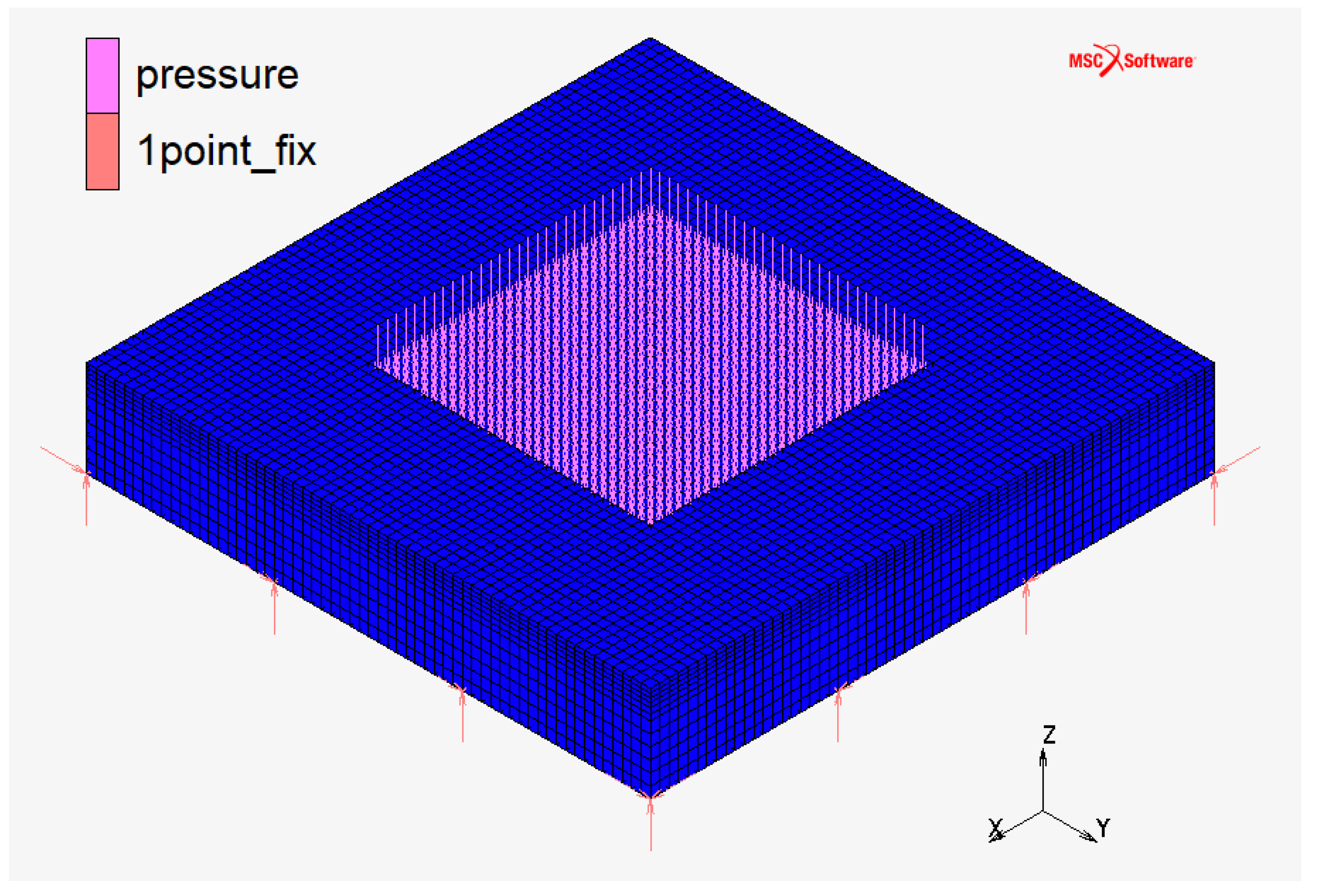
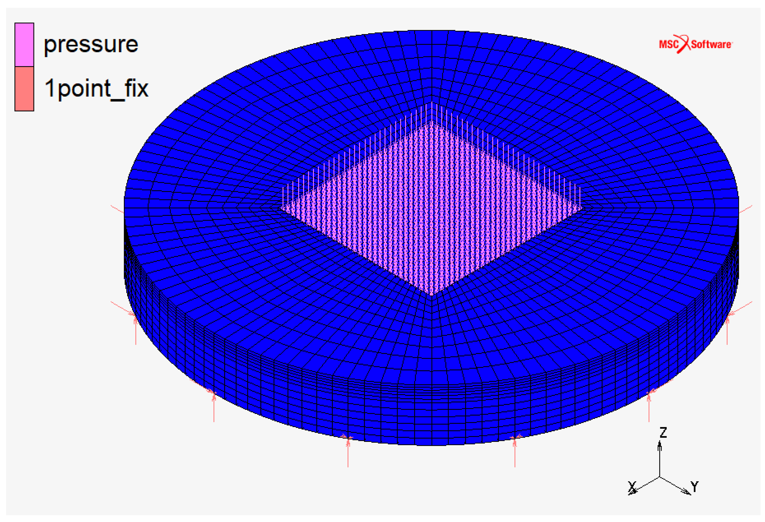
3.1. Part 1: Methodology
The diffusion of hydrogen within mechanical components made of stainless steel is known to induce the embrittlement phenomenon, consisting of the reduction of the plastic strains locally attainable before failure [12,13,14,15]. Consequently, the ultimate tensile stress and the fatigue response of stainless steel are negatively affected by pressure-driven diffusion of hydrogen within the alloy [14], while surface fracture can even be induced by cathodic charging with no outer stress applied [12]. In the application at hand, the contact between the surface of the compressor end-plates and the hydrogen flow is rather limited to the small-sized orifices and channels where the hydrogen is allowed to flow, so no large amounts of hydrogen can be expected to diffuse within the volume of the components. At the same time, such small-sized channels, holes, and irregular shape variations act as notches within the stressed mechanical component at hand, thus generating peaks of stress triaxiality, which further contribute to decreasing the ductility of metals at the local scale [31,32]. According to such considerations, the design of mechanical components to be continuously operated in hydrogen environments must be aimed at conservative levels of the nominal stress states. This is the reason why the stress states have been taken as the design parameter to be evaluated and designed by the finite element method for providing adequate structural integrity to the component.
FC monopolar and bipolar plates at the CNR laboratories utilize the configuration “a” represented in Figure 2: it has a squared plan view and squared active area (the area in which chemical reactions occur). This configuration is usually used in Fuel Cell applications because it maximizes the utilization of the active area. An axisymmetric geometry is more suitable for EHC application due to the high pressure on the active area. For this purpose, the comparison between three different geometric configurations (Figure 2, Figure 3 and Figure 4) was initially carried on.
Figure 2.
Monopolar plate—discretized domain in configuration “a”: squared plan view and squared active area.
Figure 3.
Monopolar plate—discretized domain in configuration “b”: circular plan view and squared active area.
Figure 4.
Monopolar plate—discretized domain in configuration “c”: circular plan view and circular active area.
The plate sizes were calculated starting from the FC monopolar plates used at the CNR laboratories with the following features:
- configuration “a”;
- square side of plan view: 100 ;
- square side of active area: 50 .
The other configurations have a circular plan view corresponding to the circle that circumscribes the square of the first configuration; a characteristic dimension greater than the one of case “a” (circle diameter against square side) was chosen to make the problem worse (larger size means much deflection). It was calculated as:
Finally, the circular active area of the last configuration corresponds to the circle that has the same area as the squared active area of the other two configurations:
About the sizing along the z-axis, the thickness of the plate is 30 for the three configurations. As stated above, the active area is deeper (Figure 5) than the plate surface.
Figure 5.
Monopolar plate—discretization along the z-axis in all the configurations (the dimension of each element is reported in ).
All the dimensions are summarized in Table 2.
Table 2.
Active area [] and characteristic dimensions [] of the three plate configurations: is the length (square side or diameter) of plate plan view, is the length (square side or diameter) of the active area, t is the thickness of the plate, and is the depth of the groove.
The comparison between geometries does not consider the bolts’ holes that ensure the system’s tightening: the plate was constrained by 3D pins placed at 12 points on the plate’s lower—not loaded—side. The number of 3D pins was chosen considering the perimeter of the plate.
3.2. Part 1: Results
Maximum values of deflection, equivalent strain, and Von Mises stress obtained from FEM simulations about the three configurations are reported in Table 3. The results show that configurations “b” and “c” have a significant decrease in deflection compared to the deflection of configuration “a”; in terms of strains and stresses, excluding the constrained points that distort the actual trend, a drastic increase occurs in configuration “b”, instead configuration “c” is the best in terms of stress.
Table 3.
Maximum values of deflection (), equivalent strain (), and Von Mises stress () for the three configurations.
Based on the results of this comparison, the plate’s design concerned the third configuration.
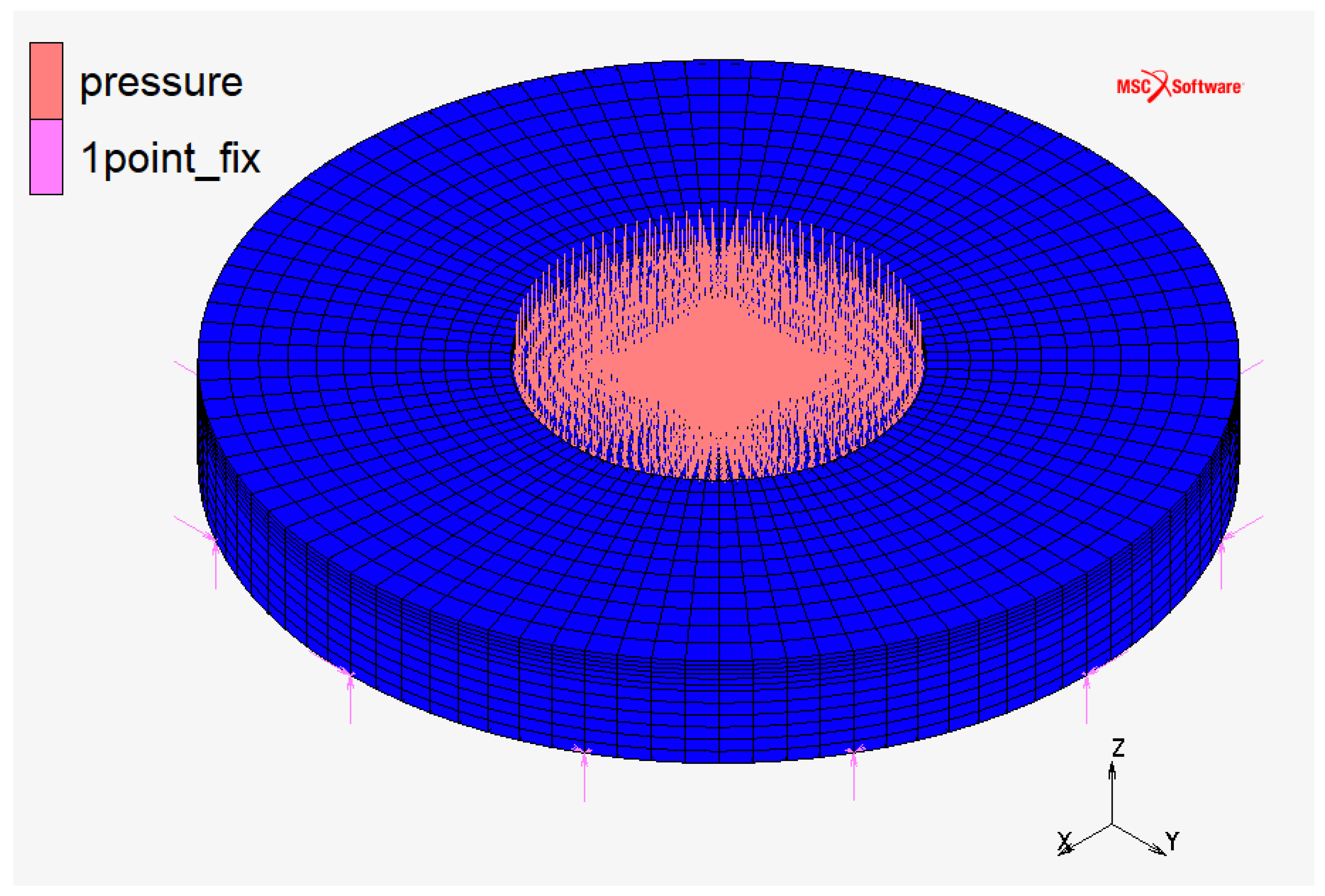
3.3. Part 2: Methodology
The goal of this work section was to size the monopolar plate (configuration “c”) to have a deflection no greater than when the EHC works at its operational pressure ( 700 ). This design value should ensure wide physical contact between the MEA and the high-pressure monopolar plate.
As the plate material and the number of constrained points cannot be changed, the only way to ensure a deflection lower than was to reduce the effective length of the plate as much as possible and to find its optimal (minimum) thickness. For this purpose, bolts’ holes and gasket’s groove that ensures the gas tightening of the system were taken into account.
Twelve high-strength M8 screws (class 10.9) with nuts and washers (with an external diameter of 16 ) were chosen. The minimum diameter of the screw was calculated as:
where:
- p is the pressure of 700 ;
- S is 2507 active area;
- n is the number of bolts;
- is a safety factor of 3;
- is the yield stress of the bolt material.
The gasket for the gas tightening of the EHC was chosen for axial load with internal pressure (Figure 6). In this condition, O-rings do not allow the use of Back-up Rings to avoid the extrusion of the gasket in the gap between the components to be connected. Instead, some metal rings, used as a deformable gasket in extreme static sealing situations, can increase their sealing capacity thanks to one or more coatings of materials, such as nickel, silver, gold, copper, and PTFE.
Figure 6.
A not-scale representation of the gasket closed groove: h is the groove depth, b is the groove width, and d is the groove diameter.
The metal ring was chosen to keep the groove width b as small as possible because it increases the plate’s effective length (Figure 6). The ring has a free height (cross-section diameter of the ring) of and an external diameter inside the range of . As reported in its technical data-sheet, the groove width is , while the groove depth is .
The external diameter of the groove was calculated as:
where is the active area diameter, 4 is the height of the membrane annulus that it was needed to add to the active area, and b is the groove width.
Once known the external diameter of the groove, it will be possible to calculate the external diameter of the metal ring as:
where is a clearance tolerance correction value, and is the maximum coating thickness if used.
The optimized sizing of the plate are shown in Figure 7. The thickness of the plate has been set to 17 because results will show that the deflection is less than .
Figure 7.
Optimized sizing of the plate: is the active area radius, 4 is the height of the membrane annulus added to the active area, is the groove width, 5 were left to give structural strength to the material before the 8 diameter holes for the bolts, 105 is the external diameter of the plate.
Once the geometry was defined, constraints were described more accurately than in the previous case to distribute contact stresses on a surface rather than in a point: both the body’s bolts and the washers were represented with infinitely rigid surfaces, the former with cylinders, the latter with circles. Constraints were represented as a touching contact between the deformable surface of the plate and the infinitely rigid surfaces of bolts and washers, ensuring that the surfaces were correctly oriented.
Additional nodes on the bottom surface of the plate were constrained to avoid plate rotation during the simulation; in particular, it was locked:
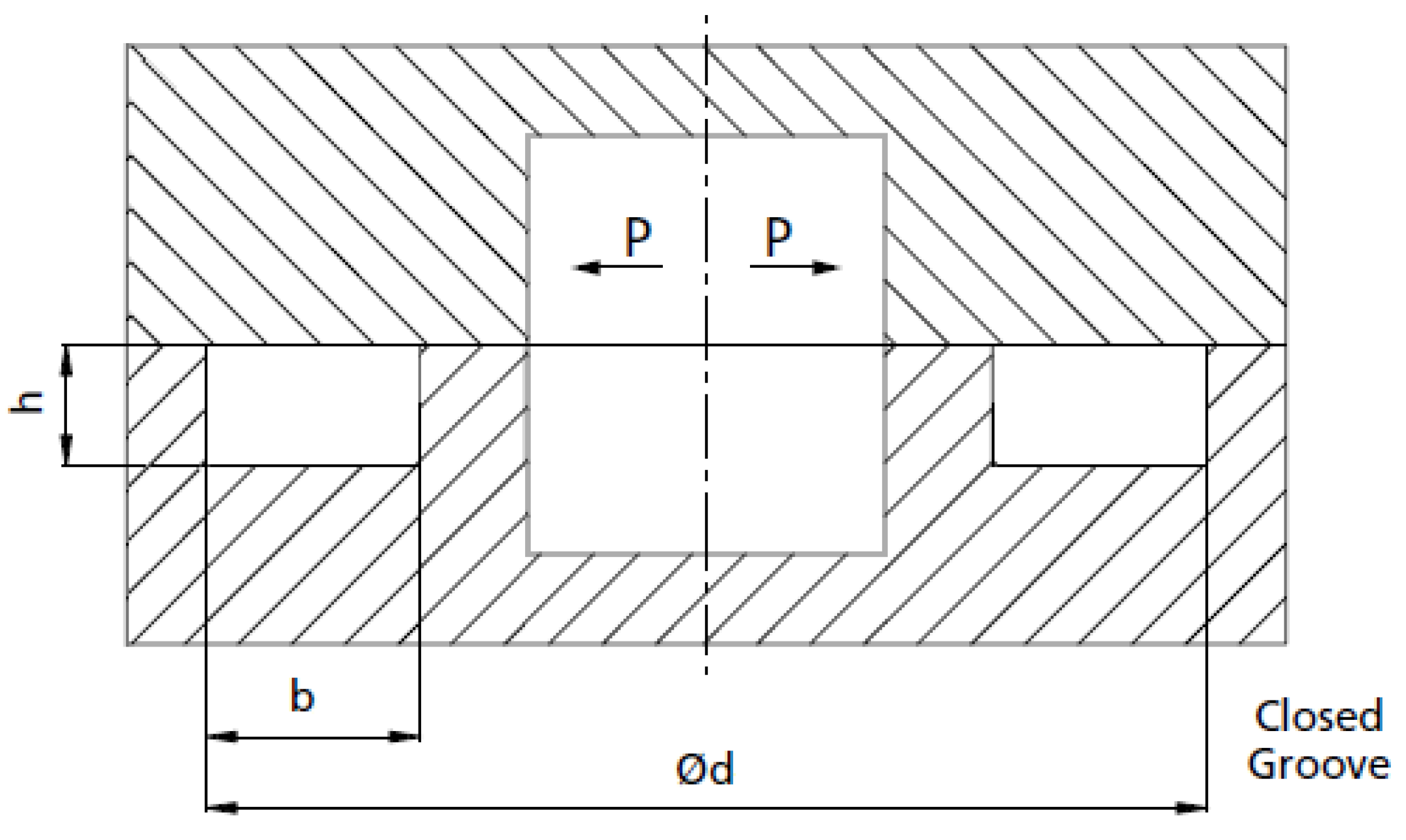
- central node displacements in XY plane;
- displacement of a y-axis point along the x-axis;
- displacement of an x-axis point along the y-axis.
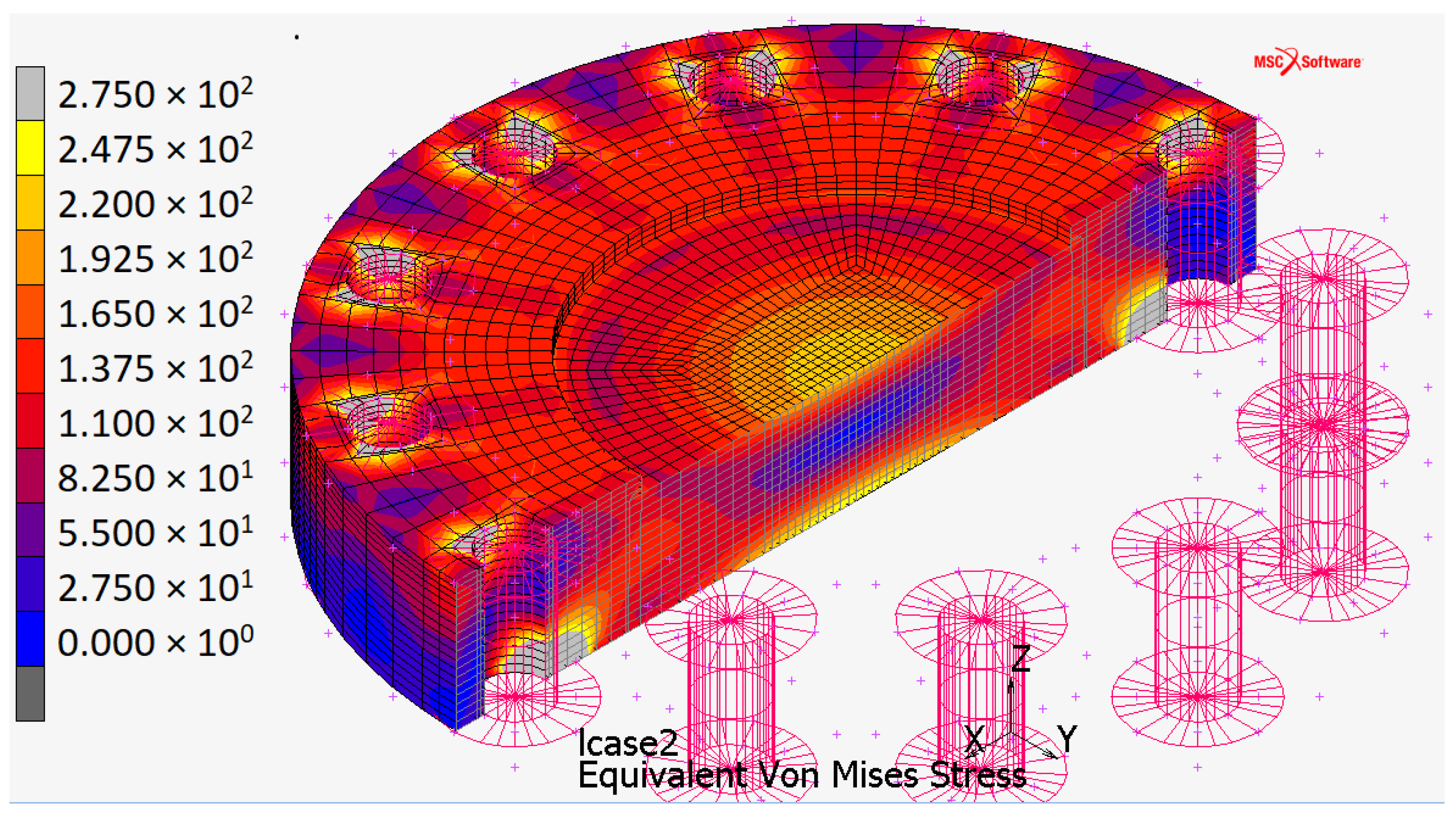
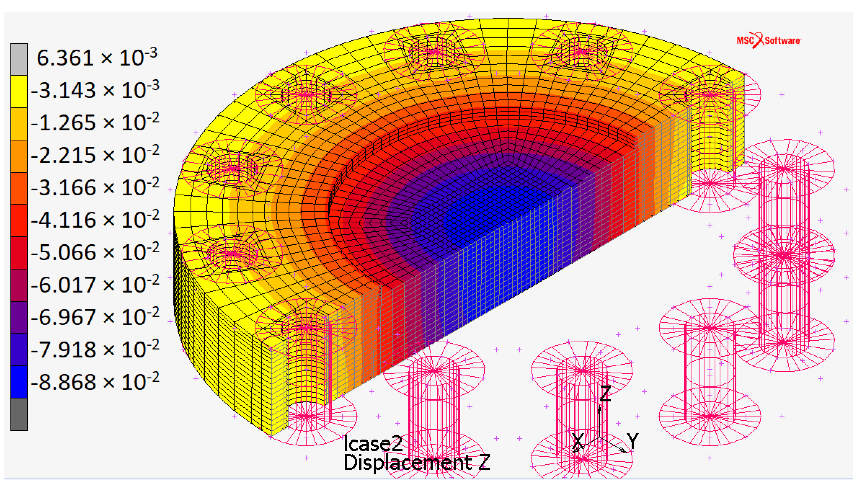
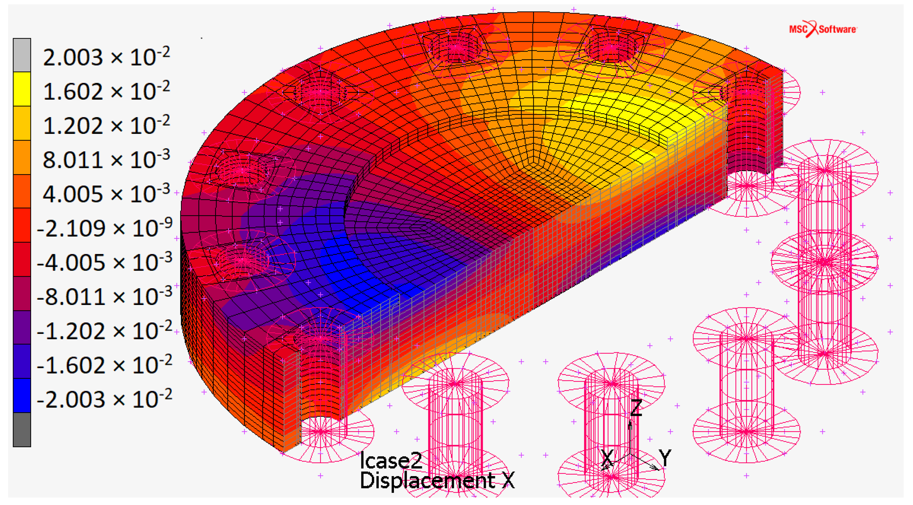
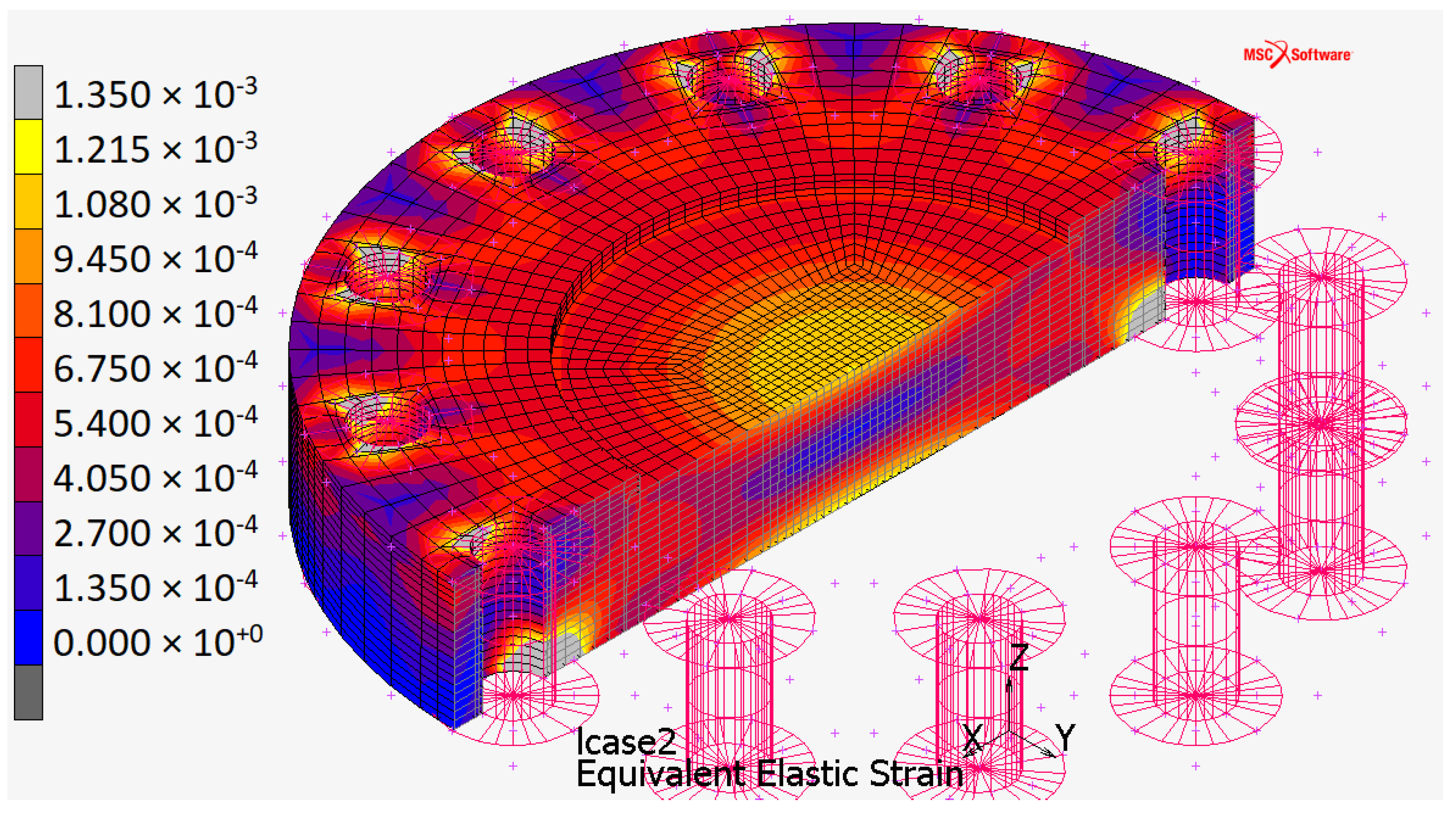
3.4. Part 2: Results
Figure 8, Figure 9, Figure 10 and Figure 11 shows the Von Mises stress, the deflection, the x-axis displacement, and the equivalent strain distributions.
Figure 8.
Von Mises stress distribution for the plate when constrained by touching contact with infinitely rigid surfaces.
Figure 9.
Deflection distribution for the plate when constrained by touching contact with infinitely rigid surfaces.
Figure 10.
x-axis displacement distribution (it is the same along the y-axis, 90 rotated) for the plate when constrained by touching contact with infinitely rigid surfaces.
Figure 11.
Equivalent strain distribution for the plate when constrained by touching contact with infinitely rigid surfaces.
The maximum stress (Figure 8) occurs:
- at the center of the plate (about 250 ) due to the high pressure applied orthogonally to the surface;
- in the contact areas (the automatic full-scale value, not represented in Figure 8, is ).
In both cases, stress values are higher than AISI 316 yield stress ( 200 , Table 1). Despite this, the plate still has an elastic behavior.
The first case is a hydrostatic compression that does not plasticize the material: the area with the maximum deflection is unloaded in the central axial view of the plate because it is compressed so much above, so much below. This fact avoids the plastic behavior of the material even under stresses that moderately exceed the yield strength without triggering pressure-dependent brittle failure issues.
In the second case, the stress is due to the Hertzian contact between the plate and the rigid surfaces. It must not be compared with the yield stress but with the maximum allowable surface pressure of the material (). As well as the maximum stress acts orthogonally to the center of the contact ellipse, the other two main stresses also act, preventing lateral deformation. Consequently the equivalent stress due to Hertzian contact pressures () is lower than the .
As and, according to [33], is only 63–65% :
Experimental relations link the maximum allowable surface pressure to the material hardness ( for AISI 316, see Table 1). One of these is [34]:
or [35]:
For AISI 316 is between 390 and 550 , higher than the equivalent stress .
The simulation did not consider the second monopolar plate of the EHC, and infinitely rigid surfaces of washers constrained the top surface of the plate. The FEM simulation without top washers showed a 3.13% increase in deflection; hence the actual displacement along the z-axis will be within the range [0%, 3.13%].
4. Conclusions and Future Work
This work analyzed the monopolar plate of an Electrochemical Hydrogen Compressor. Small-sized channels and holes behave as notches, significantly increasing the stress triaxiality at the local scale. High-stress triaxiality peaks, eventually combined with the hydrogen embrittlement, can significantly increase the probability of failure and crack initiation at a given material point.
Based on such considerations, the Electrochemical Hydrogen Compressor End-Plate must be designed to have conservative levels of the nominal stress states.
The present work aimed to find the optimal shape of the monopolar plate, starting from three different geometric configurations. The results of the FEM analysis with Marc software—of MSC Software Corporation—identified the optimal configuration in circular plan view and active area. The plate in this configuration has been sized to have a deflection no greater than when the EHC works at its operational pressure ( 700 ). The minimum plate thickness is 17 . The deflection can increase up to 3.13% as the upper surface of the plate has been constrained by infinitely rigid washers rather than the deformable surface of the other monopolar plate.
Future developments foresee realizing more accurate FEM simulations both on the monopolar plate and on the bipolar plate, involving new aspects, such as implicit elastoplastic simulations or damage both on a global scale (loads acting on the system are not the operating ones but the exceptional ones) and on a local scale (plasticization occurs even with standard loads, where the cracks appear).
Author Contributions
Conceptualization, R.C., E.P., G.M. and F.M.; Investigation, R.C., E.P. and G.M.; Methodology, F.M.; Software, E.P.; Writing—original draft, R.C., G.M. and F.M. All authors have read and agreed to the published version of the manuscript.
Funding
This research received no external funding.
Conflicts of Interest
The authors declare no conflict of interest.
References
- Niaz, S.; Manzoor, T.; Pandith, A. Hydrogen storage: Materials, methods and perspectives. Renew. Sustain. Energy Rev. 2015, 50, 457–469. [Google Scholar] [CrossRef]
- Durbin, D.; Malardier-Jugroot, C. Review of hydrogen storage techniques for on board vehicle applications. Int. J. Hydrogen Energy 2013, 38, 14595–14617. [Google Scholar] [CrossRef]
- Casati, C.; Longhi, P.; Zanderighi, L.; Bianchi, F. Some fundamental aspects in electrochemical hydrogen purification/compression. J. Power Sources 2008, 180, 103–113. [Google Scholar] [CrossRef]
- Barthelemy, H.; Weber, M.; Barbier, F. Hydrogen storage: Recent improvements and industrial perspectives. Int. J. Hydrogen Energy 2017, 42, 7254–7262. [Google Scholar] [CrossRef]
- Seayad, A.; Antonelli, D. Recent Advanced in Hydrogen Storage in Metal-Containing Inorganic Nanostructures and Related Materials. Adv. Mater. 2004, 16, 765–777. [Google Scholar] [CrossRef]
- Rusman, N.; Dahari, M. A review on the current progress of metal hydrides material for solid-state hydrogen storage applications. Int. J. Hydrogen Energy 2016, 41, 12108–12126. [Google Scholar] [CrossRef]
- Niemann, M.U.; Srinivasan, S.S.; Phani, A.R.; Kumar, A.; Goswami, D.Y.; Stefanakos, E.K. Nanomaterials for Hydrogen Storage Applications: A Review. J. Nanomater. 2008, 2008, 950967. [Google Scholar] [CrossRef] [Green Version]
- Hua, T.; Ahluwalia, R.; Peng, J.; Kromer, M.; Lasher, S.; McKenney, K.; Law, K.; Sinha, J. Technical assessment of compressed hydrogen storage tank systems for automotive applications. Int. J. Hydrogen Energy 2011, 36, 3037–3049. [Google Scholar] [CrossRef] [Green Version]
- Ahluwalia, R.; Hua, T.; Peng, J. On-board and Off-board performance of hydrogen storage options for light-duty vehicles. Int. J. Hydrogen Energy 2012, 37, 2891–2910. [Google Scholar] [CrossRef]
- Bouwman, P. Electrochemical Hydrogen Compression (EHC) solutions for hydrogen infrastructure. Fuel Cells Bull. 2014, 2014, 12–16. [Google Scholar] [CrossRef]
- Miguel, N.; Cebolla, R.O.; Acosta, B.; Moretto, P.; Harskamp, F.; Bonato, C. Compressed hydrogen tanks for on-board application: Thermal behaviour during cycling. Int. J. Hydrogen Energy 2015, 33, 6449–6458. [Google Scholar] [CrossRef]
- Eliezer, D. The Behavior of 316 Stainless Steel in Hydrogen. J. Mater. Sci. 1984, 19, 1540. [Google Scholar] [CrossRef]
- Zhou, X.; Tehranchi, A.; Curtin, W.A. Mechanism and Prediction of Hydrogen Embrittlement in fcc Stainless Steels and High Entropy Alloys. Phys. Rev. Lett. 2021, 127, 175501. [Google Scholar] [CrossRef] [PubMed]
- Ogata, T. Influence of high pressure hydrogen environment on tensile and fatigue properties of stainless steels at low temperatures. AIP Conf. Proc. 2012, 1435, 39–46. [Google Scholar] [CrossRef] [Green Version]
- Omura, T.; Nakamura, J. Hydrogen Embrittlement Properties of Stainless and Low Alloy Steels in High Pressure Gaseous Hydrogen Environment. ISIJ Int. 2012, 52, 234–239. [Google Scholar] [CrossRef] [Green Version]
- Suermann, M.; Kiupel, T.; Schmidt, T.J.; Büchi, F.N. Electrochemical Hydrogen Compression: Efficient Pressurization Concept Derived from an Energetic Evaluation. J. Electrochem. Soc. 2017, 164, F1187–F1195. [Google Scholar] [CrossRef]
- Besancon, B.M.; Hasanov, V.; Imbault-Lastapis, R.; Benesch, R.; Barrio, M.; Mølnvik, M.J. Hydrogen quality from decarbonized fossil fuels to fuel cells. Int. J. Hydrogen Energy 2009, 34, 2350–2360. [Google Scholar] [CrossRef]
- Strobel, R.; Oszcipok, M.; Fasil, M.; Rohland, B.; Jorissen, L.; Garche, J. The compression of hydrogen in an electrochemical cell based on a PE Fuel Cell design. J. Power Sources 2002, 105, 208–215. [Google Scholar] [CrossRef]
- Zou, J.; Han, N.; Yan, J.; Feng, Q.; Wang, Y.; Zhao, Z.; Fan, J.; Zeng, L.; Li, H.; Wang, H. Electrochemical Compression Technologies for High-Pressure Hydrogen: Current Status, Challenges and Perspective. Electrochem. Energy Rev. 2020, 3, 690–729. [Google Scholar] [CrossRef]
- Matera, F.; Gatto, I.; Saccà, A.; Carbone, A.; Pedicini, R. Performance assessment of alternative membranes for Electrochemical Hydrogen Compressor (EHC) in portable PEM fuel cell applications. In Proceedings of the European Hydrogen Energy Conference, Malaga, Spain, 14–16 March 2018. [Google Scholar]
- Rohland, B.; Eberle, K.; Strobel, R.; Scholta, J.; Garche, J. Electrochemical hydrogen compressor. Electrochim. Acta 1998, 43, 3841–3846. [Google Scholar] [CrossRef]
- Arvay, A. Proton Exchange Membrane Fuel Cell Modeling and Simulation Using Ansys Fluent; Arizona State University: Tempe, AZ, USA, 2011. [Google Scholar]
- Baker, J.; Hwang, Y.; Wang, C. Design of Gas Channels for a Carbon Dioxide Electrochemical Compressor. In Proceedings of the International Compressor Engineering Conference, West Lafayette, IN, USA, 9–12 July 2018; p. 2616. [Google Scholar]
- Grigoriev, S.; Shtatniy, I.; Millet, P.; Porembsky, V.; Fateev, V. Description and characterization of an electrochemical hydrogen compressor/concentrator based on solid polymer electrolyte technology. Int. J. Hydrogen Energy 2011, 36, 4148–4155. [Google Scholar] [CrossRef]
- Bampaou, M.; Panopoulos, K.; Papadopoulos, A.; Seferlis, P.; Voutetakis, S. An Electrochemical Hydrogen Compression Model. Ital. Assoc. Chem. Eng. 2018, 70, 1213–1218. [Google Scholar]
- Grigoriev, S.; Djous, K.; Millet, P.; Kalinnikov, A.; Porembskiy, V.; Fateev, V.; Blach, R. Characterization of PEM Electrochemical Hydrogen Compressors; Kurchatov Institute: Moscow, Russia, 2008. [Google Scholar]
- Available online: https://www.acciaiterni.it/wp-content/uploads/2017/07/316_NEW.pdf (accessed on 30 May 2022).
- Available online: http://www.ambrogiocolombo.it/prodotto/inox-aisi-316/ (accessed on 30 May 2022).
- Available online: https://www.gruppolimainox.it/index.php/attivita/114-pages/acciai-inossidabili/designazione/317-aisi-316 (accessed on 31 May 2022).
- Available online: https://www.efunda.com/Materials/alloys/stainless_steels/show_stainless.cfm?ID=AISI_Type_316&prop=all&Page_Title=AISI%20Type%20316 (accessed on 31 May 2022).
- Mirone, G. Role of stress triaxiality in elastoplastic characterization and ductile failure prediction. Eng. Fract. Mech. 2007, 74, 1203–1221. [Google Scholar] [CrossRef]
- Peng, J.; Wang, Y.; Dai, Q.; Liu, X.; Liu, L.; Zhang, Z. Effect of Stress Triaxiality on Plastic Damage Evolution and Failure Mode for 316L Notched Specimen. Metals 2019, 9, 1067. [Google Scholar] [CrossRef] [Green Version]
- Giovannozzi, R. Costruzione di Macchine; Pàtron: San Francisco, CA, USA, 1980; Volume 1. [Google Scholar]
- Righettini, P. Available online: https://docplayer.it/57127739-Progettazione-funzionale-di-sistemi-meccanici-e-meccatronici-camme-pressioni-di-contatto.html (accessed on 19 January 2022).
- Available online: https://web.archive.org/web/20210301070357/http://mechdesigner.support/index.htm?contact-fatigue-cams-cam-followers.htm (accessed on 19 January 2022).
Publisher’s Note: MDPI stays neutral with regard to jurisdictional claims in published maps and institutional affiliations. |
© 2022 by the authors. Licensee MDPI, Basel, Switzerland. This article is an open access article distributed under the terms and conditions of the Creative Commons Attribution (CC BY) license (https://creativecommons.org/licenses/by/4.0/).