Review

Hydrogen Storage in Geological Formations—The Potential of Salt Caverns

by
Aleksandra Małachowska
1,
Natalia Łukasik
2,*,
Joanna Mioduska
1,* and
Jacek Gębicki
1,*
1
Department of Process Engineering and Chemical Technology, Faculty of Chemistry, Gdańsk University of Technology, 11/12 Narutowicza Street, 80-233 Gdansk, Poland
2
Department of Chemistry and Technology of Functional Materials, Faculty of Chemistry, Gdańsk University of Technology, 11/12 Narutowicza Street, 80-233 Gdansk, Poland
*
Authors to whom correspondence should be addressed.
Energies 2022, 15(14), 5038; https://doi.org/10.3390/en15145038
Submission received: 2 June 2022 / Revised: 30 June 2022 / Accepted: 7 July 2022 / Published: 10 July 2022

Abstract

:
Hydrogen-based technologies are among the most promising solutions to fulfill the zero-emission scenario and ensure the energy independence of many countries. Hydrogen is considered a green energy carrier, which can be utilized in the energy, transport, and chemical sectors. However, efficient and safe large-scale hydrogen storage is still challenging. The most frequently used hydrogen storage solutions in industry, i.e., compression and liquefaction, are highly energy-consuming. Underground hydrogen storage is considered the most economical and safe option for large-scale utilization at various time scales. Among underground geological formations, salt caverns are the most promising for hydrogen storage, due to their suitable physicochemical and mechanical properties that ensure safe and efficient storage even at high pressures. In this paper, recent advances in underground storage with a particular emphasis on salt cavern utilization in Europe are presented. The initial experience in hydrogen storage in underground reservoirs was discussed, and the potential for worldwide commercialization of this technology was analyzed. In Poland, salt deposits from the north-west and central regions (e.g., Rogóźno, Damasławek, Łeba) are considered possible formations for hydrogen storage. The Gubin area is also promising, where 25 salt caverns with a total capacity of 1600 million Nm3 can be constructed.

1. Introduction

Climate change and the associated consequences such as the global temperature increase, melting of arctic ice, and acidification of oceans are alarming threats to the whole world. Observed changes are associated, among other things, with the emission of greenhouse gases, which for instance, in Poland in 2018 was estimated as 413 million tonnes of CO2 equivalent, of which 48% was from the energy sector and 19% from transportation [1]. Since many environmental risks have an anthropogenic source, decisive and realistic actions must be taken to facilitate sustainable development and wellbeing. One of the possible solutions is the transition from fossil fuels-based industry toward low-emission technologies. Under the Paris Agreement signed in 2015, many countries, including Poland, were obliged to significantly reduce greenhouse gas emissions by the second half of this century [2]. To meet these expectations, the global trend of climate policy is aimed at increasing the share of electricity from renewable sources. The reflection of this strategy can be found among the postulates of the European Green Deal established by the European Commission (EC) in 2019 [3]. According to WindEurope report, wind plants of 220 GW total capacity were installed in Europe till 2020, 89% of which were onshore installations [4]. In Poland, the estimated share of energy from renewable sources in gross final energy consumption was determined as around 12% in 2019, and is expected to increase [5]. The utilization of wind turbines or solar panels seems to be a promising solution, however, the major problem is that energy generation is not correlated with energy consumption, but strongly depends on the weather, geographical localization, day time, and season. To offset the mismatch between the fluctuating energy production and demand, effective energy storage technologies for a periods of overproduction and reuse during a period of shortage is needed. According to the EC, a major role in the transformation of the European energy market will play hydrogen-involving technologies. Thus, in July 2020, “A hydrogen strategy for a climate-neutral Europe” was published [6], where a roadmap for the European Union (EU) climate neutrality was proposed. The strategy is mainly based on the power to gas concept (P2G), which concerns electric energy conversion to hydrogen through water electrolysis. The obtained gas can be then stored and reconverted into electricity when needed. In comparison to either pumped hydro-energy storage (PHES) or compressed air-energy storage (CAES), P2G is characterized by a longer storage period (days to months) and high volumetric energy density [7], having the potential for large-scale energy storage (TWh range) [8,9]. Thus, the objective in the first phase of the EC plan (years 2020–2024) is the installation of at least 6 GW of renewable hydrogen electrolyzers producing up to 1 million tonnes of renewable hydrogen. In the second phase (years 2025–2030), the numbers are planned to be increased up to 40 GW and 10 million tonnes, respectively [6]. In response to the EU trends, the Polish Ministry of Climate and Environment presented the Polish hydrogen strategy in January 2021, aiming to create a hydrogen economy for the energy, transportation, and industrial sector [10]. Currently, Poland is among the global leaders in hydrogen production (1 million tonnes per year) [11], which is mostly utilized by the refining sector. According to the strategy, hydrogen will be a key pillar of industry decarbonization, serving not only as a green energy vector and fuel in hydrogen-powered vehicles but also as a possibility of energy independence in case of the depletion of fossil fuels deposits [10]. The development of hydrogen technologies may also significantly influence the strengthening of the economy due to the creation of new jobs [12].
The increased importance of hydrogen in the zero-emission scenario for Poland and the whole EU requires a safe and efficient gas storage method. Recently, several physical and chemical hydrogen storage methods have been proposed [13]. Among them, the physical storage of gaseous hydrogen in pressure tanks (up to 700 atm) and liquid hydrogen in cryo tanks (at a temperature of −253 °C) are the most frequently used in industrial practice [14]. The general information about hydrogen storage technologies is summarized in Table 1 [14,15,16].
Taking into account the planned scale of hydrogen production in the near future, underground storage is considered the safest and most economical option [17,18]. Compared to aboveground gas storage, it is better protected against external influences (e.g., fire, military actions, terrorist attacks, and others) because of overlying geological layers. It provides greater storage pressure and thus higher energy density, a smaller surface footprint, and lower specific investment costs than surface storage [7,19]. Among geological formations, natural water-bearing reservoirs (aquifers), depleted oil and gas fields, abandoned underground mines or rock caverns excavated using conventional mining techniques, and man-made salt caverns are assumed to be ideal for underground hydrogen storage [20,21,22]. The latter seem to be the most promising for seasonal energy storage due to the favorable mechanical properties and low permeability of salt rocks, preventing hydrogen losses [18]. However, as suitable rock salt formations are distributed irregularly, successful underground storage strongly depends on localization.
This review aimed to present the current state of knowledge on the potential of underground hydrogen storage, emphasizing salt caverns in Europe and Poland as regions of great potential. Among the many challenges concerning geological hydrogen storage, suitable site selection is one of the most crucial. Although more and more attention is being paid to this type of H2 storage, the commercialization of this technology is still in its infancy. Thus, further research and development are required. The motivation of this paper was to assess which salt deposits in Poland are suitable for potential hydrogen storage. Although many valuable works were described [9,23,24], an up-to-date summary of knowledge is still required.

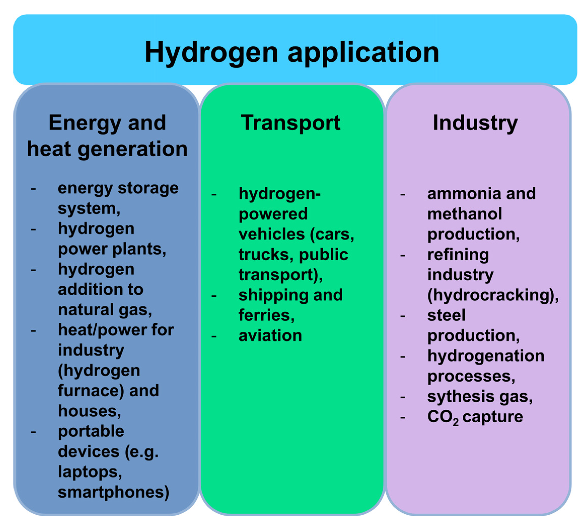
2. Hydrogen as an Energy Carrier

The growing interest in hydrogen technologies results from the possibility of using hydrogen as an energy buffer, which may provide promising results in the future of the energy sector in Europe [16,25]. In the P2G system, the gas obtained in electrolysis can be stored underground and, according to need, used to produce electricity in a gas power plant, as a fuel in hydrogen-powered vehicles or as feedstock in the chemical and refining industry [17]. Although the overall efficiency of P2G technology ranges from 40 to 60% (depending on an operational mode) [17,26], hydrogen is considered a promising energy carrier due to its transporting and sorting energy capacities.
Hydrogen is the lightest and simplest element, consisting of one proton and one electron, and is one of the most abundant (as a part of diverse chemical compounds) in the universe. As early as 1997, Daimler–Chrysler used compressed hydrogen as a fuel cell in car prototypes [27,28]. Today, this technology is CO2-free as only water is obtained as a product, which is important for the decarbonization of the transportation sector [9,27]. However, effective hydrogen storage is challenging. The main reason for this is the low density of hydrogen under standard conditions, where 1 kg of gas occupies a volume of 11 m3 [9]. Compressing or cooling hydrogen below its critical temperature increases its density; however, both operations are energy-consuming. Small size and low dynamic viscosity favor gas permeability and may result in hydrogen losses during storage. At high temperatures and pressures, it diffuses in steel causing hydrogen embrittlement and corrosion [29]. All issues mentioned above need to be considered when designing the storage system.
Hydrogen is referred to as an inexhaustible carrier of energy [25,28], so the future of the energy economy may be based on the use of hydrogen energy, which significantly reduces the emissions of harmful gases into the air and provides security of the energy supply [16,25,30]. Iceland wants to use its potential to increase the hydrogen share in energy production and to replace traditional fuels with hydrogen over time. Canada and Japan are the major hydrogen giants. Canada’s activities focus on strengthening its position in the context of fuel cells, while increasing public awareness of renewable fuels and their benefits. In the US, one of the reasons for investing in hydrogen has been air quality restrictions. Hydrogen is considered as low or even zero-emission fuel; therefore, interest in hydrogen has increased in the transport sector (hydrogen-powered cars, hydrogen station infrastructure, and development of education in this direction) [25,28].
Hydrogen-based transport is also developing rapidly in Japan, which is the producer of some of the most popular car brands including Toyota, Honda, and Nissan. The main reason for the implementation of the hydrogen policy in Japan was the country’s desire to become independent in terms of energy. According to Johnston [28], in 2001, imported oil accounted for over 88% of Japan’s energy. Japan also implemented a three-year project to use fuel cells to power more than a dozen homes. Germany uses hydrogen as a fuel in cars and city transport, but also in vehicles serving the airport (Munich). The infrastructure of hydrogen stations is also constantly developing [28].
A promising direction for hydrogen generation is the biological treatment of wastewater (photofermentation, biophotolysis, heterotrophic fermentation). This method will allow the efficient use of wastewaters, while producing hydrogen at the same time, which is another step in caring for the environment. Kothari [31] stated that hydrogen energy can be obtained from fermentation by transferring up to 40% of the chemical energy stored in wastewater.
Hydrogen shows potential for use in various sectors (Figure 1) [6,10]. Today, gas is used in industrial processes (refining, chemistry, steel production), fertilizers production, cooling in power plants, semiconductor manufacturing, and food processing. Metal hydride batteries are already used as batteries in electronic devices (e.g., laptops). Due to the high consumption of fossil fuels and increasing environmental awareness, hydrogen is currently considered as the most promising fuel for the future. It is considered that sooner rather than later, hydrogen will be used for supplying electricity and heat to residents as well as in transportation (road, water, and air), with little or no environmental impact, both locally and globally.

3. Experience in Underground Storage

Experience gained in the underground storage of gases such as natural gas, and carbon dioxide can be used in the development of efficient and safe hydrogen storage. Geological structures are used extensively in the oil and gas industries, especially when compressed air energy is considered. In 1915, the first successful underground storage of natural gas took place in a partially depleted reservoir of gas in Ontario, Canada [32]. Among natural gas storage installations that are run globally, most are located in depleted hydrocarbons and gas deposits (around 70%), in salt caverns, and less often in deep aquifers [33]. The injection of carbon dioxide into underground formations has been practiced for many years in the oil sector for enhanced oil recovery [34,35]. Nowadays, it is also one of the methods used for the reduction of CO2 emissions [36]. The most promising reservoirs for CO2 storage are saline aquifers and depleted gas and oil deposits [37]. On the European market, Germany has the largest number of caverns, which also translates into the largest storage potential (9.4 PWhH2), taking into account both land and sea deposits [24]. Caverns in Germany are drilled at depths from 500 to 2000 m below the surface, with heights reaching up to about 400 m. The operating pressure in such caverns is 200 bar [38]. Some of these facilities are now considered potential hydrogen storage systems (e.g., salt caverns located in the northern Nordrhein-Westfalen region), for which the total hydrogen storage capacity is estimated as 8.8 billion m3 (26.5 TWh) [39]. Although some similarities between natural gas and hydrogen storage technologies exist, underground hydrogen storage is much more complex [40]. The main differences come from the physiochemical properties of hydrogen and methane (the main component of natural gas), which require special attention. The smaller size and lower viscosity of hydrogen compared to methane may bring leaking problems. Under standard conditions, hydrogen has almost a three times higher diffusion coefficient in water compared to methane. Better chemical activity of hydrogen may result in hydrogen losses due to chemical reactions between the gas and substances present in an underground storage system. Hydrogen embrittlement may reduce metals’ durability, especially under a high hydrogen concentration and increased pressure [9]. Moreover, it is characterized by a high energy content per mass of 143 MJ kg−1, which is around three times higher than for gasoline which means that it can reach a range similar to gasoline and high-pressure vehicles (Table 2) [27,41]. A comparison of the selected physiochemical properties of hydrogen and methane can be found in Table 2 [9,16,42]. The technologies of geological CO2 storage cannot also be implemented directly in hydrogen storage due to the significant differences in the physicochemical properties of these gases. Higher carbon dioxide solubility in water than hydrogen (0.169 g/100 g vs. 0.00016 g/100 g, respectively [43]) results in altering the reservoir mineralogy by changing the pH (due to formation of carbonic acid) and ion concentration in the brine (present in saline aquifers and salt caverns) [44,45].
Some experience can also be gained from the storage of town gas. It contains 50–60% hydrogen and other components are as follows: carbon mono- and dioxide, methane, and nitrogen [9]. The town gas (coal gas), obtained in coal coking, was utilized in Europe in the second half of the 19th century before it was replaced by natural gas. It was successfully stored in aquifers in Germany (Engelbosten and Bad Lauchstädt), France (Beyens), and the Czech Republic (Lobodice) [42]. However, experience with town gas storage in the Czech Republic revealed that after several months of storage, almost 50% of hydrogen was lost [46]. It was explained that in the presence of methanogenic bacteria, hydrogen is transformed into methane through the Sabatier methanogenic reaction [47]:
4 H2 + CO2 ⇄ CH4 + 2 H2O
Methanogenesis occurs under optimal conditions of 90 bar pressure and a temperature range of 30–40 °C in the subsurface [48]. In the presence of carbon dioxide, hydrogen can also be converted to acetic acid (acetogenesis) [49], whereas sulfate- and iron-reducing bacteria induce hydrogen transformation into hydrogen sulfide and water, respectively [50]. Thus, microbiological activity in underground reservoirs is another issue that needs to be addressed, in order to ensure safe and effective hydrogen storage.
Currently, there are just a few examples of successful pure hydrogen storage worldwide. All of them include storage in salt caverns. Since 1972 in the UK (Teesside in Yorkshire), the Sabic Petroleum company has been storing almost pure hydrogen (95% of H2, 3–4% of CO2) in three shallow salt caverns (at a depth of ca. 400 m), each of which has a capacity of around 70,000 m3 of hydrogen at 45 bar [19,32,51]. The caverns are operated at a constant pressure. Gas displaces with a brine from surface ponds, acting as a buffer in the ammonia and methanol production plants [7,9]. In Texas, USA, three deeper located caverns are operated by ConocoPhillips (Clemens), Praxair (Moss Bluff), and Air Liquide (Spindletop), and they are utilized in the petrochemical industry [7]. Their dimensions and shape basically correspond to that of modern natural gas caverns. For instance, the Clemens salt dome has a cylindrical shape. It is 300 m high and has a diameter of 49 m [9]. The newest Spindletop cavern (operating since around 2017) is currently the largest hydrogen storage facility in the world. The cavern in Moss Bluff is connected to the Praxair Gulf Coast pipeline network with a total length of several hundred kilometers, covering the hydrogen demands of Texas and Louisiana [7,9]. Despite almost 40 years of experience, the American technology cannot be taken over in Europe one-to-one due to differences in safety regulations [19]. The caverns for hydrogen storage in Europe will have to be adapted to the specifications determined for natural gas storage [7]. More detailed information about the hydrogen storage caverns can be found in Table 3 [7,9,19].

4. Underground Geological Formations with the Potential to Hydrogen Storage

The main options for the deep underground storage of gases in geological formations are:
  • Natural water-bearing reservoirs (aquifers);
  • Abandoned underground mines;
  • Depleted gas and oil fields;
  • Rock caverns being excavated using conventional mining techniques;
  • Man-made salt caverns [22].
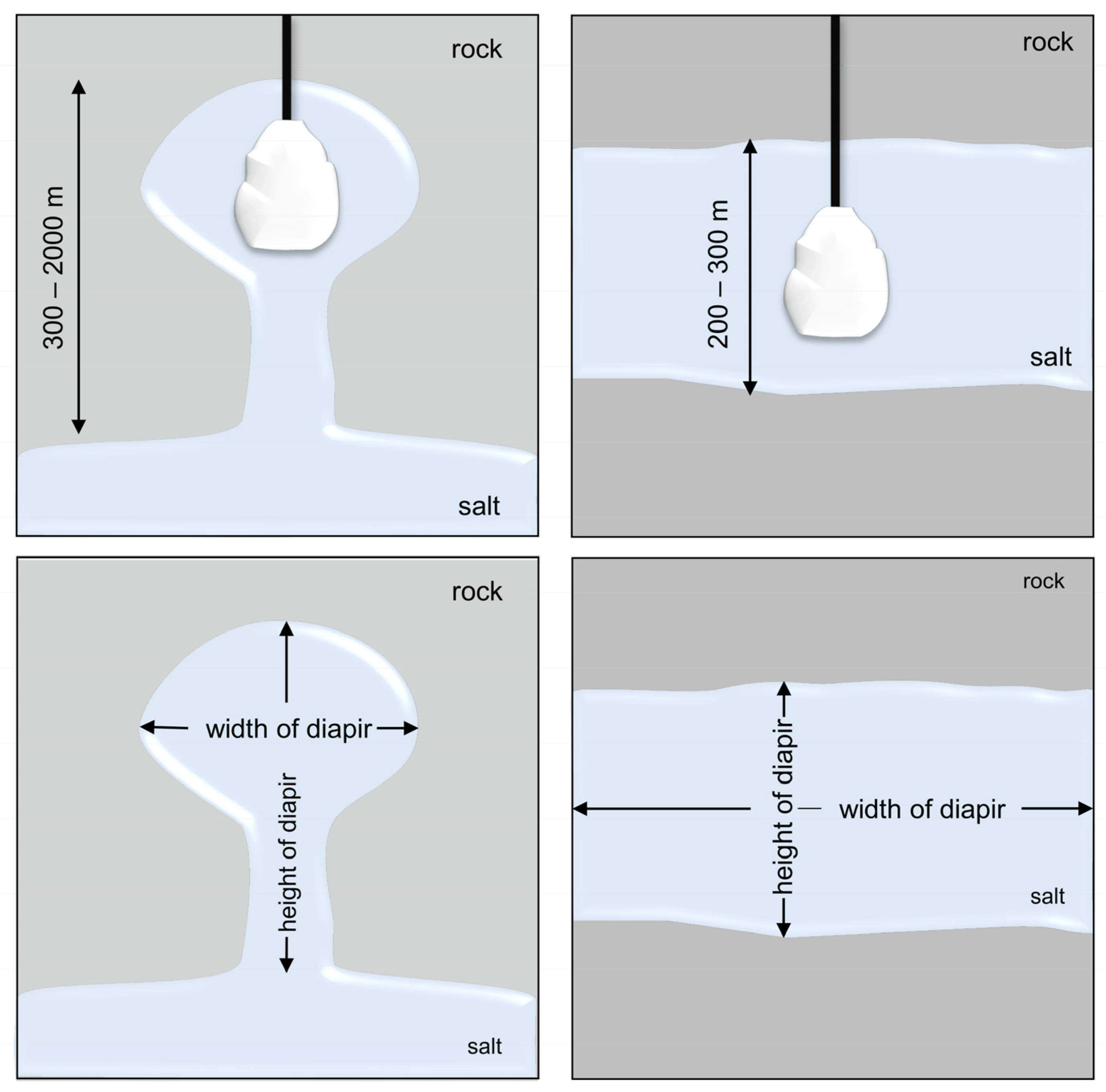
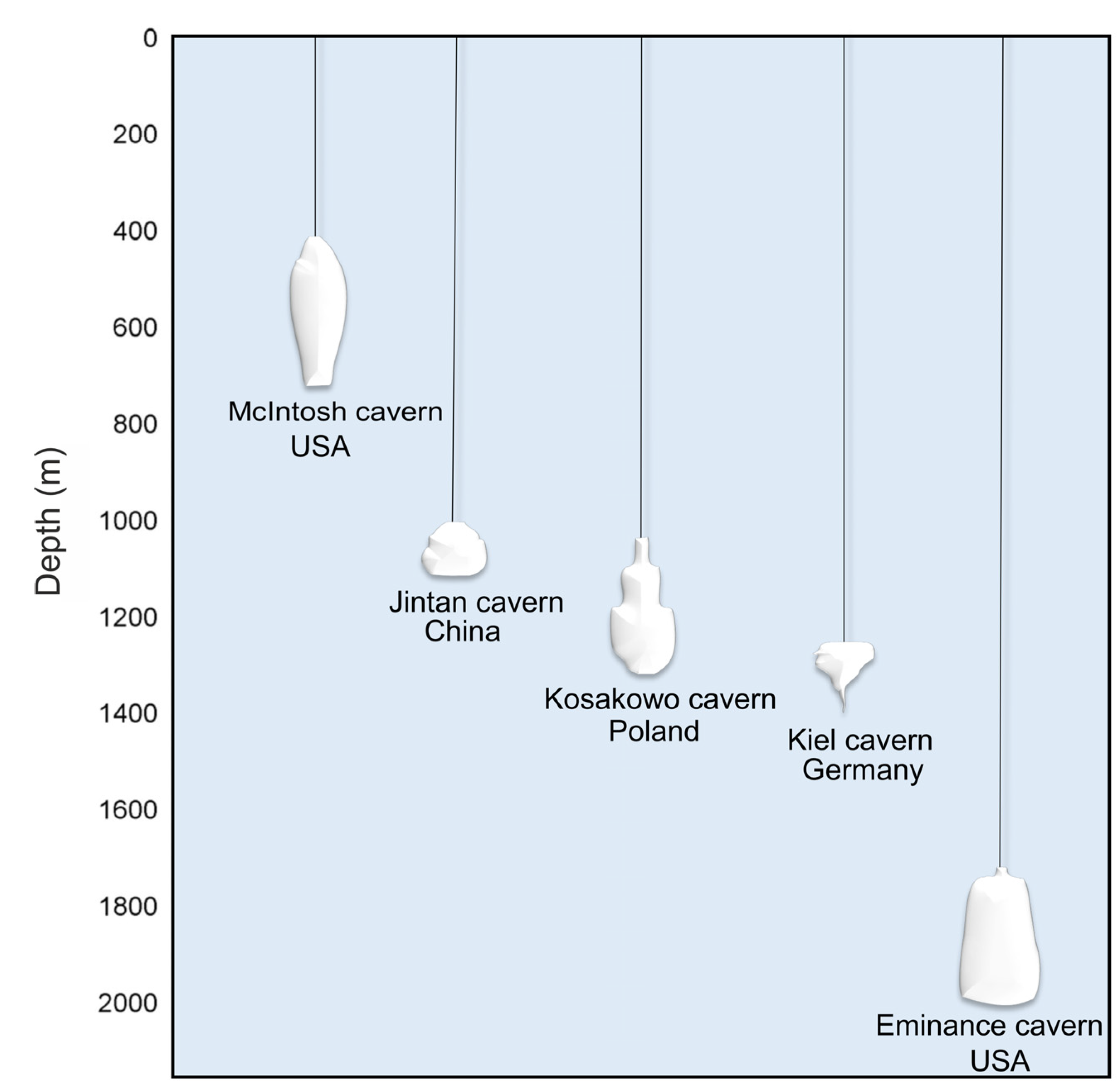
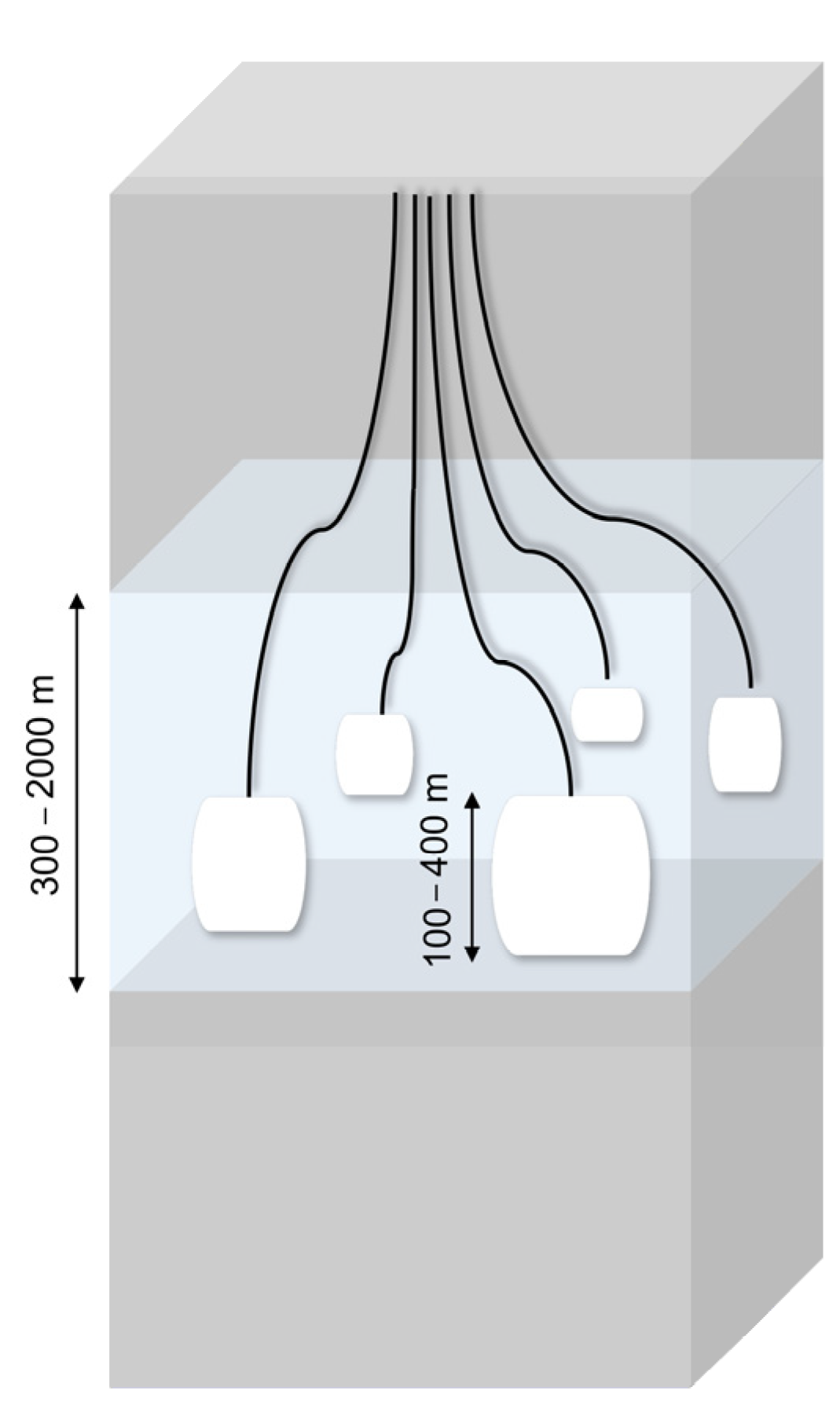
Various types of geological formations can serve as underground storage facilities for gases, and each has its typical criteria, e.g., capacity, to determine the possibility of their use for this purpose and to assess the technical and economic viability [33]. The selection of an applicable technology for surface facilities mainly depends on cost and the availability of suitable formation for underground storage, as some of the most crucial and decisive factors [22].
The comparison of geological formations (except for salt caverns, which are described in detail in the next chapter) is presented in Table 4.

Salt Caverns

Salt caverns are artificial underground cavities in salt domes or salt layers, characterized by exceptional gas tightness and inertness, created by the controlled injection of fresh water from the surface into the deposits [21,54] (Figure 2).
As mentioned earlier, one of the first salt caverns used for pure hydrogen storage was built in the 1970s in Teesside, UK, where 25 GWh of hydrogen is now stored in three separate caverns at 45 bar pressure [21,55]. Two larger caverns are located in Texas (Moss Bluff and Spindletop), where the hydrogen storage capacity is approximately 120 GWh [55]. The great advantage of salt caverns for hydrogen storage is the unique physicochemical properties of rock salt (halite), where the most important are lack of water, low porosity and permeability, as well as chemical inertia towards hydrogen. Additionally, salt caverns commonly occur in the form of thick layers with good conditions for heat conduction [33]. Rock salt has unusual geomechanical properties in comparison with other rocks, which concerns its viscoplastic behavior at varying pressures and temperatures. This property protects caverns against the formation and spread of fractures and the loss of tightness that is particularly important in the case of gaseous hydrogen storage [33,39]. Salt can be easily leached out with water under pressure and pumped from the surface [3,29,33,56]. Such properties ensure both long-term stability and the tightness of hydrogen storage [32,33]. Table 5 shows the characteristics of underground hydrogen salt caverns. Characteristics were based on literature sources. The thickness of rock structures, the depth of salt caverns, dimensions, lack of water, porosity and permeability, geochemical conditions, temperature, pressure, and viscosity were taken into account.
The main rocks surrounding the reservoir are salt layers [20,21,57,58,59,60,61]. These layers usually extend at a depth of 400 to 2000 m. Above the salt deposits, there are other rock layers with a thickness of between 30 and 1800 m. The authors mentioned gneiss, dolomite shale, clay-sulfate, mudstone and clay as the layers of surrounding rocks. Not all halite deposits are suitable for salt caverns usage. The important factors are the thickness of the deposit and its composition. In the bedded salt formations, the appropriate thickness should be at least 200 m, whereas the minimum depth to top salt and a maximum top of salt depth should be 500 and 1400 m, respectively. The content of insolubles in the deposit should not exceed 30% [39]. On the other hand, the presence of easily soluble K-Mg salts, as well as anhydrite and claystone characterized by better permeability than halides, is also undesired, as it may be responsible for gas leaching [33]. For instance, the Alpine Haselgebridge formation is unsuitable for salt caverns constructions due to the high concentration of insolubles, even though salt is conventionally mined there [62]. On the other hand, the deposits located in northern Germany with Zechstein formations have appropriate geological characteristics, thus salt caverns are operated here for natural gas storage [63]. The size of the caverns depends on the thickness of the salt seams, but also on their porosity and permeability, which should be as low as possible to fulfill the storage function, otherwise, the gas from the reservoir could leak into the surrounding layers, causing costly hydrogen losses. Caverns typically have a capacity of about 30,000 m3 to over 700,000 m3 [7,20,21]. The temperature in the caverns varies from about 40 to less than 260 °C. The pressure conditions in caverns range from 4 to 24 MPa, although are mostly around 10 MPa [20,21,61,64].
Table 5. Characteristics of prospective hydrogen salt caverns.
LocationDimensionsCapacity [m3]GeologyPressure Conditions [MPa]Additional InformationRef.
Simulated cavernThickness: min 30 m; depth: 30 m.565,000Salt formation density 2200 kg/m3; salt formation specific heat 840 J/kgK; thermal conductivity 5.24 W/mK. High porosity and permeability.[59]
GermanyThickness: 280 m;
Height × diameter: 150 × 20 m.
300,000Precambrian to quaternary salt rocks (layers of 400–2000 m). 4.6–7.2Heat condition:
<100 °C, lack of water, high porosity and permeability.
[20]
UK (Cheshire salt basin—NW England)Thickness: 250 m; depth: 600–1200 m;
height × diameter: 60–80 × 80–100 m.
100,000–300,000Various proportions of halite, anhydrite, gypsum, K-Mg minerals and other minerals. Minerals occur as an admixture in rock salt beds: anhydrite, gypsum, carnallite, kainite, langbeinite, bischofite, polyhalite, sylvite, kieserite, clay, minerals, quartz. Salt layer: 400/500–2000 m. Low porosity and permeability.[60]
SW PolandThickness: 150–1800 m; depth: 1000–2000 m.730,800Upper Permian salt deposits.7.4–23.8Good viscoplastic behavior, low porosity and permeability, lack of water.[33]
Rogóźno PolandThickness: max 196.3 m;
height × diameter: 300 × 49 m
32,000 Clay-sulphate (gypsum—anhydrite).8–10 [21]
Lubień PolandThickness: max 893 m Sulphate (gypsum-anhydrite)8–10 [21]
ChinaDepth: 750–1250 m200,000The cavern section—argillaceous rock salt and mudstone interlayers (glauberite mudstone, anhydrite mudstone, clay shales, silty mudstone).6–16Low porosity and permeability.[58]
China, Jiangsu province,
Jitan salt mine
Depth: 900–1100m,
height × diameter: 85 × 73 m
210,000Cretaceous to tertiary lacustrine bedded salt rocks. Caprock and interlayer including: glauberite, gypsum, anhydrite, siltstone. Very low porosity and permeability. In situ vertical stress of 21–25 Mpa.[8]
Salt caves are also very promising because of the ability to adjust the size and shape of the caverns that results from the large thickness of the salt deposits [20,21]. An example of different shapes of salt caverns found in different places across the world is presented in Figure 3. The final shape of the cavern depends on many factors, among which technology of the mining process, depth of cavern location, type of salt deposit (bedded or domal), and the mineralogy of rock salts and interlayers serve as examples [65]. Numerical modeling methods can be very useful in the design of cavern shape, ensuring stability under the given geological and mining conditions. However, applied models are idealized and projected by geometrical solids and do not always reflect the actual shape obtained in the leaching process [60]. When the direct leaching method for cavern construction is applied, cylindrical caverns are usually formed. Under indirect (reverse) leaching, a shape with an enlarged top is mostly obtained [66]. An important issue is also the type of salt deposit. Salt structures formed by halokinesis can form salt pillows (up to several hundred meters high) or salt domes (up to several kilometers high). The internal structure of the latter is very complex, so it is crucial to analyze them in order to correctly select the salt massif for the construction of storage caverns [21]. Rock salt has favorable physical and chemical properties for hydrogen storage. The walls of a salt cavern are impermeable to hydrogen and chemically inert, while the low permeability, high compressive strength and ductility of rock salt help in the healing of microcracks formed during high-pressure operations. The high thickness of salt deposits, on the other hand, provides space for the construction of large-capacity underground tanks. The properties of salt guarantee the tightness of the repository and long-term dynamic stability [21,43]. Salt domes are characterized by large and homogenous mass, making the design of the cavern shape and size easier [67]. In these deposits, a vertical cylinder cavern shape is preferred with several hundred meters of height and a diameter of 50–80 m. The volume of such caverns is from 300,000 to 700,000 m3 [68]. In bedded salt deposits characterized by thinner salt beds (100–300 m), the volume of caverns can be maximized by a diameter-to-height ratio with a minimum value defined as 2:1 ensuring geo-mechanical stability [24]. The typical volume of such caverns is in the range 100,000–300,000 m3 [68]. The presence of more or less soluble interlayers (such as K-Mg salts or anhydrite, respectively) in the deposit results in irregularities of the cavern shape. In the bedded salt deposits with less soluble interlayers, there is a tendency to create bevels, ledges, “necks”, or “waists”. For example, in the Jintan formation (China) interlayers of silt mudstone and silt sandstone are present [69].
The construction of a salt cavern requires a consideration of various technical, economic, and social factors [21]. Creating an underground cavern is more cost-efficient than another underground space because its creation and operation is conducted on the surface through a single wellbore equipped with special piping allowing water injection and brine removal from the forming cavity. There are two basic methods of cavern construction, which are as follows: direct and indirect (reverse). The direct method depends on the pumping of fresh water or unsaturated brine into the cavern through the inner leaching string. Then, the saturated brine is removed through the annular space between external and inner leaching string [60]. In the reverse method, the water is injected through the annular space of the leaching strings. During leaching, the concentration of salt dissolved in water increases, and the resulting solution flows to the bottom of the cavity and then is pumped out [67]. When designing and constructing salt caverns, it is crucial to consider several technical, economic, social, and geological factors, i.e., general geology of the site, structural and tectonic factors, seismic hazards, hydrogeological and geothermal issues, physical and chemical properties of the stored gas, and geotechnical factors [21,43]. In order to ensure the geo-mechanical safety of a cavern created in the bedded salt deposit, the minimum limit of diameter-to-high ratio should be 2:1 [70]. An important issue is the operation conditions of a cavern, which may cause mechanical damage to the rock salt due to deviatoric stresses that create microcracks and/or opening discontinuities, leading to an increase in rock salt permeability and a decrease in strength [71]. Consequently, during the design of salt caverns, different stress states that cause salt dilation behavior (increase in the volume of rock materials due to microcracks) are considered [43]. Salt caverns include the need for large volumes of water for leaching and proper disposal of the collected brine. For economic reasons, the distance of the main pipelines and the availability of processed water are also important [23]. The obtained brine should be used for industrial purposes or disposed of in an environmentally friendly manner (e.g., it can be injected into saline aquifers or discharged to the sea). In the cavern, some amount of the brine remains, thereby increasing the water vapor content in sorted hydrogen [72]. Thus, a gas drying system may be required before hydrogen utilization. Compared to aquifers and depleted gas and oil fields, the low permeability of salt caverns means that it may be a more suitable formation type for hydrogen storage, because the risk of hydrogen migration within and potentially out of the formation is reduced. Additionally, aquifers and depleted gas and oil fields may only be cycled once or twice a year for storage (for salt caverns, it is several times a year) [20]. The ratio of working gas to cushion gas in the case of salt caverns is around 4:1 [33]. In contrast, for depleted oil and gas fields, the required amount of cushion gas, ensuring reservoir stability, is around 50% [22]. This ratio is essential for hydrogen storage, as cushion gas plays a significant share in the investment costs [7]. When very shallow salt formations are available, the required cushion gas can be almost reduced to zero, as in this case, the cavern is operated under constant pressure by exchanging the stored gas with brine from a surface pond [19].

5. Potential of Underground Hydrogen Storage in Salt Caverns—Examples from Europe and Poland

Salt formations of an appropriate thickness and structure, common around the world, are potential sites for leaching underground caverns to store various substances, including hydrogen [33]. Considerations for underground hydrogen storage take the use of geological structures in porous rocks and caverns leached in rock salt into account. The former occurs naturally, the latter are formed as a result of human activity [32,40]. According to the CEDIGAZ report [56], at the end of 2020, there were 661 underground gas storage facilities in the world, of which approximately 15% were underground storage facilities in salt caverns, while the remainder were depleted hydrocarbon deposits. Rock formations containing rock salt are well recognized in most European regions due to the interest in the salt industry and the search for hydrocarbons. The total storage potential (onshore and offshore) is estimated to be 84.8 PWhH2, with land-based locations accounting for approximately 27% of this value (7.3 PWhH2) [24]. Built mainly of halite (NaCl), they occur below the Earth’s surface as extensive horizontally lying layers, with thicknesses of up to hundreds of meters or in the form of elevated structures as domes, pillows, diapirs.
Diapir deposits are in the form of chimneys, fungi, and vertical dips, the width of which is usually less than the height. These deposits can be up to 6 km thick [33]. On the other hand, layered deposits are characterized by a large horizontal length and a relatively small thickness compared to diapyrous deposits. The thickness of such a deposit ranges from about 200 to 300 m (Figure 1) [21]. The thickness of the salt caverns allows for the boring of large-capacity tanks. On the other hand, the width, as in the case of layered beds, allows for drilling several tanks next to each other.
Salt deposits, brine production locations, and salt cavern storage facilities are located in different places, as shown on the map of Europe (Figure 4). Extensive salt deposits are found in the Palaeozoic Permian (Zechstein) deposits, located mainly in the northern part of Denmark and the North Sea, the northern zone of Germany, and covering the north-west area of Poland. Another salt deposit was observed in the eastern part of Ukraine and in the south-eastern part of Russia. Deposits of salt from the Mesozoic era are found in the north-eastern and eastern parts of Spain, southern France, western Portugal, and from England, through Wales to Northern Ireland. Smaller deposits are found in Austria, Switzerland, and Germany. Tertiary salt deposits are mainly found in Romania. Smaller deposits have been observed in southern Poland and Ukraine, as well as in Spain, France, and Italy [22].
Although Europe may seem to have less experience in hydrogen underground storage than the USA, there are already finalized as well as ongoing research studies and projects aiming at a more in-depth recognition of the topic. For this purpose, both laboratory experiments and field trials have been carried out in potential storage reservoirs. In Austria, an interdisciplinary consortium consisting of energy producing companies, universities, and a membrane specialized company implemented a project for hydrogen storage within a natural gas network. They tested hydrogen obtained from water. The design assumed that the hydrogen concentration in the gas cannot exceed 10 vol.%, since maintaining this level guarantees the stable operation of the network. The experiments confirmed the suitability of underground gas storage as a good way to store renewable energy carriers [73]. Other valuable research projects on hydrogen storage, include, among others, NortH2 and SeaH2Land. Similarly to the previously mentioned project from Austria—an “Underground Sun Storage”—they also consider hydrogen generation by means of electrolysis. In the NortH2 project, which is led by the Danish leader, hydrogen is analyzed in terms of generation, efficient storage and further transmission. For storage purposes, they plan to use salt caverns in Zuidwending (the Netherlands), which were previously used to store natural gas, and repurpose them as hydrogen storage facilities [74]. In turn, the SeaH2Land project was developed by the Dutch and Belgians. SeaH2Land has an ambitious goal to develop one of the largest renewable hydrogen plants in the world by the year 2030. Hydrogen storage is planned as an integral part of the project; however no details of the project have been provided so far [75]. Another promising European project using salt caverns for green hydrogen storage on a large scale is HyPSTER. The project started in 2021 and the experimental works on storage are scheduled to start in 2023. In the first phase of implementation, a storage space for 3 tons of green hydrogen is set to be constructed [76].
Time will show how quickly it will be possible to achieve the set goals. Certainly, in the coming years, the number of projects aimed at developing and using salt caverns for the storage of green hydrogen as a source of future renewable energy, is expected to increase.
This approach is in line with the assumptions of sustainable development and the green deal, as well as of a society that has an increasing environmental and ecological awareness.
Gas storage in caverns in Poland is 22%, and the total capacity of Polish underground storage tanks is approximately 3.074 billion m3 [77,78]. In terms of geology and mining, Poland creates very good conditions for drilling large-size salt caverns in halite deposits. The salt formations in which this mineral occurs are Zechstein (Upper Permian), where halite is present in a dome and stratified sediments, and the Miocene (Neogene). The former, due to tectonic and geological conditions, is more advantageous for the construction of caverns [21,33,79]. Currently, there are two salt cavern complexes for natural gas storage in Poland, namely KPMG Mogilno with a total capacity of 585 million m3 and KPMG Kosakowo with a capacity of 239.4 million m3. The salt cavern in Kosakowo is located at a depth of 1035 to 1158 m below the Earth’s surface [59]. The existing caverns in Poland were built in the form of isolated chambers in a stratified deposit. The chambers are placed at certain intervals from each other, whereby Mogilno has fourteen active chambers, and Kosakowo has five active chambers and five under construction [80,81]. An exemplary arrangement is shown in Figure 5.
Several locations have been assessed in relation to underground hydrogen storage (Figure 6) [21,33,82]. In the Łeba Elevation, Łeba, Mechelinki, and Puck Bay have been well explored. There are deposits of rock salt in the Zechstein cyclothem PZ1. As the most suitable for cavern construction, the Oldest Halite (Na1) beds are considered, which in Łeba, Mechelinki, and Puck Bay deposits occur at a depth of 490–800 m, 950–1000 m, and 730–790 m, respectively. The thickness of these deposits can be classified as follows: from a few to 200 m, 120–185 m, and up to 150 m in Łeba, Mechelinki, and Puck Bay deposits, respectively. Legnica-Głogów, located in the Fore-Sudetic Monocline, is another region taken into consideration [82]. There are Upper Permian bedded rock salt deposits accompanying copper ores, found in cyclothems PZ1, PZ2, PZ3, and PZ4 with the Oldest, the Older, the Younger, and the Youngest Halite, respectively. In the PZ1 cyclothem, the Oldest Halite is in the form of bedded deposits with different rock salt varieties and anhydrite intergrowths. In the northern part of the Fore-Sudetic Monocline, the deposits are over 100 m thick, and are locally around 300 m. The deposits of PZ2-PZ4 cyclothem have smaller thicknesses and contain admixtures of anhydrite, polyhalite and gypsum, and intercalations of potassium salt. Nowa Sól, Bytom Odrzański, and Gubin are other locations in the Fore-Sudetic Monocline with salt deposits in PZ1 cyclothem. In Nowa Sól, the rock salt deposits of 100–162.5 m in thickness occur at a depth of 785–963.5 m [80]. The deposit thickness in Bytom Odrzański reaches up to 300 m, and the highest occurs at a depth of 900–1130 m [78]. According to Lankof and Tarkowski [33], in the Gubin area in the Oldest Halite beds, 25 salt caverns with a total capacity of 1600 million Nm3 can be constructed. The suitable salt rocks have a thickness of around 330–340 m and occur at a depth of around 1400-1480 m. In the Polish Lowlands, several locations such as Rogóźno, Wapno, Domasławek, Mogilno, Inowrocław, Góra, Kładawa, Dębina, Lubień, Izbica Kujawska, and Łanięta were investigated. In these regions, salt rocks partially or completely penetrate the Mesozoic structures. In Rogóźno, the salt deposits with a maximum thickness of around 196 m are surrounded by six underground aquifers. The Damasławek dome has been well recognized as a geological structure. The thinner area in the Rogóźno salt rock deposit (max. 154 m) is located up to 294 m. The deposits in Łanięta and Lubień have maximum thicknesses of 257 and 893 m, respectively. The cap rock contains gypsum-anhydrite intercalations. The relatively small Izbica Kujawska, Goleniów, and Dębina have been scarcely explored by drilling. The maximum salt thickness in these deposits is 857, 2761, and 332.7 m, respectively. The cap rock occurs at a depth of 144–412 m, around 702 m, and 47.3–121 m, respectively [21].
Taking the above into consideration, the most promising deposits for the construction of underground storage caverns in Poland seem to be Rogóźno, Damasławek, Lubień, Łanięta (diapiric deposits), Goleniów, and Izbice Kujawska [21]. However, around salt rock deposits in Rogóźno, there are unfavorable hydrogeological conditions (the presence of many aquifer horizons in the surrounding of the dome and in the cap rock) [21]. The Dębina dome is not considered a useful site for underground storage due to the close location of the Bełchatów coal mine. As a consequence of decades of lignite extraction, the uncontrolled process of salt mobilization or leaching is possible. Cavern construction in this deposit can be risky. The most promising warehouse area in Poland, according to Czapowski [79], is also a coastal belt of Poland. These are mainly areas from Białogóra through Dębki, Żarnowiec, Karwie, Puck and the area of Łeba. The conducted research has shown that in these regions, there are optimal conditions for the formation of salt caverns. The location by the Baltic Sea provides an easy disposal of leached brine. The potential is also shown by other regions of the Fore-Sudetic Monocline (Nowa Sól, Bytom Odrzański, Przyborowa) [78,79]. Lankof and Tarkowski [33] also assessed the high storage potential in the town of Gubin located in the region of south-western Poland. The deposits located in PZ2-PZ4 cyclothem (such as in Legnica-Głogów area) are unsuitable for cavern construction due to possible gas leaching through potassium salt interlayers.

6. Summary

Hydrogen produced by electrolysis can be stored underground and used in transportation, power generation, chemical, or refining industries when needed. However, due to hydrogen’s low density under normal conditions, its small size, and low dynamic viscosity, effectively storing hydrogen is challenging. There are several examples of successful pure hydrogen storage in the world today, such as in Teesside in Yorkshire (UK), Clemens, Moss Bluff, and Air Liquide (US). However, despite almost 40 years of experience, the US technology cannot be adopted 1:1 in Europe due to differences in safety regulations. The most suitable sites for underground gas storage are aquifers, abandoned underground mines, depleted gas and oil fields, rock caverns, and salt caverns. The last seems to be the most promising option for underground hydrogen storage, due to the unique physicochemical properties of the rock salt and the ability to customize the shape and size of caverns. Salt deposits, brine production locations, and storage facilities in salt caverns are located in various places on the map of Europe, including Poland. The geological and mining structure of the country creates very good conditions for drilling large-size salt caverns in halite deposits, with Zechstein (Upper Permian) being the most favorable for cavern construction. Therefore, the most promising deposits for the construction of underground storage caverns in Poland are Rogóźno, Damasławek, Lubień, Łanięta (exudation deposits), Goleniów, and Izbice Kujawska, but also the coastal belt and the regions of the Fore-Sudetic monocline. The deposits located near the sea can be particularly promising due to the convenient brine disposal they provide, and proximity to on-shore wind power plants. Currently, there are two salt cavern complexes operating in Poland for natural gas storage, KPMG Mogilno and KPMG Kosakowo. The expected growth in energy consumption, legal regulations, and the necessity for energy independence will contribute to the development of renewable energy production and relatedly, hydrogen-based technologies. Thus, in our opinion, underground hydrogen storage in salt caverns will have enormous importance in the near future. Exploratory works are still required in order to design a safe and tight salt cavern of high capacity. Next to geological structures, social, ecological, and economic concerns need to also be addressed.

Author Contributions

Conceptualization, A.M. and J.G.; resources, J.G.; writing—original draft preparation, A.M., N.Ł. and J.M.; writing—review and editing, J.G., A.M., N.Ł. and J.M.; visualization, A.M., N.Ł. and J.M.; supervision, J.G.; funding acquisition, J.G. All authors have read and agreed to the published version of the manuscript.

Funding

This research received no external funding.

Informed Consent Statement

Not applicable.

Acknowledgments

The authors are grateful to Katarzyna Kibort and Monika Rogowska for their help with the manuscript preparation.

Conflicts of Interest

The authors declare no conflict of interest.

References

  1. Główny Urząd Statyystyczny Ochrona Środowiska 2020. Anal. Stat. 2020, 161–162. Available online: https://stat.gov.pl/files/gfx/portalinformacyjny/pl/defaultaktualnosci/5484/1/21/1/ochrona_srodowiska_2020.pdf (accessed on 26 March 2021).
  2. Horowitz, C.A. Paris Agreement. Int. Leg. Mater. 2016, 55, 740–755. [Google Scholar] [CrossRef]
  3. European Commission. The European Green Deal; COM(2019) 640; European Commission: Brussels, Belgium, 2019. [Google Scholar]
  4. Wind Energy in Europe 2020 Statistics and the Outlook for 2021–2025. Available online: https://windeurope.org/intelligence-platform/product/wind-energy-in-europe-in-2020-trends-and-statistics/ (accessed on 7 April 2021).
  5. Główny Urząd Statystyczny Energia ze Źródeł Odnawialnych w 2018 r. 2019; pp. 1–5. Available online: https://stat.gov.pl/files/gfx/portalinformacyjny/pl/defaultaktualnosci/5485/10/2/1/energia_ze_zrodel_odnawialnych_w_2018.pdf/ (accessed on 26 March 2021).
  6. European Commission. A Hydrogen Strategy for a Climate-Neutral Europe; COM(2020) 301; European Commission: Brussels, Belgium, 2020. [Google Scholar]
  7. Crotogino, F. Larger Scale Hydrogen Storage; Elsevier Inc.: Amsterdam, The Netherlands, 2016; ISBN 9780128034408. [Google Scholar]
  8. Liu, W.; Zhang, Z.; Chen, J.; Jiang, D.; Wu, F.; Fan, J.; Li, Y. Feasibility evaluation of large-scale underground hydrogen storage in bedded salt rocks of China: A case study in Jiangsu province. Energy 2020, 198, 117348. [Google Scholar] [CrossRef]
  9. Tarkowski, R. Underground hydrogen storage: Characteristics and prospects. Renew. Sustain. Energy Rev. 2019, 105, 86–94. [Google Scholar] [CrossRef]
  10. Polska Strategia Wodorowa do Roku 2030 r. z Perspektywą do 2040 r. Available online: https://www.teraz-srodowisko.pl/media/pdf/aktualnosci/9801-Projekt-Polskiej-Strategii-Wodorowej-do-roku-2030-z-perspektywa-do-2040-r.pdf (accessed on 20 March 2021).
  11. Ceran, B. Multi-criteria comparative analysis of clean hydrogen production scenarios. Energies 2020, 13, 4180. [Google Scholar] [CrossRef]
  12. European Commission. Europe’s Moment: Repair and Prepare for the Next Generation; COM(2020) 456; European Commission: Brussels, Belgium, 2020. [Google Scholar]
  13. Hobein, B.; Krueger, R. Hydrogen and Fuel Cells–Fundamentals, Technologies and Applications; Stolten, D., Ed.; Wiley-VCH Verlag: Weinheim, Germany, 2010. [Google Scholar]
  14. Andersson, J.; Grönkvist, S. Large-scale storage of hydrogen. Int. J. Hydrogen Energy 2019, 44, 11901–11919. [Google Scholar] [CrossRef]
  15. Surygała, J. Wodór Jako Paliwo; Wydawnictwo Naukowo-Technologiczne: Warsaw, Poland, 2008. [Google Scholar]
  16. Mazloomi, K.; Gomes, C. Hydrogen as an energy carrier: Prospects and challenges. Renew. Sustain. Energy Rev. 2012, 16, 3024–3033. [Google Scholar] [CrossRef]
  17. Wolf, E. Large-Scale Hydrogen Energy Storage. Electrochem. Energy Storage Renew. Sources Grid Balanc. 2015, 129–142. [Google Scholar] [CrossRef]
  18. Gabrielli, P.; Poluzzi, A.; Kramer, G.J.; Spiers, C.; Mazzotti, M.; Gazzani, M. Seasonal energy storage for zero-emissions multi-energy systems via underground hydrogen storage. Renew. Sustain. Energy Rev. 2020, 121, 109629. [Google Scholar] [CrossRef]
  19. Kruck, O.; Crotogino, F.; Prelicz, R.; Rudolph, T. Overview on all Known Underground Storage Technologies for Hydrogen. J. Pet. Sci. Eng. 2013, 124, 132–136. [Google Scholar]
  20. Lord, A.S.; Kobos, P.H.; Borns, D.J. Geologic storage of hydrogen: Scaling up to meet city transportation demands. Int. J. Hydrogen Energy 2014, 39, 15570–15582. [Google Scholar] [CrossRef] [Green Version]
  21. Tarkowski, R.; Czapowski, G. Salt domes in Poland–Potential sites for hydrogen storage in caverns. Int. J. Hydrogen Energy 2018, 43, 21414–21427. [Google Scholar] [CrossRef]
  22. Crotogino, F.; Schneider, G.S.; Evans, D.J. Renewable energy storage in geological formations. Proc. Inst. Mech. Eng. Part A J. Power Energy 2018, 232, 100–114. [Google Scholar] [CrossRef]
  23. Muhammed, N.S.; Haq, B.; Al Shehri, D.; Al-Ahmed, A.; Rahman, M.M.; Zaman, E. A review on underground hydrogen storage: Insight into geological sites, influencing factors and future outlook. Energy Reports 2022, 8, 461–499. [Google Scholar] [CrossRef]
  24. Caglayan, D.G.; Weber, N.; Heinrichs, H.U.; Linßen, J.; Robinius, M.; Kukla, P.A.; Stolten, D. Technical potential of salt caverns for hydrogen storage in Europe. Int. J. Hydrogen Energy 2020, 45, 6793–6805. [Google Scholar] [CrossRef]
  25. Rosen, M.A.; Koohi-Fayegh, S. The prospects for hydrogen as an energy carrier: An overview of hydrogen energy and hydrogen energy systems. Energy Ecol. Environ. 2016, 1, 10–29. [Google Scholar] [CrossRef] [Green Version]
  26. Chromik, M. Koncepcja magazynowania nadwyżek energii elektrycznej w postaci wodoru w kawernach w złożach soli kamiennej w Polsce–wstępne informacje. Przegląd Solny 2016, 12, 11–18. [Google Scholar]
  27. Cipriani, G.; Di Dio, V.; Genduso, F.; La Cascia, D.; Liga, R.; Miceli, R.; Ricco Galluzzo, G. Perspective on hydrogen energy carrier and its automotive applications. Int. J. Hydrogen Energy 2014, 39, 8482–8494. [Google Scholar] [CrossRef]
  28. Johnston, B.; Mayo, M.C.; Khare, A. Hydrogen: The energy source for the 21st century. Technovation 2005, 25, 569–585. [Google Scholar] [CrossRef]
  29. Kanezaki, T.; Narazaki, C.; Mine, Y.; Matsuoka, S.; Murakami, Y. Effects of hydrogen on fatigue crack growth behavior of austenitic stainless steels. Int. J. Hydrogen Energy 2008, 33, 2604–2619. [Google Scholar] [CrossRef]
  30. Edwards, P.P.; Kuznetsov, V.L.; David, W.I.F. Hydrogen energy. Philos. Trans. R. Soc. A Math. Phys. Eng. Sci. 2007, 365, 1043–1056. [Google Scholar] [CrossRef]
  31. Kothari, R.; Singh, D.P.; Tyagi, V.V.; Tyagi, S.K. Fermentative hydrogen production-An alternative clean energy source. Renew. Sustain. Energy Rev. 2012, 16, 2337–2346. [Google Scholar] [CrossRef]
  32. Lord, A.S. Overview of Geologic Storage of Natural Gas with an Emphasis on Assessing the Feasibility of Storing Hydrogen; Sandia National Laboratories (SNL): Albuquerque, NM, USA; Livermore, CA, USA, 2009; Volume 28, p. 975258. [Google Scholar]
  33. Lankof, L.; Tarkowski, R. Assessment of the potential for underground hydrogen storage in bedded salt formation. Int. J. Hydrogen Energy 2020, 45, 19479–19492. [Google Scholar] [CrossRef]
  34. Li, L.; Khorsandi, S.; Johns, R.T.; Dilmore, R.M. CO2 enhanced oil recovery and storage using a gravity-enhanced process. Int. J. Greenh. Gas Control 2015, 42, 502–515. [Google Scholar] [CrossRef] [Green Version]
  35. Yu, W.; Lashgari, H.R.; Wu, K.; Sepehrnoori, K. CO2 injection for enhanced oil recovery in Bakken tight oil reservoirs. Fuel 2015, 159, 354–363. [Google Scholar] [CrossRef]
  36. Bui, M.; Adjiman, C.S.; Bardow, A.; Anthony, E.J.; Boston, A.; Brown, S.; Fennell, P.S.; Fuss, S.; Galindo, A.; Hackett, L.A.; et al. Carbon capture and storage (CCS): The way forward. Energy Environ. Sci. 2018, 11, 1062–1176. [Google Scholar] [CrossRef] [Green Version]
  37. Aminu, M.D.; Nabavi, S.A.; Rochelle, C.A.; Manovic, V. A review of developments in carbon dioxide storage. Appl. Energy 2017, 208, 1389–1419. [Google Scholar] [CrossRef] [Green Version]
  38. Donadei, S.; Schneider, G.S. Compressed Air Energy Storage in Underground Formations; Elsevier Inc.: Amsterdam, The Netherlands, 2016; ISBN 9780128034408. [Google Scholar]
  39. Michalski, J.; Bünger, U.; Crotogino, F.; Donadei, S.; Schneider, G.S.; Pregger, T.; Cao, K.K.; Heide, D. Hydrogen generation by electrolysis and storage in salt caverns: Potentials, economics and systems aspects with regard to the German energy transition. Int. J. Hydrogen Energy 2017, 42, 13427–13443. [Google Scholar] [CrossRef]
  40. Hagemann, B.; Rasoulzadeh, M.; Panfilov, M.; Ganzer, L.; Reitenbach, V. Mathematical modeling of unstable transport in underground hydrogen storage. Environ. Earth Sci. 2015, 73, 6891–6898. [Google Scholar] [CrossRef] [Green Version]
  41. Jain, I.P. Hydrogen the fuel for 21st century. Int. J. Hydrogen Energy 2009, 34, 7368–7378. [Google Scholar] [CrossRef]
  42. Zivar, D.; Kumar, S.; Foroozesh, J. Underground hydrogen storage: A comprehensive review. Int. J. Hydrogen Energy 2020, 46, 23436–23462. [Google Scholar] [CrossRef]
  43. Tarkowski, R.; Uliasz-Misiak, B.; Tarkowski, P. Storage of hydrogen, natural gas, and carbon dioxide–Geological and legal conditions. Int. J. Hydrogen Energy 2021, 46, 20010–20022. [Google Scholar] [CrossRef]
  44. Emami-Meybodi, H.; Hassanzadeh, H.; Green, C.P.; Ennis-King, J. Convective dissolution of CO2 in saline aquifers: Progress in modeling and experiments. Int. J. Greenh. Gas Control 2015, 40, 238–266. [Google Scholar] [CrossRef]
  45. Omrani, S.; Mahmoodpour, S.; Rostami, B.; Salehi Sedeh, M.; Sass, I. Diffusion coefficients of CO2–SO2–water and CO2–N2–water systems and their impact on the CO2 sequestration process: Molecular dynamics and dissolution process simulations. Greenh. Gases Sci. Technol. 2021, 11, 764–779. [Google Scholar] [CrossRef]
  46. Buzek, F.; Onderka, V.; Vančura, P.; Wolf, I. Carbon isotope study of methane production in a town gas storage reservoir. Fuel 1994, 73, 747–752. [Google Scholar] [CrossRef]
  47. Šmigáň, P.; Greksák, M.; Kozánková, J.; Buzek, F.; Onderka, V.; Wolf, I. Methanogenic bacteria as a key factor involved in changes of town gas stored in an underground reservoir. FEMS Microbiol. Lett. 1990, 73, 221–224. [Google Scholar] [CrossRef]
  48. Panfilov, M. Underground and Pipeline Hydrogen Storage; Elsevier Ltd.: Amsterdam, The Netherlands, 2016; ISBN 9781782423621. [Google Scholar]
  49. Beckingham, L.E.; Winningham, L. Critical Knowledge Gaps for Understanding Water-Rock-Working Phase Interactions for Compressed Energy Storage in Porous Formations. ACS Sustain. Chem. Eng. 2020, 8, 2–11. [Google Scholar] [CrossRef]
  50. Gregory, S.P.; Barnett, M.J.; Field, L.P.; Milodowski, A.E. Subsurface microbial hydrogen cycling: Natural occurrence and implications for industry. Microorganisms 2019, 7, 53. [Google Scholar] [CrossRef] [Green Version]
  51. Blanco, H.; Faaij, A. A review at the role of storage in energy systems with a focus on Power to Gas and long-term storage. Renew. Sustain. Energy Rev. 2018, 81, 1049–1086. [Google Scholar] [CrossRef]
  52. Ontras Sichere Verwahrung der Schachtanlage Burggraf-Bernsdorf. Available online: https://www.ontras.com/fileadmin/Dokumente_Unternehmen/Broschuere_Burggraf-Bernsdorf.pdf (accessed on 30 May 2022).
  53. Tengborg, P.; Johansson, J.; Durup, J.G. Storage of Highly Compressed Gases in Underground Lined Rock Caverns-More than 10 Years of Experience. In Proceedings of the the World Tunnel Congress, Iguassu Falls, Brazil, 9–15 May 2014; pp. 1–7. [Google Scholar]
  54. Papadias, D.D.; Ahluwalia, R.K. Bulk storage of hydrogen. Int. J. Hydrogen Energy 2021, 46, 34527–34541. [Google Scholar] [CrossRef]
  55. Langmi, H.W.; Engelbrecht, N.; Modisha, P.M.; Bessarabov, D. Hydrogen storage. In Electrochemical Power Sources: Fundamentals, Systems, and Applications. Hydrogen Production by Water Electrolysis; Smolinka, T., Garche, J., Eds.; Elsevier: Amsterdam, The Netherlands, 2022; pp. 455–486. [Google Scholar]
  56. Cedigaz Underground Gas Storage in the World–2020 Status. Available online: https://www.cedigaz.org/underground-gas-storage-in-the-world-2020-status/ (accessed on 7 April 2021).
  57. Lin, L.; Tian, Y.; Su, W.; Luo, Y.; Chen, C.; Jiang, L. Techno-economic analysis and comprehensive optimization of anon-sitehydrogen refuelling station system using ammonia: Hybrid hydrogen purification with both high H2purity and high recovery. Sustain. Energy Fuels 2020, 4, 3006–3017. [Google Scholar] [CrossRef]
  58. Liu, W.; Chen, J.; Jiang, D.; Shi, X.; Li, Y.; Daemen, J.J.K.; Yang, C. Tightness and suitability evaluation of abandoned salt caverns served as hydrocarbon energies storage under adverse geological conditions (AGC). Appl. Energy 2016, 178, 703–720. [Google Scholar] [CrossRef]
  59. Barajas, P.; Civan, F. Effective modeling and analysis of salt-cavern natural-gas storage. SPE Prod. Oper. 2014, 29, 51–60. [Google Scholar] [CrossRef]
  60. Cyran, K.; Kowalski, M. Shape modelling and volume optimisation of salt caverns for energy storage. Appl. Sci. 2021, 11, 423. [Google Scholar] [CrossRef]
  61. Xing, W.; Zhao, J.; Hou, Z.; Were, P.; Li, M.; Wang, G. Horizontal natural gas caverns in thin-bedded rock salt formations. Environ. Earth Sci. 2015, 73, 6973–6985. [Google Scholar] [CrossRef]
  62. Leitner, C.; Neubauer, F.; Urai, J.L.; Schoenherr, J. Structure and evolution of a rocksalt-mudrock-tectonite: The haselgebirge in the Northern Calcareous Alps. J. Struct. Geol. 2011, 33, 970–984. [Google Scholar] [CrossRef] [PubMed] [Green Version]
  63. Crotogino, F.; Donadei, S.; Bünger, U.; Landinger, H. Large-Scale Hydrogen Underground Storage for Securing Future Energy Supplies. In WHEC 2010 Parallel Sessions Book 4 Storage System/Policy Perspectives, Initiatives and Co-operations, Proceedings of the 18th World Hydrogen Energy Conference, Essen, Germany, 16–21 May 2010; Research Center Jülich: Julich, Germany, 2010; Volume 78, p. 10. [Google Scholar]
  64. Liu, W.; Pei, P. Evaluation of the Influencing Factors of Using Underground Space of Abandoned Coal Mines to Store Hydrogen Based on the Improved ANP Method. Adv. Mater. Sci. Eng. 2021, 2021, 7506055. [Google Scholar] [CrossRef]
  65. Cyran, K. Insight into a shape of salt storage caverns. Arch. Min. Sci. 2020, 65, 363–398. [Google Scholar] [CrossRef]
  66. Ozarslan, A. Large-scale hydrogen energy storage in salt caverns. Int. J. Hydrogen Energy 2012, 37, 14265–14277. [Google Scholar] [CrossRef]
  67. Warren, J.K. Evaporites: Sediments, Resources and Hydrocarbons, 1st ed.; Springer: Berlin/Heidelberg, Germany, 2006; Volume 7, ISBN 978-3-540-32344-0. [Google Scholar]
  68. Plaat, H. Underground gas storage: Why and how. In Underground Gas Storage: Worldwide Experiences and Future Development in the UK and Europe; Evans, D.J., Chadwick, R.A., Eds.; Geological Society: London, UK, 2009; Volume 313, pp. 25–37. [Google Scholar]
  69. Li, J.; Shi, X.; Yang, C.; Li, Y.; Wang, T.; Ma, H. Mathematical model of salt cavern leaching for gas storage in high-insoluble salt formations. Sci. Rep. 2018, 8, 1–12. [Google Scholar] [CrossRef]
  70. Wang, T.; Yang, C.; Ma, H.; Daemen, J.J.K.; Wu, H. Safety evaluation of gas storage caverns located close to a tectonic fault. J. Nat. Gas Sci. Eng. 2015, 23, 281–293. [Google Scholar] [CrossRef]
  71. Cosenza, P.; Ghoreychi, M.; Bazargan-Sabet, B.; de Marsily, G. In situ rock salt permeability measurement for long term safety assessment of storage. Int. J. Rock Mech. Min. Sci. 1999, 36, 509–526. [Google Scholar] [CrossRef]
  72. Luboń, K.; Tarkowski, R. Numerical simulation of hydrogen injection and withdrawal to and from a deep aquifer in NW Poland. Int. J. Hydrogen Energy 2020, 45, 2068–2083. [Google Scholar] [CrossRef]
  73. Bauer, S.; Pichler, M. Underground Sun Storage. Energ. Wasser-Prax. 2017, 8, 64–69. [Google Scholar]
  74. NortH2. Available online: https://www.north2.eu/ (accessed on 28 June 2022).
  75. SeaH2Land. Available online: https://seah2land.nl/en (accessed on 28 June 2022).
  76. HyPSTER. Available online: https://hypster-project.eu/ (accessed on 28 June 2022).
  77. Cornot-Gandolphe, S. Status of Global Coal Markets and Major Demand Trends in Key Regions. Available online: https://www.ifri.org/en/publications/etudes-de-lifri/status-global-coal-markets-and-major-demand-trends-key-regions (accessed on 28 June 2022).
  78. Zeljas, D. Magazyny gazu ziemnego w cechsztynskich formacjach solnych elementem bezpieczenstwa energetycznego polski. Prz. Geol. 2020, 68, 824–832. [Google Scholar]
  79. Czapowski, G. Prospects of hydrogen storage caverns location in the upper permian (Zechstein) stratiform rock salts in Poland–Geological Valuation. Biul.-Panstw. Inst. Geol. 2019, 477, 21–54. [Google Scholar] [CrossRef]
  80. Laskowska, T. Underground gas storage in salt caverns. Polish Mark. 2012, 9, 28–29. [Google Scholar]
  81. Król, K.; Kuśnierz, B. Bezzbiornikowe Magazynowanie Substancji w Górotworze–Techniczne i Prawne Aspekty Działalności. AGH Drill. Oil Gas 2019, 36, 5–18. [Google Scholar] [CrossRef]
  82. Tarkowski, R. Perspectives of using the geological subsurface for hydrogen storage in Poland. Int. J. Hydrogen Energy 2017, 42, 347–355. [Google Scholar] [CrossRef]
Figure 1. Current and future hydrogen application.
Energies 15 05038 g001
Figure 2. Salt caverns in diapiric deposits (left) and salt layers (right).
Energies 15 05038 g002
Figure 3. Examples of different shapes of salt caverns across the world.
Energies 15 05038 g003
Figure 4. Salt deposits, brine production and salt cavern storage sites across Europe.
Energies 15 05038 g004
Figure 5. Example of isolated chambers in a stratified deposit placed at certain intervals from each other.
Energies 15 05038 g005
Figure 6. The map shows the diapir and stratified deposits located in Poland. The map also shows the prospective areas for the construction of salt caverns.
Energies 15 05038 g006
Table 1. General comparison of available hydrogen storage technologies.
Storage TechnologyGeneralAdvantagesDisadvantages
Gaseous hydrogen storage in pressure tanksAbove- (lower pressure, lower hydrogen density) and underground (higher pressure, higher hydrogen density) optionsLarge-scale hydrogen storageRelatively high investments and operational costs (gas .compressors), the possibility of hydrogen losses, operational safety (high pressure).
Storage of liquid hydrogenStorage in cryo tanks, hydrogen at a temperature of −253 °CHydrogen storage on a large scale. The high density of hydrogen at atmospheric pressure. High investment and operational costs (high energy demand for liquefaction), hydrogen losses (evaporation of liquid hydrogen).
Sorption of hydrogen on materials with high active surfaceExamples of adsorbents: carbon nanotubes, zeolites, metal-organic frameworks (MOFs)Storage under mild conditions.Little experience in comparison with storage of compressed gaseous or liquid hydrogen, small-scale storage.
Chemical storage in metal hydridesHydrogen directly bonded to a metal atom or a part of a complex ion bonded to a metal atom. Hydrogen release via thermo- or hydrolysisUsually quite high gravimetric hydrogen storage capacity.Little experience in comparison with storage of compressed gaseous or liquid hydrogen. Thermal dehydrogenation usually requires relatively high temperature and/or pressure and results in solid waste production. Intermetallic hydrides are expensive.
Chemical storage in chemical hydridesChemical hydrides—compounds with non-metallic elements, e.g., methanol, formic acid Simplified transport, storage, heat, and mass transfer compared to metal hydrides (as chemical hydrides are typically liquids under standard conditions). High gravimetric storage densityExpensive catalysts and relatively high temperature in some dehydrogenation processes
Table 2. Physiochemical properties of hydrogen, methane and gasoline.
PropertyHydrogenMethaneGasoline
Density under standard conditions (kg/m3)0.0820.657751
Viscosity under standard conditions (Pa s)0.89 × 10−51.1 × 10−5~0.39 × 10⁻³
Gravimetric energy density (MJ/kg)120–14350–55.544–47.3
Volumetric energy density (MJ/L)0.01700.037834.2
Diffusion coefficient in water at 25 °C (m2/s)5.13 × 10−91.85 × 10−9_
Flammability limits (vol.% in air)4–755.3–151–7.6
Octane number>13012587
Auto ignition temperature (°C)585540246–280
Table 3. Information about existing hydrogen storage salt caverns in the United Kingdom and the United States.
Teesside (UK)Clemens (US)Moss Bluff (US)Spindletop (US)
Salt formationBedded saltSalt domeSalt domeSalt dome
OperatorSabic PetroleumConocoPhilipsPraxairAir Liquide
Commissioned (year)1972198320072017
Volume (m3)210,000 (3 × 70,000)580,000566,000906,000
Average cavern depth (m)365100012001340
Pressure range (bar)4570–13755–15268–202
Net energy stored (GWh)2781123274
Possible working gas capacity H2 (103 t)0.832.563.72Information not available
Table 4. The comparison of potential underground hydrogen storage reservoirs.
Geological FormationGeneralAdvantagesDisadvantagesUtilizationRef.
AquifersPorous and permeable rock formations (typically sandstones or carbonate rocks), containing fresh or saline water,Availability—common in all sedimentary basins, often located near energy consumers such as large cities. High capacity.Geological structure usually unknown—considerable investment costs, time-consuming exploration works. Possible gas losses due to the presence of water, biological and chemical reactions.Natural gas and carbon dioxide storage (Belgium, Denmark, Norway, France, and Germany), when neither depleted gas, oil fields nor caverns are available.[19,20]
Depleted gas and oil fieldsPermeable sandstones or carbonate rocks.The existence of surface and subsurface infrastructure. Geological structure usually well known—lower investment costs. The gas remained in depleted gas fields can serve as a cushion gas.The presence of hydrocarbon residues in oil fields reduces hydrogen purity. The possibility of chemical reactions (e.g., conversion of hydrogen to methane) and hydrogen dissolution in the oil—losses of hydrogen.Natural gas storage.[7,21]
Abandoned minesReservoirs after excavation of deposits,Existing infrastructure. Plenty of abandoned mines in various types of geological formations across the Europe.Designed and constructed with the intention of natural resources extraction not storage of a gas—safety problems.Only rare examples of abandoned mines conversion into gas storage are known. Natural gas storage in Belgium, USA, and Germany (closed now due to high cost associated with the sealing of the shafts).[19,32,52]
Rock cavernsMassive, homogenous rocks (e.g., metamorphic crystalline rocks such as granite and gneiss) with minimal structural or textural weaknesses, great mechanical stability, and low permeability.Lined rock caverns have suitable parameters for gas storage.Necessity of additional sealing provided by groundwater management or lining of the host rock—additional investment costs.Liquid hydrocarbons storage in Europe (mostly in Scandinavia because of favorable geological structures) since 1950s. The natural gas cavern in Czech Republic (Háje) and Sweden (Skallen).[19,22,53]
Publisher’s Note: MDPI stays neutral with regard to jurisdictional claims in published maps and institutional affiliations.

