Abstract
The technology of variable speed wind turbines is very promising in renewable power generation. It is imperative for wind turbines to gain control after grid disturbances and contribute to the stability of power grids as part of the requirements of grid codes set by grid operators in operating wind farms. Fault current limiters (FCLs) are capable of augmenting the performance of wind turbines during grid disturbances. In this article, the augmentation of the Doubly Fed Induction Generator (DFIG) and the Permanent Magnet Synchronous Generator (PMSG) wind turbines, which are the two most popular variable speed wind turbines, is presented. The evaluation of both wind turbines was performed considering the Series Dynamic Braking Resistor (SDBR), Bridge Fault Current Limiter (BFCL) and the Capacitive Bridge Fault Current Limiter (CBFCL). The modeling of the FCLs in the wind turbines was derived for steady state and grid disturbances so that their dynamic behavior could be understood. The grid voltage variable was employed as the signal for switching the FCLs in both wind turbines during grid disturbances. Moreover, a scenario with no control using the FCLs was also carried out for both wind turbines. The performance of the FCLs in both wind turbines was analyzed and compared using a severe three-phase to ground fault at their terminals. For effective comparison, the same conditions of operation were used in investigating the performance of the FCLs control strategies in both wind turbines during grid disturbances. The study was conducted using Power System Computer-Aided Design and Electromagnetic Transient including DC (PSCAD/EMTDC) environment.
1. Introduction
As the amount of wind energy penetration into existing power grids is increasing by the day, with an average forecast of 75 GW per year over the 2021–2026 period [1], it is very vital to learn new methods of stabilizing the power grids for smooth operation [1,2]. The grid requirements that are recently emerging as a guild to operate wind farms require robust voltage and frequency controls. The technology of the variable speed wind turbines is mostly employed because of the extensive range of wind speed operation [3]. For wind energy conversion, the Doubly Fed Induction Generator (DFIG) and the Permanent Magnet Synchronous Generator (PMSG) are the two basic variable speed wind turbines usually used in modern wind farms. The revolution in power electronics and drives in control mechanisms has contributed greatly to the advancements of wind turbines from fixed speed to variable speed technology [4,5]. The simplicity of operation, rugged construction, low cost and little maintenance are some of the merits of the fixed-speed wind turbines. However, the need for huge requirement of large reactive power during grid disturbance in order to survive recovery of air-gap flux, and no control for voltage and frequency, are some of the major concerns of this class of wind turbines that make them limited in wind energy applications. Consequently, modern wind farms are built using variable speed wind turbines because of their high energy capture efficiency, good voltage control and reduced mechanical drive train stresses [6]. The technologies of the DFIG and PMSG wind turbines have power converters that are connected back to back. While the DFIG has a gear-box system and a power converter rating of 20–30%, the PMSG has a high initial cost because of its full rated power converters.
The technology of the DFIG is such that the Rotor Side Converter (RSC), otherwise known as the Machine Side Converter (MSC), and the Stator Side Converter (SSC), otherwise known as the Grid Side Converter (GSC), are connected between the DC-link voltage, for easy regulation of active and reactive power. For effective energy capture, this class of wind turbine operates in a wide range [7,8] and has a good pitch control mechanism that helps rebuild its voltage after grid disturbances [9,10].
The technology of the PMSG wind turbine is such that its back-to-back power converter is fully rated, unlike the DFIG wind turbine technology, which is partially rated. Consequently, the maximum flexibility and better control of real and reactive power are more likely in this class of wind turbine. However, the high initial cost of the PMSG is quite discouraging.
The separate control strategies of DFIG and PMSG wind turbines using various schemes already exist in the literature; ranging from Fault Current Limiters (FCLs) in the DFIG wind turbines [11,12,13,14]; to reactive power compensation, crowbar and DC chopper [15,16]; to sliding mode control for Maximum Power Point Tracking (MPPT) [17,18]. The Fault Ride Through (FRT) assessment of a DFIG wind turbine was carried out in [19,20,21], with the help of different control topologies, and algorithms for wind energy conversion were reported in [22]. On the other hand, for the PMSG wind turbine, the limitation of the maximum current and MPPT power converters were studied in [23,24], where the DC-link voltage was kept constant near its limit during grid fault. The enhancement of the PMSG wind turbine was also performed in [25], using the superconducting fault current limiter (SFCL) control strategy.
The hardware-based solutions of FCLs in DFIG and PMSG wind turbines in wind farms have shown promising results in augmenting the performance of these wind turbines during grid faults [26]. There are two types of FCLs; Superconducting Fault Current Limiters (SFCL) with no power loss, good speed control and through complex circuitries [27,28,29]; and Non-superconducting Fault Current Limiter (NSFCL) that can resolve the issues of the SFCLs, in addition to providing FRT capabilities [30,31]. The Insulated Gate Bipolar Transistor (IGBT) technology led to the widespread use of NSFCLs than the others. The Series Dynamic Braking Resistors (SDBRs) [32,33]; Bridge Fault Current Limiters (BFCLs) with resistive, inductive and capacitive elements [34]; and parallel resonance FCL (PRFCL) [35] were employed in variable speed wind turbines FRT.
In this paper, the augmentation analyses of the DFIG and PMSG wind turbines regarding stability issues experienced by DFIG and PMSG wind turbines were investigated, considering various existing FCLs. The details of the wind turbine modeling characteristics of both wind generators were presented, along with their control topologies. Both wind turbines were subjected to a severe bolted three-line-to ground fault, without any control or enhancement scheme of the FCLs, to test the robustness of the controllers. The mathematical dynamics of inserting SDBR, BFCL and CBFCL at the stator of both wind turbines considering the same condition of operation for fair comparison were also presented. The same effective size of the SDBR and the same parameters of the BFCL and CBFCL were used for both wind turbine technologies. The grid voltage was used as the switching signal during grid fault. There is a limited number of papers in the literature that considered the scenarios of these FCLs in both wind turbines. Most papers in the literature considered these scenarios on a separate basis FRT enhancement of both wind generators. The study was carried out using Power System Computer-Aided Design and Electromagnetic Transient including DC (PSCAD/EMTDC) environment [36].
2. Modelling and Control
2.1. Wind Turbine Characteristics
The torque and mechanical extracted power in a wind turbine are given as follows in Equations (1) and (2), respectively [37,38].
where is air density; R is the radius of the turbine; is wind speed; is torque coefficient; and is power coefficient given by
The relationship between and is
is from Equation (3), and the ratio of the speed tip is .
The wind turbine characteristics are shown in Figure 1. The DFIG operates between 0.7 p.u and 1.3 p.u with a maximum turbine speed of 0.97 pu, while the maximum power for PMSG is obtained when the turbine speed is 1.0 pu.
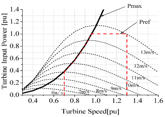
Figure 1.
The wind turbine characteristics.
2.2. DFIG Model and Control
The DFIG grid-connected equivalent circuit [39,40] is shown in Figure 2, with AC-DC-AC power converters linked to the point of common coupling (PCC). The total power ( in Figure 2, is delivered considering the wind speed that is available in the circuitries of the rotor and stator of the wind turbine to the PCC for . Additionally, only the stator active power is supplied via a circuit of the stator to the PCC (), while the active power absorption from the PCC is achieved with the converter [41]. The application of vector control in dq orientation stator frame synchronous axis would result in the 5th order dq representation [42] of the wind generator. The expressions of the components of the voltages of the stator and rotor in dq reference frame considering Figure 2 for the DFIG grid-connected equivalent circuit are:
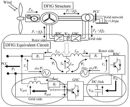
Figure 2.
DFIG grid-connected equivalent circuit.
From Equations (6)–(8), is the direct axis component, is the quadrature component. The stator is the rotor is and is the mutual component. The voltage is the current and the flux vector ψ. The inductance is L and resistance . ), and are the slip, electrical rotor and synchronous speeds, respectively. and are the total inductance in rotor and stator circuits given by and . For the dynamics of the DC-link, the DC power is given as:
From Equation (9), are the DC link capacitor, DC-link voltage and DC-link power. The RSC control of the DFIG wind turbine shown in Figure 3A is regulated by the q and d axis rotor currents and . This is performed by adjusting the active and reactive powers ( of the stator. The MPPT scheme of the wind generator obtains the . The q-axis current regulates rotor speed, while the d-axis current regulates the reactive power. The dq reference voltage components are generated for a Pulse Width Modulator (PWM) signal generator after a dq to abc transformation. The three-phase abc reference voltages are further used for the switching of the IGBTs in the circuitry of the RSC. Thus, the RSC controls the terminal voltage since reactive power is proportional to the voltage. In Figure 3B, the GSC of the wind generator employs a reference frame ac grid to control the DC-link voltage and regulate the reactive power dissipation via the grid side converters connected via the PCC to the grid side network. The Phase Lock Loop (PLL) provides the angle , which is the effective angle used for abc-to-dq and dq-to-abc transformation. The d-axis current (, regulates the DC-link voltage (, while the q-axis current ( regulates the reactive power (. The dq reference voltages are generated and sent to the PMW signal generator after a dq to abc transformation. The generated three-phase reference abc voltages are further used for the switching of the IGBTs of the GSC circuitry.
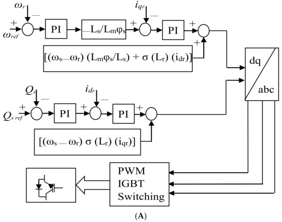
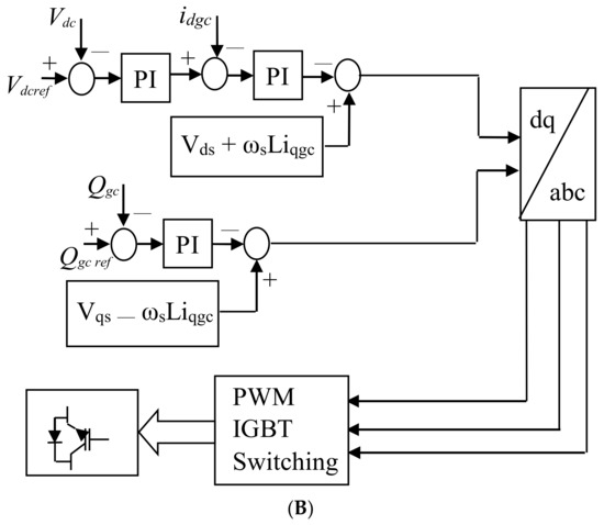
Figure 3.
(A) The DFIG wind turbine RSC control. (B) The DFIG wind turbine GSC control.
2.3. PMSG Model and Control
The PMSG reference power is based on the rated power of the wind generator. In the PMSG, the rated back-to-back converters [43] are connected to the grid, as shown in Figure 4. In order to realize MPPT [44,45], the MSC regulates the speed, while the DC-link voltage stability is achieved by the control of the GSC, in addition to power quality and power factor utilization.
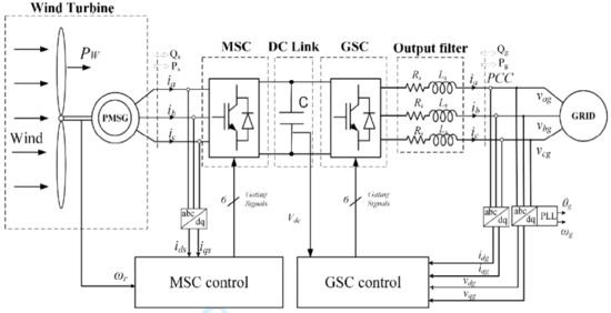
Figure 4.
PMSG wind turbine with back-to-back power converters.
The dq components of the reference model for the PMSG wind turbine for the optimal operation could be expressed as [46]:
Considering Equations (10) and (11),
where the stator d and q voltages are and , the resistance of the stator winding, and are the dq stator currents, the speed of rotation is , the stator flux linkages are and , the leakage inductance of the stator are and , the magnetizing dq inductances are and and the permanent magnet of the flux linkage is . By placing Equations (12) and (13) into (10) and (11), the PMSG dynamics could be expressed by the following differential equations:
The expression for the wind generator’s active and reactive powers are:
By considering the pole pair number, the electrical torque is:
The active and reactive power manipulations of the PMSG wind turbine are performed based on Figure 5. The rotor angle position (θr) that is obtained from the speed of the rotor is used in the effective abc-dq transformation. The active power (Ps) is controlled by the current of the d-axis, while the reactive power (Qs) is based on the current of the q-axis. The reference active power (Pref) of the wind turbine is realized considering the MPPT characteristics. The reference reactive power (Qs*) during operation is usually fixed at 0 value for unity power realization. The power converter PWM switching technique is performed using the obtained three-phase reference voltages (Vsa*, Vsb*, Vsc*) after comparing with a signal generator. These reference voltages are obtained from Vsd* and Vsq* conversion. Figure 6 shows the GSC scheme for the PMSG. The reference dq components are used in regulating the DC-link voltage and reactive power of the wind turbine. The three-phase currents (Iga, Igb, Igc) and voltages (Vga, Vgb, Vgc) are converted using the Park transformation theory into their respective dq rotating references. The network side phase angle (θg) computation is performed using the phase lock loop.
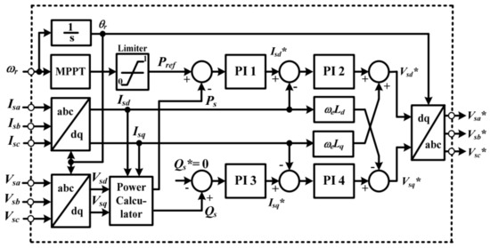
Figure 5.
The machine side converter control of the PMSG.
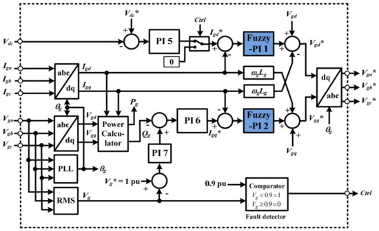
Figure 6.
The grid side converter control of the PMSG.
3. DFIG and PMSG Model Systems with the Fault Current Limiters
The model systems of the DFIG and PMSG wind turbines with the three FCLs are shown in Figure 7 and Figure 8. The parameters of both wind turbines and the FCLs are given in Table 1 and Table 2. The mathematical dynamics of the three FCLs are presented in the subsequent section of this paper.
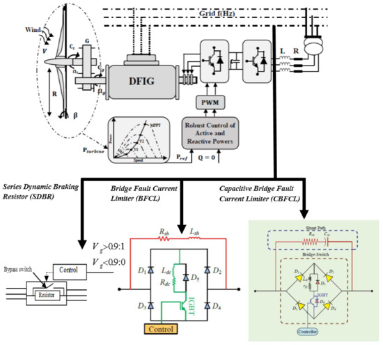
Figure 7.
DFIG wind turbine model with the fault current limiters.
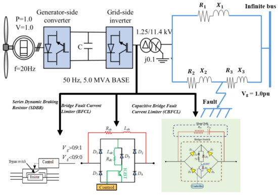
Figure 8.
PMSG wind turbine model with the fault current limiters.

Table 1.
Rating of parameters of the wind turbines.
Table 2.
Parameters of the fault current limiters.
4. Mathematical Dynamics of SDBR in DFIG and PMSG Wind Turbines
4.1. SDBR in DFIG Wind Turbines
The dynamics of the SDBR in DFIG wind turbines are represented in Figure 9. The stator voltage of the DFIG wind turbine during transient conditions [47] is:
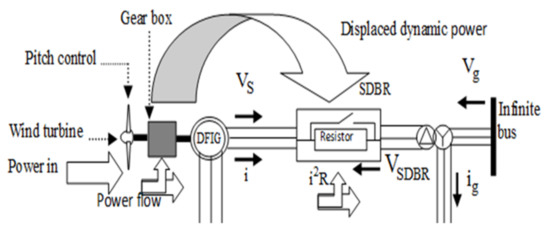
Figure 9.
Dynamics of SDBR in DFIG wind turbines.
are components of the stator’s voltage positive and negative sequences. At normal state, the stator flux is:
With the sudden drop in grid voltage, there are transient components in the stator flux to counteract the transition in the state variables [48]. Therefore, the stator flux would have the natural flux () expressed as:
is the time constant of the stator flux.
During the transient state, the forced flux and the natural flux () in Equation (23) occur, which are the first and second terms. The rotor reference frame is related to the stator flux by
While the rotor induced voltage is
The open-circuit rotor voltage of the DFIG wind turbine is obtained from Equations (23)–(25) as:
Neglecting the term leads to in Equation (26), which gives
During grid fault, the DFIG stator flux comprises a forced component with a high rotor voltage transient and natural flux component. However, there is a decay of the natural flux with time constant of the stator circuit. Consequently, the stator resistance would increase due to the SDBR as below:
The new time constant would now be , making the total current lower, with reduced oscillations during transient state.
4.2. SDBR in PMSG Wind Turbines
The SDBR dynamics in PMSG wind turbines are represented in Figure 10. The power converters of the PMSG are modeled considering the rotating frame of the Park’s transformation. By considering Figure 8, the symmetrical mathematical three-phase voltage source converter model could be expressed as [49]:
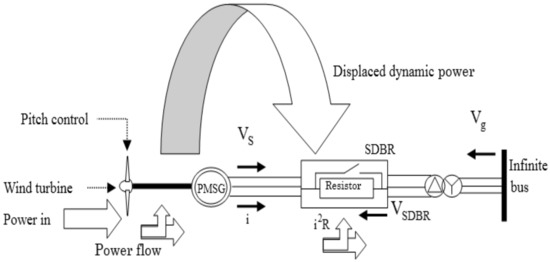
Figure 10.
Dynamics of SDBR in PMSG wind turbines.
From Equations (29)–(32), the dq input currents of the rectifier are and , while the grid dq voltages are ,. The angular frequency is , the dq signals of modulation are and and the vector norm of the signal of modulation is . By using Park’s principle and considering phase-A voltage in line with the reference synchronous dq frame, the dq components of the voltage are:
From Equation (33), the amplitude of the phase voltage of the grid is . Consequently, the active and reactive power computation of the rectifier are:
If then a unity power factor can be achieved. Thus, when better current regulation could be achieved. For and , the voltage source converter could be modeled using the following mathematical expressions for a power factor of 1:
Equation (38) reflects that for the voltage source converter to have a power factor of 1, currents should vary proportionally. Moreover, is used to regulate based on Equations (37) and (39).
Introducing the SDBR in the converter circuitry of the PMSG during the grid fault would influence the DC-link voltage and power flow. From Equations (37)–(39), during steady state, the derivative operating terms would tend to the value of zero. Therefore:
By placing Equation (41) into (42), for a connected load with voltage the command signal is:
Equation (43) would give two solutions as:
The solution for Equation (44) is not admissible, since values are low. Thus, the acceptable solution is Equation (45), with Moreover, the existence of would be possible if:
The condition above is based on the load power consumption. For the effective converter’s operation:
where is the connected DC available maximum power at the PMSG wind turbine converter. From the conservation principle of power, is:
By solving , the DC side maximum power transfer is:
By solving Equations (48) and (49), the DC side maximum power is:
The operation of the PMSG voltage source converter is feasible when
Equation (51) shows the scenario of Equation (47). The maximum input power of the grid, is computed by substituting Equation (50) into Equation (36) for . Thus:
In light of the above analysis and based on Equation (52), the PMSG would experience maximum transfer of power at the grid side during grid fault, and this could be mitigated with the help of the SDBR. Consequently, there is a reduction in the current value, which would lead to reduced oscillations during the grid fault. The SDBR control for both wind turbines is shown in Figure 7 or Figure 8, considering the threshold grid voltage during grid fault.
5. Dynamics of BFCL and CBFL on DFIG and PMSG Wind Turbines
5.1. DFIG and PMSG Wind Turbines with BFCL
The BFCL control is the same as the SDBR control shown in Figure 7 or Figure 8, considering the threshold grid voltage during grid fault. Figure 11 shows the BFCL architecture, where the main bridge circuit has four diodes (D1–D4) and a shunt path has an inductor (Lsh) and resistor (Rsh) in series. The inductor (Ldc) is connected to an IGBT switch. The (Ldc) inductor DC reactor has a current flow in only one direction for positive and negative half cycles of AC. D5 is a free-wheeling diode used for the protection of inductive kick when there is grid disturbance [26]. In steady state, for the positive half cycle, the current flows through the D1-Ldc-Rdc-IGBT-D4 path, and for the negative half cycle, D3-IGBT-Rdc-Ldc-D2. The impedance of the shunt path is very high, so the line current flows through the bridge switch with some negligible leakage currents [50,51].
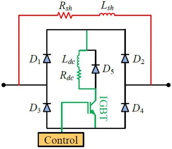
Figure 11.
Control structure of BFCL in DFIG and PMSG wind turbines.
5.2. DFIG and PMSG Wind Turbines with CBFCL
The switching strategy of the CBFCL is the same as the SDBR and BFCL. Figure 12 shows the CBFCL architecture with four diodes, DC reactor (LD) and (rD) switching circuitries and a shunt path with Csh and series resistor Rsh. (D5 and D6) act as fast recovery diodes. The following mathematical dynamics would help understand the behavior of the CBFCL in DFIG and PMSG wind turbines during normal and transient states.
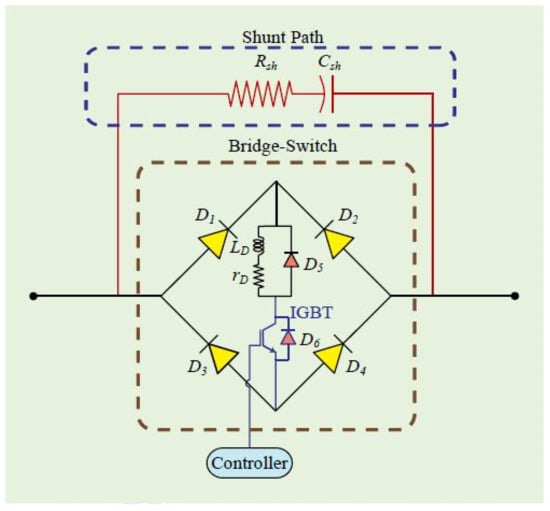
Figure 12.
Control structure of CBFCL in DFIG and PMSG wind turbines.
From Kirchoff’s voltage law, the on-state equations could be derived by applying this law to the equivalent circuit of the bridge in Figure 12, shown in Figure 13. Thus,
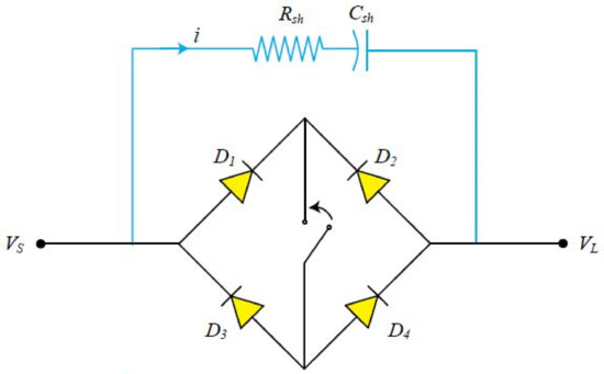
Figure 13.
On-state equivalent CBFCL in DFIG and PMSG wind turbines.
Equation (55) leads to:
From Equations (53)–(56), , and are the capacitor’s voltage, the capacitance of the capacitor, current in the shunt path, resistance of the shunt path, supply voltage and load voltage, respectively. On the other hand, the equations for the off-state are based on applying Kirchoff’s voltage law to the equivalent circuit of the bridge in Figure 12, shown in Figure 14. Thus:
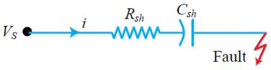
Figure 14.
Off-state equivalent CBFCL in DFIG and PMSG wind turbine.
The current during fault is expressed based on Ohm’s law as:
Simplifying Equation (59) leads to:
6. Results and Discussions
Efforts were made to run simulation studies for both wind generators in order to compare their fault ride-through characteristics using the different FCLs. A three-phase to-ground fault of 100 ms that is severe happened at 10.1 s, and the sequence of the operation of the circuit breakers opening and reclosing at 10.2 s and 11 s, respectively, on the faulted line close to the terminals of the DFIG and PMSG wind turbines, was investigated. The fault performance with and without considering stability augmentation tools of the SDBR, BFCL and CBFCL are presented below in detail.
- A.
- Performance of the DFIG and PMSG wind turbines considering SDBR and BFCL
The DFIG and PMSG wind turbines were subjected to a severe grid fault in the model system, considering no insertion of the SDBR and BFCL and with the insertion of the SDBR and BFCL. Some of the simulation results of the variables of the wind turbines are presented in Figure 15, Figure 16, Figure 17, Figure 18 and Figure 19.
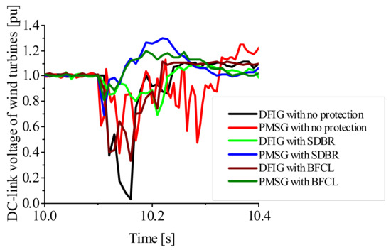
Figure 15.
DC-link voltage of the wind turbines.
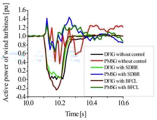
Figure 16.
Active power of the wind turbines.
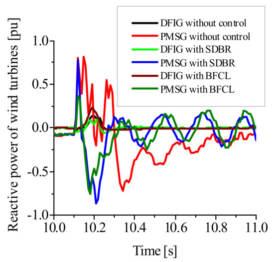
Figure 17.
Reactive power of the wind turbines.
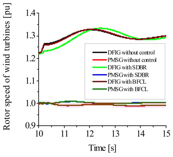
Figure 18.
Rotor speed of the wind turbines.
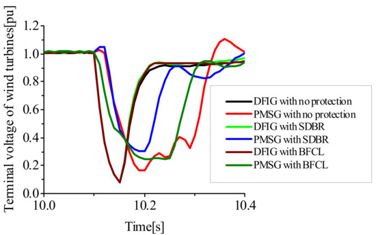
Figure 19.
Terminal voltage of the wind turbines.
From Figure 15, the overshoot experienced by DFIG and PMSG DC-link voltage during grid fault could lead to the damage of the fragile and vulnerable power converters of the wind turbines when no protection control strategy is implemented. While the PMSG wind turbine has more overshoot and slower settling time, the DFIG wind turbine has more DC-link voltage dip, with a faster settling time. Less voltage dip is achieved with the use of the SDBR in the DFIG than when BFCL was used, while the worst-case scenario was when no control was employed. On the other hand, for the PMSG wind turbine, better performance of the DC-link voltage was achieved using the BFCL with less overshoot than when the SDBR was employed. The same analogy goes for the active power variable in Figure 16, with the SDBR performing better in the DFIG wind turbine while the BFCL for the PMSG wind turbine. The responses for the reactive power and rotor speed are shown in Figure 17 and Figure 18. The reactive power of the wind turbines was effectively controlled using the SDBR and BFCL, while there was the minimal influence of the FCLs on the rotor speed of the wind turbines. The influence of the FCLs is more obvious in the terminal voltage response of the PMSG shown in Figure 19 during the grid fault than in the DFIG. When no control was implemented in both wind turbines, more overshoot and less settling time were observed in the variable of the terminal voltage. However, the SDBR gave a quicker recovery of the terminal voltage variable than the BFCL. Based on the above analysis, the effect of the FCLs is more obvious for the PMSG than the DFIG because the PMSG-based wind turbine is decoupled fully from the power grid due to its back-to-back power converter. Consequently, the operation of the wind turbines is a critical situation during faulty conditions, when no FCL is implemented. In light of this, the subsequent sections of this paper consider the investigation of the CBFCL on the two wind turbines separately in order to know its impact compared to the SDBR and the BFCL topologies.
- B.
- Performance of the DFIG wind turbine considering SDBR, BFCL and CBFCL
The performance of the DFIG was further investigated considering the CBFCL in addition to those obtained using the SDBR and BFCL. Some of the simulation results are presented in Figure 20, Figure 21, Figure 22 and Figure 23. In Figure 20, the SDBR outperforms the BFCL and the CBFCL, with improved undershoot, overshoot and faster settling time. However, more reactive power was dissipated by the use of the BFCL and the CBFCL in the grid side converter of the DFIG wind turbine, as shown in Figure 21. The effect of the FCLs on the terminal voltage is shown in Figure 22 and Figure 23. In Figure 22 and Figure 23, when no FCL scheme was considered, the terminal voltage recovered slowly; however, with the use of the SDBR, the voltage recovery was faster than the use of the BFCL and CBFCL control strategies. Some of the reasons for the improved performance of the SDBR over the BFCL and the CBFCL are that the SDBR has more capability to respond faster during the grid fault by reducing the high current flow, at the same time, ensuring no overvoltage is induced, thus, leading to no power converter control loss.
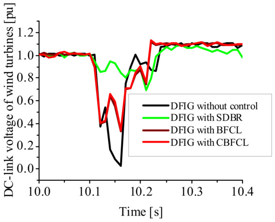
Figure 20.
DC-link voltage of DFIG wind turbine.
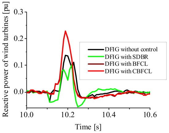
Figure 21.
Reactive power of DFIG wind turbine.
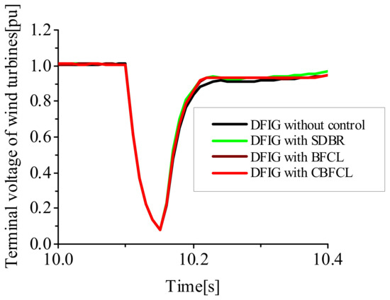
Figure 22.
Terminal voltage of DFIG wind turbine.
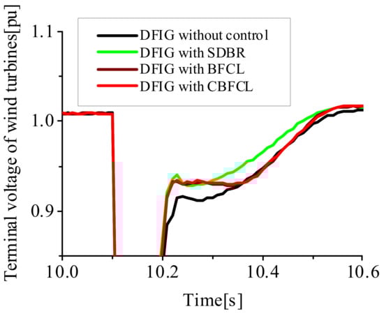
Figure 23.
Terminal voltage of DFIG wind turbine (zoomed).
- C.
- Performance of the PMSG wind turbine considering SDBR, BFCL and CBFCL
The performance of the PMSG wind turbine was also investigated in this section considering the CBFCL, in addition to those obtained using the SDBR and BFCL. Some of the simulation results are presented in Figure 24, Figure 25 and Figure 26 during the grid fault. In Figure 24 and Figure 25, the CBFCL performed better than the SDBR and BFCL schemes, with improved undershoot, overshoot and faster settling time. However, the SDBR scheme performed better than the BFCL and the CBFCL schemes in the recovery of the terminal voltage, with a faster settling time and voltage dip. Some of the reasons for the improved performance of the SDBR scheme in the voltage variable of the PMSG were the same as given for the DFIG wind turbine. Apart from the voltage variable of the PMSG wind turbine, the performance of the CBFCL was better in other variables of the PMSG wind turbine during grid fault.
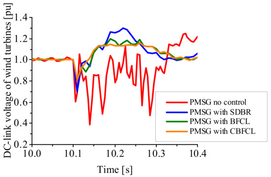
Figure 24.
DC-link voltage of PMSG wind turbine.
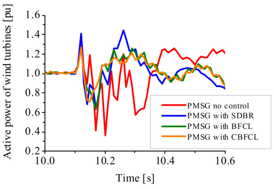
Figure 25.
Active power of PMSG wind turbine.
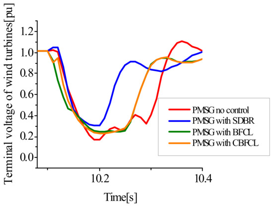
Figure 26.
Terminal voltage of PMSG wind turbine.
Table 3 and Table 4 show the numerical index performance of both wind turbines and the various FCLs employed in this study.
Table 3.
Numerical Index Performance of the Wind Turbines.
Table 4.
Numerical Index Performance of the Wind Turbines considering CBFCL.
7. Conclusions
This paper presented a comparative analysis of the augmentation performance of DFIG and PMSG wind turbines with the same machine ratings during grid fault, considering different Fault Current Limiters (FCLs). The considered FCLs were the Series Dynamic Braking Resistor (SDBR), Bridge Fault Current Limiter (BFCL) and the Capacitive Bridge Fault Current Limiter (CBFCL). The wind turbines were operated under the same conditions. Both wind turbines were affected by the connection of the FCLs in their stator circuits during severe grid disturbance. However, the influence of the FCLs was more observed in the PMSG wind turbine compared to the DFIG wind turbine. This is due to the fact that the PMSG wind turbine technology enables the decoupling of its full back-to-back power converters at the power grid. When no control strategy of FCLs was implemented in the wind turbines, a critical situation of operation during faulty conditions would result, making the DC-link voltage dip to almost 0.0 pu, with an overshoot of over 10%, and a high settling time of over 0.4 s for the DFIG, while for the PMSG, an overshoot of 30%, DC-link voltage of 0.4 pu and over 0.5 s of settling time were observed. The performance of the DFIG wind turbine was better using the SDBR than the use of BFCL and CBFCL control schemes, with improved numerical index performance of 8% overshoot, 0.7 pu dip and 0.3 s for the DFIG. On the other hand, the performance of the PMSG wind turbine was better using the CBFCL with 9% overshoot, 0.8 pu dip and 0.35 s settling time for the DC-link voltage. Moreover, a faster settling time was also observed using the FCLs for both wind turbines. The performance of the PMSG variables was better using the CBFCL than the SDBR and the BFCL control strategies, except for the terminal grid voltage variable. Therefore, it is recommended to use the FCLs with DFIG- or PMSG-based variable speed wind turbines to obtain superior fault ride-through performance based on the intended purpose.
Funding
This research received no external funding.
Institutional Review Board Statement
Not applicable.
Informed Consent Statement
Not applicable.
Data Availability Statement
Not applicable.
Conflicts of Interest
The authors declare no conflict of interest.
Abbreviations
| List of symbols | |
| reactance, | |
| resistance, | |
| impedance, | |
| torque, N | |
| air density, | |
| R | radius, m |
| wind speed, | |
| Power coefficient | |
| is the ratio of the tip speed | |
| is the turbine coefficient | |
| is the stator power, Watt | |
| is the rotor power, Watt | |
| quadrature axis rotor current, A direct axis rotor current, A | |
| stator reactive power, VA | |
| stator inductance, H | |
| magnetizing inductance, H | |
| rotor inductance, H | |
| stator flux, T | |
| stator angular frequency, Hz | |
| rotor angular frequency, Hz | |
| rotor leakage factor | |
| , | stationary frames |
| r | s FIG rotor and stator quantities |
| g | DFIG grid-side converter circuit quantity |
| L | inductance, H |
| R | resistance, |
| dc-link voltage, V | |
| reference power of turbine, W | |
| θr | rotor angle position |
| Isd, Isq | direct and quadrature stator current, A |
| Vsa*, Vsb*, Vsc* | reference abc stator voltages, V |
| Vsd* and Vsq* | reference dq stator voltages, V |
| Iga, Igb, Igc | abc grid currents, A |
| Vga, Vgb, Vgc | abc grid voltages, V |
| components of the stator’s voltage positive and negative sequences, V | |
| time constant of the stator flux, S | |
| natural flux, T | |
| rotor induced voltage | |
| , | dq current input of the rectifier’s axes, A |
| , | dq voltage of the grid voltage axes components, V |
| angular frequency voltage, Hz | |
| modulating signal of the rectifier’s d and q axes components | |
| modulation signal vector norm | |
| phase grid voltage amplitude, | |
| resistance of the series dynamic braking resistor, | |
| resistance of the load, | |
| available power at the DC, W | |
| maximal available power at the DC, W |
References
- Wind-Fuels and Technologies, International Energy Agency. 2021. Available online: https://www.iea.org (accessed on 21 May 2022).
- Nduwamungu, A.; Ntagwirumugara, E.; Mulolani, F.; Bashir, W. Fault Ride through Capability Analysis (FRT) in Wind Power Plants with Doubly Fed Induction Generators for Smart Grid Technologies. Energies 2020, 13, 4260. [Google Scholar] [CrossRef]
- Sitharthan, R.; Karthikeyan, M.; Sundar, D.S.; Rajasekaran, S. Adaptive hybrid intelligent MPPT controller to approximate effectual wind speed and optimal rotor speed of variable speed wind turbine. ISA Trans. 2020, 96, 479–489. [Google Scholar] [CrossRef] [PubMed]
- Okedu, K.E.; Muyeen, S.M.; Takahashi, R.; Tamura, J. Protection schemes for DFIG considering rotor current and DC-link voltage. In Proceedings of the 24th IEEE-ICEMS International Conference on Electrical Machines and System, Beijing, China, 20–23 August 2011; pp. 1–6. [Google Scholar]
- Ouyang, J.; Tang, T.; Yao, J.; Li, M. Active Voltage Control for DFIG-Based Wind Farm Integrated Power System by Coordinating Active and Reactive Powers under Wind Speed Variations. IEEE Trans. Energy Convers. 2019, 34, 1504–1511. [Google Scholar] [CrossRef]
- Okedu, K.E. Introductory Chapter of the book Power System Stability; INTECH: Horwich, UK, 2019; pp. 1–10. [Google Scholar]
- Shao, H.; Li, Z.; Zhou, D.; Sun, S.; Guo, L.; Rao, F. Stability Enhancement and Direct Speed Control of DFIG Inertia Emulation Control Strategy. IEEE Access 2019, 7, 120089–120105. [Google Scholar] [CrossRef]
- He, X.; Fang, X.; Yu, J. Distributed Energy Management Strategy for Reaching Cost-Driven Optimal Operation Integrated with Wind Forecasting in Multimicrogrids System. IEEE Trans. Syst. Man Cyber. Syst. 2019, 49, 1643–1651. [Google Scholar] [CrossRef]
- Qazi, H.W.; Wall, P.; Escudero, M.V.; Carville, C.; Cunniffe, N.; Sullivan, J.O. Impacts of Fault Ride Through Behavior of Wind Farms on a Low Inertia System. IEEE Trans. Power Syst. 2020, 28, 1. [Google Scholar] [CrossRef]
- Chunli, L.; Zefu, T.; Huang, Q.; Nie, W.; Yao, J. Lifetime Evaluation of IGBT Module in DFIG Considering Wind Turbulence and Nonlinear Damage Accumulation Effect. In Proceedings of the 2019 IEEE 2nd International Conference on Automation, Electronics and Electrical Engineering (AUTEEE), Shenyang, China, 22–24 November 2019. [Google Scholar]
- Okedu, K.E.; Muyeen, S.M.; Takahashi, R.; Tamura, J. Use of Supplementary Rotor Current Control in DFIG to Augment Fault Ride Through of Wind Farm as per Grid Requirement. In Proceedings of the 37th Annual Conference of IEEE Industrial Electronics Society (IECON 2011), Melbourne, Australia, 7–10 November 2011. [Google Scholar]
- Okedu, K.E.; Muyeen, S.M.; Takahashi, R.; Tamura, J. Improvement of Fault Ride Through Capability of Wind Farm using DFIG Considering SDBR. In Proceedings of the14th European Conference of Power Electronics EPE, Birmingham, UK, 30 August–1 September 2011; pp. 1–10. [Google Scholar]
- Okedu, K.E. Enhancing DFIG Wind Turbine during Three-phase Fault Using Parallel Interleaved Converters and Dynamic Resistor. IET Renew. Power Gener. 2016, 10, 1211–1219. [Google Scholar] [CrossRef]
- Okedu, K.E.; Muyeen, S.M.; Takahashi, R.; Tamura, J. Participation of FACTS in Stabilizing DFIG with Crowbar during Grid Fault Based on Grid Codes. In Proceedings of the 6th IEEE-GCC Conference and Exhibition, Dubai, UAE, 19–22 February 2011; pp. 365–368. [Google Scholar]
- Boujoudi, B.; Kheddioui, E.; Machkour, N.; Achalhi, A.; Bezza, M. Comparative study between different types of control of the wind turbine in case of voltage dips. In Proceedings of the 2018 Renewable Energies, Power Systems & Green Inclusive Economy (REPS-GIE), Casablanca, Morocco, 23–24 April 2018; pp. 1–5. [Google Scholar]
- Okedu, K.E.; Muyeen, S.M.; Takahashi, R.; Tamura, J. Comparative Study between Two Protection Schemes for DFIG-based Wind Generator. In Proceedings of the 23rd IEEE-ICEMS (International Conference on Electrical Machines and Systems), Seoul, Korea, 10–13 October 2010; pp. 62–67. [Google Scholar]
- Okedu, K.E.; Muyeen, S.M.; Takahashi, R.; Tamura, J. Stabilization of wind farms by DFIG-based variable speed wind generators. In Proceedings of the International Conference of Electrical Machines and Systems (ICEMS), Seoul, Korea, 10–13 October 2010; pp. 464–469. [Google Scholar]
- Bekakra, Y.; Attous, D.B. Sliding Mode Controls of Active and Reactive Power of a DFIG with MPPT for Variable Speed Wind Energy Conversion. Aust. J. Basic. Appl. Sci. 2011, 5, 2274–2286. [Google Scholar]
- Ali, D.M.; Jemli, K.; Jemli, M.; Gossa, M. Doubly Fed Induction Generator, with Crowbar System under Micro-Interruptions Fault. Int. J. Electr. Eng. Inform. 2010, 2, 216–231. [Google Scholar]
- Suthar, D.B. Wind Energy Integration for DFIG Based Wind Turbine Fault Ride Through. Indian J. Appl. Res. 2014, 4, 216–220. [Google Scholar] [CrossRef]
- Lamchich, M.T.; Lachguer, N. Matlab, Simulink as Simulation Tool for Wind Generation Systems Based on Doubly Fed Induction Machines. In MATLAB—A Fundamental Tool for Scientific Computing and Engineering Applications; Chapter 7; INTECH Publishing: Horwich, UK, 2012; Volume 2, pp. 139–160. [Google Scholar]
- Noubrik, A.; Chrifi-Alaoui, L.; Bussy, P.; Benchaib, A. Analysis and Simulation of a 1.5MVA Doubly Fed Wind Power in Matlab Sim PowerSystems using Crowbar during Power Systems Disturbances. In Proceedings of the IEEE-2011 International Conference on Communications, Computing and Control Applications (CCCA), Hammamet, Tunisia, 3–5 March 2011. [Google Scholar]
- Nasiri, M.; Mohammadi, R. Peak current limitation for grid-side inverter by limited active power in PMSG-based wind turbines during different grid faults. IEEE Trans. Sustain. Energy 2017, 8, 3–12. [Google Scholar] [CrossRef]
- Gencer, A. Analysis and control of fault ride through capability improvement PMSG based on WECS using active crowbar system during different fault conditions. Elektron. Elektrotech 2018, 24, 64–69. [Google Scholar] [CrossRef] [Green Version]
- Yehia, D.M.; Mansour, D.A.; Yuan, W. Fault ride-through enhancement of PMSG wind turbines with DC microgrids using resistive-type SFCL. IEEE Trans. Appl. Supercond. 2018, 28, 1–5. [Google Scholar] [CrossRef]
- Islam, R.; Huda, N.; Hasan, J.; Sadi, M.A.H.; AbuHussein, A.; Roy, T.K.; Mahmud, A. Fault ride through capability improvement of dfig based wind farm using nonlinear controller based bridge-type flux coupling non-superconducting fault current limiter. Energies 2020, 13, 1696. [Google Scholar] [CrossRef] [Green Version]
- Firouzi, M. Low-voltage ride-through (lvrt) capability enhancement of dfig-based wind farm by using bridge-type superconducting fault current limiter (btsfcl). J. Power Technol. 2020, 99, 245–253. [Google Scholar]
- Islam, M.R.; Hasan, J.; Hasan, M.M.; Huda, M.N.; Sadi, M.A.H. AbuHussein, Performance improvement of dfig-based wind farms using narma-l2 controlled bridge-type flux coupling non-superconducting fault current limiter. IET Gener. Transm. Distrib. 2021, 14, 6580–6593. [Google Scholar] [CrossRef]
- Hasan, J.; Islam, M.R.; Islam, M.R.; Kouzani, A.Z.; Mahmud, M.P. A capacitive bridge-type superconducting fault current limiter to improve the transient performance of dfig/pv/sg-based hybrid power system. IEEE Trans. Appl. Supercond. 2021, 31, 1–5. [Google Scholar] [CrossRef]
- Rashid, G.; Ali, M.H. A modified bridge-type fault current limiter for fault ride-through capacity enhancement of fixed speed wind generator. IEEE Trans. Energy Convers. 2014, 29, 527–534. [Google Scholar]
- Moghimian, M.M.; Radmehr, M.; Firouzi, M. Series resonance fault current limiter (SRFCL) with mov for lvrt enhancement in dfig-based wind farms. Electr. Power Compon. Syst. 2019, 47, 1814–1825. [Google Scholar] [CrossRef]
- Yang, J.; Fletcher, J.E.; O’Reilly, J. A series-dynamic-resistor-based converter protection scheme for doubly-fed induction generator during various fault conditions. IEEE Trans. Energy Convers. 2010, 25, 422–432. [Google Scholar] [CrossRef] [Green Version]
- Din, Z.; Zhang, J.; Xu, Z.; Zhang, Y.; Zhao, J. Low voltage and high voltage ride-through technologies for doubly fed induction generator system: Comprehensive review and future trends. IET Renew. Power Gener. 2021, 15, 614–630. [Google Scholar] [CrossRef]
- Firouzi, M.; Gharehpetian, G. Improving fault ride-through capability of fixed-speed wind turbine by using bridge-type fault current limiter. IEEE Trans. Energy Convers. 2013, 28, 361–369. [Google Scholar] [CrossRef]
- Naderi, S.B.; Jafari, M.; Hagh, M.T. Parallel-resonance-type fault current limiter. IEEE Trans. Ind. Electron. 2012, 60, 2538–2546. [Google Scholar] [CrossRef] [Green Version]
- PSCAD/EMTDC Manual; Version 4.6.0; Manitoba HVDC Lab.: Winnipeg, MB, Canada, 2016.
- Garcia-Garcia, M.; Comech, M.P.; Sallan, J.; Liombart, A. Modelling Wind Farms for Grid Disturbances Studies. Sci. Direct Renew. Energy 2008, 33, 2019–2121. [Google Scholar]
- Okedu, K.E.; Muyeen, S.M.; Takahashi, R.; Tamura, J. Application of SDBR with DFIG to Augment Wind Farm Fault Ride Through. In Proceedings of the 24th IEEE-ICEMS (International Conference on Electrical Machines and Systems), Beijing, China, 20–23 August 2011; pp. 1–6. [Google Scholar]
- Okedu, K.E. Enhancing the performance of DFIG variable speed wind turbine using parallel integrated capacitor and modified modulated braking resistor. IET Gener. Transm. Distrib. 2019, 13, 3378–3387. [Google Scholar] [CrossRef]
- Okedu, K.E. Improving the transient performance of DFIG wind turbine using pitch angle controller low pass filter timing and network side connected damper circuitry. IET Renew. Power Gener. 2020, 14, 1219–1227. [Google Scholar] [CrossRef]
- Zubia, I.; Ostolaza, J.X.; Susperrgui, A.; Ugartemendia, J.J. Multi-machine transient modeling of wind farms, an essential approach to the study of fault conditions in the distribution network. Appl. Energy 2012, 89, 421–429. [Google Scholar] [CrossRef]
- Kong, X.; Xianggen, Z.Z.; Wen, M. Study of fault current characteristics of the DFIG considering dynamic response of the RSC. IEEE Trans. Energy Convers. 2014, 2, 278–287. [Google Scholar] [CrossRef]
- Li, Y.; Xu, Z.; Wong, K.P. Advanced control strategies of PMSG-based wind turbines for system inertia support. IEEE Trans. Power Syst. 2017, 32, 3027–3037. [Google Scholar] [CrossRef]
- Priyadarshi, N.; Ramachandaramurthy, V.; Padmanaban, S.; Azam, F. An ant colony optimized MPPT for standalone hybrid PV-wind power system with single Cuk converter. Energies 2019, 12, 167. [Google Scholar] [CrossRef] [Green Version]
- Lee, S.W.; Chun, K.H. Adaptive sliding mode control for PMSG wind turbine systems. Energies 2019, 12, 595. [Google Scholar] [CrossRef] [Green Version]
- Li, S.; Haskew, T.A.; Xu, L. Conventional and novel control design for direct driven PMSG wind turbines. Electr. Power Syst. Res. 2010, 80, 328–338. [Google Scholar] [CrossRef]
- Yang, D.; Ruan, X.; Wu, H. Impedance shaping of the grid-connected inverter with LCL filter to improve its adaptability to the weak grid condition. IEEE Trans. Power Electron. 2014, 29, 5795–5805. [Google Scholar] [CrossRef]
- Thierry, C.V. Voltage Stability of Electric Power Systems; Springer: Berlin/Heidelberg, Germany, 1998. [Google Scholar]
- Grunau, S.; Fuchs, W.F. Effect of Wind-Energy Power Injection into Weak Grids; Institute for Power Electronics and Electrical Drives, Christian-Albrechts-University of Kiel D-24143 Kiel: Kiel, Germany, 2012; pp. 1–7. [Google Scholar]
- Rashid, G.; Ali, M.H. Fault ride through capability improvement of DFIG based wind farm by fuzzy logic controlled parallel resonance fault current limiter. Electr. Power Syst. Res. 2017, 146, 1–8. [Google Scholar] [CrossRef]
- Rashid, G.; Ali, M.H. Nonlinear control-based modified BFCL for LVRT capacity enhancement of DFIG-based wind farm. IEEE Trans. Energy Convers. 2016, 32, 284–295. [Google Scholar] [CrossRef]
Publisher’s Note: MDPI stays neutral with regard to jurisdictional claims in published maps and institutional affiliations. |
© 2022 by the author. Licensee MDPI, Basel, Switzerland. This article is an open access article distributed under the terms and conditions of the Creative Commons Attribution (CC BY) license (https://creativecommons.org/licenses/by/4.0/).