Abstract
In this paper a general-purpose procedure for optimizing a resonant inductive wireless power transfer link adopting a multiple-input-multiple-output (MIMO) configuration is presented. The wireless link is described in a general–purpose way as a multi-port electrical network that can be the result of either analytical calculations, full–wave simulations, or measurements. An eigenvalue problem is then derived to determine the link optimal impedance terminations for efficiency maximization. A step-by-step procedure is proposed to solve the eigenvalue problem using a computer algebra system, it provides the configuration of the link, optimal sources, and loads for maximizing the efficiency. The main advantage of the proposed approach is that it is general: it is valid for any strictly–passive multi–port network and is therefore applicable to any wireless power transfer (WPT) link. To validate the presented theory, an example of application is illustrated for a link using three transmitters and two receivers whose impedance matrix was derived from full-wave simulations.
1. Introduction
Resonant inductive wireless power transfer (WPT) is an attractive and efficient way for recharging electronic devices [1,2,3,4]. The simplest implementation consists of just two magnetically coupled resonators in a single-input-single-output (SISO) configuration where power is wirelessly transferred from a single transmitter to a single receiver. This configuration has been widely investigated in the literature and the design equations for maximizing the possible figures of merit of interest have been derived [5,6,7,8,9]. In the SISO configuration, a possible strategy for improving the performance in terms of either transfer distance or efficiency consists in using additional resonators interposed between the transmitter and the receiver [10,11,12].
One of the main limitation of SISO resonant inductive WPT is the strong dependence of the performance on the correct alignment between the transmitting and the receiving coils. As a result, even a small displacement of the receiving coil with respect to the transmitting coil can lead to a consistent deterioration of the performance. This problem could be alleviated by using multiple transmitters thus resulting in a multiple-input-single-output (MISO) configuration [13,14,15,16,17]. In these configurations the number and the positions of the transmitters can be optimized so to achieve a nearly constant performance for a receiver positioned in a given volume [14].
In [15] the solution for maximizing the efficiency has been formulated as a convex optimization problem. In [16] the use of a linear array of transmitters, activated two at a time, is suggested for providing a constant output voltage to a load moving along a linear path. In [17] the case of a link using two transmitters has been considered. In more detail, in [17] the optimal load for both the maximum power and the maximum efficiency solutions have been presented.
Another configuration of interest is that using a single transmitter and multiple receivers (SIMO) that allows us to recharge multiple devices by using a single transmitter [18,19,20,21,22,23].
In [20], the case of a two-receiver system is considered and the optimal loads are derived for the case of uncoupled receivers. The case of possibly coupled receivers is considered in [21,22,23]. In particular, the maximum power transfer theorem for an N-port is used in [21] for deriving the expressions of the optimal loads. In [22] a time-division multiplexing is used to maximize the system efficiency.
The case of a multiple-input-multiple-output (MIMO) configuration has been analyzed in [24], where the optimal loads are calculated by imposing the first-order necessary condition consisting in imposing the zeroing of the first-order partial derivatives of the efficiency with respect to the input and output currents. However, the results reported in [24] are derived assuming that all the couplings among the transmitters and the receivers are purely inductive; this being equivalent to assume that the conductivity of the propagation channel is negligibly small.
This limitation has overcome in [25,26], where the solution for maximizing the efficiency is derived from a generalized eigenvalue problem. In [25] the case of a resonant inductive WPT link in SIMO configuration is solved. In [26] the general solving equation is derived for a generic multi-port network representative of a generic WPT link. The same approach is adopted in this paper, where the analysis presented in [26] is specialized and validated for the case of a resonant inductive WPT link in MIMO configuration.
It is demonstrated that for a strictly passive reciprocal MIMO network the expressions of the optimal loads maximizing the efficiency can be derived from a generalized eigenvalue problem. It is shown that the desired solution can be obtained by simple manipulation of the impedance matrix of the network. Accordingly, in order to solve the problem of efficiency maximization one just needs the impedance matrix of the link that can be the result of measurements, simulations or theoretical analysis. A validation of the theory for the case of a link using three transmitters and two receivers is presented.
The paper is organized as follows. In Section 2 the solution of efficiency maximization, identified with the power gain of the link, is presented for the general case of a strictly passive reciprocal -port network. In Section 3 the solution is specialized for the case of a MIMO resonant inductive WPT link. In Section 4 the special cases of MISO and SIMO configurations are considered and discussed. The derived analytical formulas are validated in Section 5 and some conclusions are drawn in Section 6.
2. Power Gain Maximization for a Lossy Reciprocal Multiport Network
In this section the general case of a strictly passive reciprocal -port network is considered and the problem of power transfer efficiency maximization is analyzed. It is shown that the problem of finding the optimal terminating impedances can be formulated as a generalized eigenvalue problem.
2.1. Statement of the Problem
The analyzed problem is illustrated in Figure 1, a strictly passive reciprocal multiport network , operating in sinusoidal steady-state, whose ports are divided into two sets of M and N ports is considered. In the following the two sets will be referred as the set and the set , and their ports will be denoted by the indexes and . The network is described in terms of an impedance matrix .
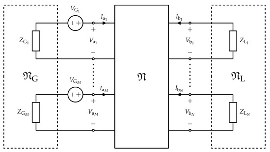
Figure 1.
Schematic representation of a multiple-input-multiple-output (MIMO) wireless power transfer (WPT) link.
It is assumed that the set of M ports is connected to an M-port power source, represented by the equivalent Thévenin circuit depicted in Figure 1, which consists of an M-port network , described by an impedance matrix , and of a set of M sinusoidal generators. The M-vector of the generator voltage phasors will be indicated as . In many practical cases, the source may consist of a set of uncoupled generators. In these cases, the matrix is diagonal, i.e. , with .
It is also assumed that the set of is connected to a load network , described by an impedance matrix . In practical cases, may consist of N independent load impedances, hence , with . According to the impedance matrix representation of the network, it is possible to write:
It is convenient to partition, with respect to M and N, the vectors and of voltage and current phasors at the ports of and, accordingly, the matrix as
where denotes the transpose. The subscript indicates the M-subvectors and the submatrices corresponding to the ports of set . Similarly the subscript indicates the N-subvectors and the submatrices corresponding to the ports of set . Finally, the subscript is used to denote the transfer-impedance submatrix relating the voltages at the ports of set to the currents at the ports of set .
The problem of determining the impedances and and the source voltages which realize the maximum power transfer at the input and the output ports of simultaneously is then considered.
It can be shown [27] that, in the case of multiport networks, the impedances providing the maximum power transfer are not univocally defined, but there is a unique set of port currents corresponding to the maximum power transfer operation. Hence it is convenient to state the problem in terms of currents, and to seek for the currents and for which the maximum power transfer between the two sets of ports is achieved.
Making use of (2), the average powers entering the network at the two sets of ports can be expressed as
and
where denotes the conjugate, and the conjugate transpose. The previous equations can be cast in the form
where the matrices and are defined as
and
Since is assumed to be reciprocal and strictly passive, is symmetric and, for any nonzero vector , the total average power entering satisfies the condition
Hence , and, consequently, and are positive definite symmetric real matrices. It can also be noted that it results
From (6) and (7) it can be recognized that, for , is singular and is nonsingular if and only if has full rank. Similarly, for , is singular and is nonsingular if and only if has full rank. Finally, for both and are nonsingular if and only if is nonsingular.
If the network is operated as shown in Figure 1, i.e., the power supply is provided at ports , the input power is and the power delivered to the load is . Hence, the network power gain can be expressed as
It is noted that has the form of a generalized Rayleigh quotient. Its maximum can be thus determined by solving a generalized eigenvalue problem. As a matter of fact, using the quotient rule and taking into account that and are Hermitian matrices, the differential of can be calculated as
Hence, requiring yields
which can be recognized as a generalized eigenvalue problem with being the eigenvalue and the corresponding eigenvector.
In the given hypotheses, the maximum power gain, and the corresponding currents (up to an arbitrary factor) can be determined by solving (12) with the constraint
In fact, since for it results
condition (13) implies
which confirms that power transfer occurs from ports to ports .
If and are the maximum eigenvalue and the associate eigenvector satisfying (13), the maximum power gain, , and the corresponding port currents, , are
and
It can be observed that by (12) it is also possible to determine the maximum power gain when the role of the ports is interchanged, that is when the power supply is provided at ports . In this case the power gain is , the corresponding currents are still given by , and the solution must satisfy the constraint
which, according to (14), provides and, consequently, . In this case the optimal gain corresponds to the minimum satisfying (18).
It can be demonstrated that if is a finite nonzero eigenvalue of (12), then also is an eigenvalue. A proof is provided in Appendix A. It will also be shown that the maximum power gain has the same value in both directions: .
2.2. Solving the Generalized Eigenvalue Problem
It can be noted that both and are independent of and . As a consequence, the maximum of and the corresponding port currents do not depend on the reactive couplings among the ports of set and among the ports of set .
When or is nonsingular, it is possible to convert (12) into an ordinary eigenvalue problem by multiplying both sides by or , however, this transformation can not be applied in the general case. Nevertheless, it is always possible to transform (12) into an equivalent problem involving a positive definite matrix by adding to both sides
Since, as it was previously shown, is positive definite, (21) can be always transformed into an ordinary Hermitian eigenvalue problem. In fact, by introducing the Cholesky decomposition of ,
where is a lower triangular real matrix, (21) can be rewritten as
This allows us to state that all the eigenvalues of (21) and, consequently, all the eigenvalues of (12) are real. Moreover, according to the Courant–Fischer–Weyl min–max theorem, the minimum and maximum eigenvalue of (21) correspond to the absolute minimum and the absolute maximum of the function
for .
Since, for , is a monotonic increasing function of with values ranging in the interval , if the minimum eigenvalue satisfies the condition , the maximum power transfer efficiency from to is given by
and the eigenvector associated to represents (up to an arbitrary scale factor) the port currents in maximum efficiency operation.
In a similar way it is possible to show that the power transfer efficiency from to , has a maximum if the maximum eigenvalue satisfies the condition , and in this case it results
2.3. Calculation of the Optimal Terminating Networks and
After computing the optimal currents (17) the corresponding port voltages
can be derived by (2), then the optimal terminations for the network can be readily determined as follows.
On the source side, the impedance matrix of and the generator voltages are subject to the constraint
In addition, since the M-port source is supposed to operate in maximum power transfer conditions, must coincide with its optimal current, which requires [27]
For , the values of and , which satisfy these conditions, are not unique. In fact, by combining (29) and (30), the result is that any matrix such that
represents an acceptable solution. In particular it can be noted that it is possible to realize as a set of M independent passive impedances, provided that the possible zero elements of correspond to zero elements of , and that the phase difference between any two corresponding elements of and is in absolute value. In this case it is possible to set
On the output side, the impedance matrix of is only subject to the constraint
hence, also in this case, the solution is not unique. In particular, the diagonal solution
can be realized with passive impedance if the possible zero elements of correspond to zero elements of , and the phase difference between voltages and currents at each port is in absolute value.
3. The Case of a Resonant Inductive WPT Link
The WPT link illustrated in Figure 2 is considered. It is assumed that the WPT link is realized by two sets of coupled inductors, and . Each inductor is compensated by a series capacitor realizing the resonance condition at the angular frequency : and .
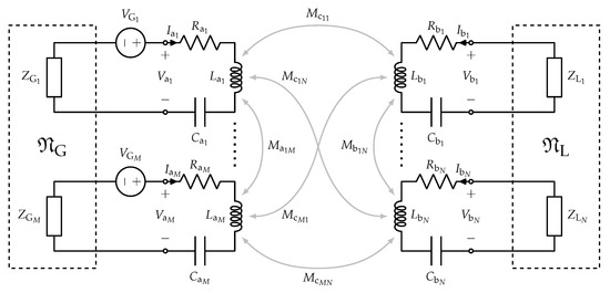
Figure 2.
Resonant inductive MIMO WPT link.
It is also assumed that the WPT link is driven by a set of M sinusoidal generators with angular frequency . In the following the two sets of inductors will also be referred as the transmitting coils and the receiving coils, respectively.
The inductor losses are represented by the series resistances and . The mutual inductance between the inductors and , with and is indicated by . Similarly, the mutual inductance between the inductors and , with and is indicated by . Finally, the mutual inductance between the inductors and , with and is indicated by .
It is convenient to introduce the inductor quality factors
and the coupling coefficients, defined as
The coupling coefficients are such that their absolute value is in the range with a positive or negative sign depending on the sign of the induced voltage (i.e., a generic coupling coefficient between a coil i and a coil j is positive if a positive current in coil i induces a positive voltage in coil j, otherwise it is negative). It is also convenient to normalize the impedance matrix, , of the -port network formed by the coupled inductors with respect to the inductor reactances. By introducing the normalization matrix
where
the normalized impedance matrix, , is thus computed as
and the expressions of the submatrices of are found to be
As a consequence, the eigenvalue problem (12), and the equivalent one expressed in (21), can be also stated in terms of normalized matrices as
where, making use of (6) and (7), the expressions of the matrices , , , and , can be derived as
and
It can be noted that the matrices , , and, consequently, the maximum gain and the optimal currents are only determined by the inductor quality factors and by the coupling coefficients between the transmitting and the receiving coils, while they are independent of the couplings between the transmitters and between the receivers. This means that a possible coupling between either the receivers or the transmitters can be always compensated.
In the next section, the implementation of the general MIMO case for inductive WPT is illustrated for the special configurations of MISO and SIMO.
4. MISO and SIMO Cases
4.1. MISO: 2TX 1RX
The case of a link using two transmitters and one receiver (i.e., a multiple-input-single-output case) is considered. The relevant normalized matrices are the following:
and
The parameter is introduced and equals for this case:
The expression for the maximum gain is readily recovered as
For this eigenvalue the correspondent optimal currents (eigenvectors) are
The optimal impedances on the generators’ side are given by Equation
while the optimal impedance on the load is given by (34) as
The unnormalized values are:
The corresponding generators’ values are given by (32) and are:
A few observations are in order:
- the optimal currents at the transmitter side are orthogonal to the current at the receiver’s end;
- by adding a transmitter, is increased and the maximum gain is also increased;
- the optimal load value depends on the coupling with both generators through and is increased when we add a second transmitter;
- the optimal generators’ impedances and voltages depend on the coupling of the load with both generators, while the coupling between the two generators () only affects the reactive part.
With regard to the impedances of the optimal generators, according to (56) in the case of coupled transmitters they comprise a compensating reactance. However, referring to Figure 2, once (56) has been solved, the series compensating capacitors could be adjusted so to include the compensating reactances , thus avoiding the need of using complex impedances for the generators. In particular, by replacing the capacitors with the following series capacitors:
purely resistive impedances can be used for the generators (i.e., and ).
4.2. SIMO: 1TX 2RX
The case of a link with a single transmitter and two receivers (i.e., a single-input-multiple-output case) is considered in this subsection. The relevant normalized matrices are the following:
and
In this case the parameter takes the following value
and the eigenvalues are:
The maximum gain is obtained by selecting the second eigenvalue and has the same expression as in Equation (53), with naturally the value of given by (61). It is noted that there is a null eigenvalue. The optimal values for the currents are:
The optimal impedances on the generator side is given by Equation (32)
while the optimal impedances for the loads are given by (34) as
The unnormalized values are:
The corresponding generator value is given by (32) and is:
Note that analogous conclusions for the MISO configuration can be drawn as for the MISO case:
- the optimal currents at the receiver side are orthogonal to the current at the transmitter’s end;
- by adding a receiver, is increased and the maximum gain is also increased;
- the value of the optimal generator impedance depends on the coupling with both loads through and is increased when we add a second receiver;
- the optimal voltage to be provided by the generator depends only on the coupling of the generator with both loads, it is independent of the coupling between the two loads;
- the real parts of the optimal load impedances depend only on the coupling of the generator with both loads, while the coupling between the two loads () only affects the reactive parts.
According to (68) in the case of coupled receivers the optimal loads comprise a compensating reactance. However, as already observed for the MISO case, once (68) has been solved, the series compensating capacitors , see Figure 2, could be adjusted so to include the compensating reactances , thus avoiding the need of using complex loads. In particular, by replacing the capacitors with the following series capacitors:
purely resistive impedances can be used for the loads (i.e., and ).
5. Validation
The theory presented in the previous sections can be easily applied starting from the impedance matrix of a MIMO link. The impedance matrix can be obtained from calculations, full-wave simulations, or measurements. Once the impedance matrix of the link is available, the optimal generators (i.e., optimal values of the voltages and impedances of the generators) and the optimal loads can be derived according to the following steps:
- consider the ports where the generators will be connected and the ports where the loads will be connected, number the ports of the network as illustrated in Figure 1;
- partition of the matrix as indicated in (2);
- solve the eigenvalue problem expressed in (21) for deriving the eigenvalues and the eigenvectors (i.e., the optimal currents );
- compute the optimal voltages from (2);
- compute the optimal values of the voltages and impedances of the generators by using (32);
- calculate the optimal load impedances by using (34).
By using a computer algebra system, all the above calculations can be easily performed. In the following part of this section two examples of application of this procedure is illustrated. In the reported examples the impedance matrix has been derived from full-wave simulations and the calculations required by the application of the theory have been performed by using the software wxMaxima.
Numerical Results
In order to validate the theory, the case of a link using 3-TX and 2-RX is considered. The analyzed configurations are shown in Figure 3 and Figure 4, they will be referred to as Case 1 and Case 2 and differ for the relative position of the RXs with respect to the TXs, leading to different values of the couplings. The link consists of five identical single turn coils with a radius of 300 mm. The radius of the conductor of the coils is 5 mm and the material is steel (conductivity equal to 7.69 × 10 S/m). The coils were simulated in air and no core was used. Referring to the reference system illustrated in Figure 3 with the z axis that comes out of the sheet to form a right-handed Cartesian coordinate system with , the coordinates of the centers of the coils are:
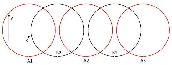
Figure 3.
Case 1: geometry analyzed for Case 1. In red the transmitting coils and in black the receiving coils.
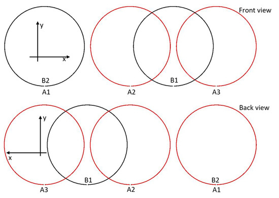
Figure 4.
Case 2: geometry analyzed for Case 2. In red the transmitting coils and in black the receiving coils.
- Case 1,,,,;
- Case 2,,,,.
The value assumed for the parameter is 10 .
Considering that for the analyzed cases all the coils are identical (same geometry and material), all the inductors and the resistors modeling the inductor losses assume the same value (see Figure 2): for , , for , for , , for .
The problem has been analyzed by using the time-domain solver of the full-wave simulator CST MICROWAVE STUDIO and the circuital simulator AWR Design Environment. First of all, a full-wave simulation of a single coil has been performed in order to calculate L and R; then, the value of the lumped capacitor to be added in series configuration with the coils has been calculated so to have a frequency of resonance of . The calculated values are summarized in Table 1. After that, full-wave simulations have been performed for the configurations corresponding to Case 1 and Case 2 obtaining the following impedance matrices:

Table 1.
Parameters of the equivalent circuit and optimal loads for Case 1. and (or and ) are the optimal compensating capacitors (or inductors) to be used for the receiver i and the transmitter j.
Starting from (71) and (72) the values reported in Table 1 and Table 2 have been derived for the coupling coefficients corresponding to the two analyzed configurations.
Table 2.
Parameters of the equivalent circuit and optimal loads for Case 2. and (or and ) are the optimal compensating capacitors (or inductors) to be used for the receiver i and the transmitter j.
According to the theory presented in Section 2, the impedance matrices given in (71) and in (72) have been used for calculating the matrices , , , and , then the generalized eigenvalue problem expressed in (21) has been solved. For Case 1 the following eigenvalues have been obtained:
Accordingly, for Case 1 and , thus corresponding to a maximum realizable gain equal to 0.975. For Case 2, the calculated eigenvalues are:
Accordingly, for Case 2 and , thus corresponding to a maximum realizable gain equal to 0.994.
The analytical data calculated from the theory for the optimal terminating impedances for Case 1 and Case 2 are summarized in Table 1 and Table 2. These values were calculated as ratios of the optimal currents, that are the eigenvectors obtained from (21), and the corresponding voltages.
In more detail, by setting for both the analyzed cases 1, the following values have been obtained for the other two input currents
- Case 1: , 1,
- Case 2: , .
For Case 1 the analytically calculated values for the optimal voltages in [V] are:
thus corresponding to the following optimal terminating impedances in []:
It can be seen that the imaginary parts of the optimal terminating impedances are positive thus corresponding to the series compensating inductors reported in Table 1. According to these results, the optimal sources can be implemented by using three voltage generators delivering the voltages expressed in (32), i.e.,
and having the impedances expressed in (76) in series configuration. With regard to the imaginary parts of the optimal terminations, as observed in Section 4, purely resistive values could be used for both the loads and the generators impedances by adjusting the values of the series capacitors C so to include the reactances reported in (76).
The optimal voltages in [V] calculated for Case 2 are:
and correspond to the following optimal terminating impedances in []:
while the optimal voltages to be delivered by the generators are:
For Case 2 it can be seen that the imaginary parts of the optimal terminating impedances are negative thus corresponding to the series compensating capacitors reported in Table 2.
The analytical data were validated through circuital simulations. In more detail, simulations were performed by modeling the links corresponding to Case 1 and Case 2 as black box components described by the impedance matrix calculated through full-wave simulations and reported in (71) and in (72), respectively. The transmitters ports were connected to voltage generators with series complex impedances, while the receivers ports were terminated on complex impedances.
The results obtained for Case 1 are reported in Figure 5, Figure 6, Figure 7 and Figure 8. In this case the voltages of the generators and the impedances were set according to (76)–(77). Figure 5 illustrates the behavior of the power gain as function of the resistive part of the load impedances . In particular, the figure compares the result obtained with and without the reactive parts of all the terminating impedances. As it can be seen from Figure 5, has its maximum for , thus confirming theoretical data. However, it can be also seen that the reactive parts of the terminating impedances have a negligible effect on the power gain, this is probably due to the small values of the coupling coefficient between the receivers. The behavior of as function of the compensating reactances is further investigated in Figure 6 where as function of the load inductors is reported. It can be seen that for values of the load inductance up to about 100 has a very small dependence on ; thus confirming that for the analyzed case the reactances of the loads do not play a key role.
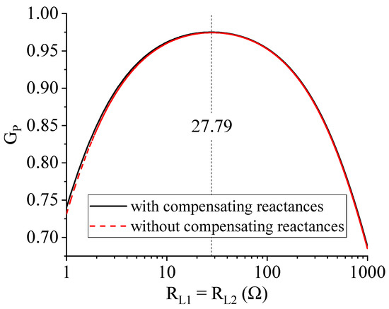
Figure 5.
Case 1: efficiency calculated for Case 1 by varying the resistive part of the loads while all the other parameters are set to the optimal values.
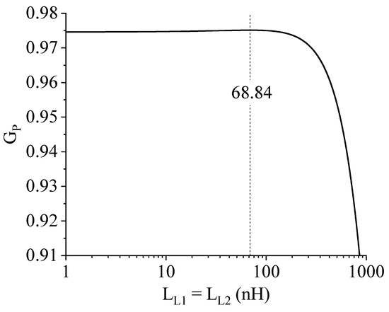
Figure 6.
Case 1: efficiency calculated for Case 1 by varying the compensating inductor of the loads, i.e., while all the other parameters are set to the optimal values.
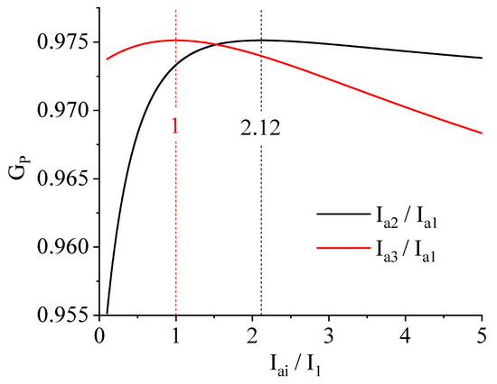
Figure 7.
Case 1: efficiency calculated for Case 1 by varying the ratio of the input currents while all the other parameters are set to the optimal values.
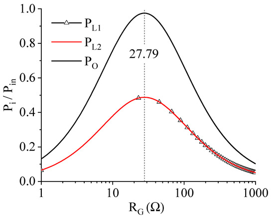
Figure 8.
Case 1: output power calculated for Case 1 by varying the (i.e., the resistive part of the impedances of the generators).
The dependence on the generators has been also investigated. Figure 7 shows the results obtained by varying the ratios of the current delivered by the generators, while Figure 8 shows the power delivered to the loads as function of the generators impedances . Both figures confirm the theory; in particular, from Figure 8 it can be seen that the input power is divided equally between the two loads and that the output power has a strong dependence on .
The results obtained for Case 2 are given in Figure 9, Figure 10 and Figure 11. Also in this case data obtained from simulations are in a perfect agreement with the theory. It is worth observing the results obtained for the output power as function of . As it can be seen, as a result of the application of the presented theory the power transfer takes place substantially between the transmitter connected at port and the receiver connected at port . In fact, due to the coupling between and , that is definitely stronger than all the other couplings, in order to maximize the power gain the application of the theory leads to a configuration where most of the input power is provided by the first transmitter and delivered to the second receiver. This result is due to the optimized figure of merit, i.e., the power gain as defined in (10), and highlights that, in the case where it is important to supply to each receiver a minimum power value, a different figure of merit should be introduced and optimized.
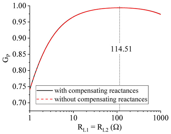
Figure 9.
Case 2: efficiency calculated for Case 2 by varying while all the other parameters are set to the optimal values.
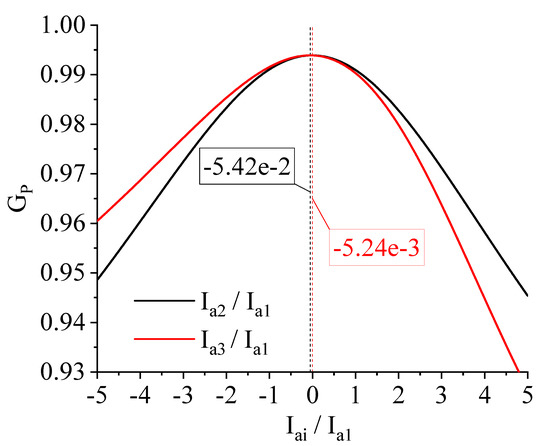
Figure 10.
Case 2: efficiency calculated for Case 2 by varying the ratio of the input currents while all the other parameters are set to the optimal values.
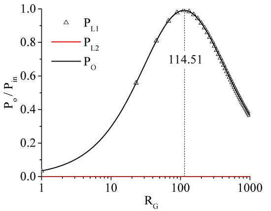
Figure 11.
Case 2: output power calculated for Case 2 by varying the resistive part of the impedances of the generators, .
6. Conclusions
In this paper the problem of efficiency maximization has been solved for a resonant inductive WPT link using multiple transmitters and receivers (MIMO configuration). For a WPT link with M transmitters and N loads, the efficiency is defined as the ratio of the sum of the powers delivered to the N loads and the sum of the powers entering the network from the M ports connected to the transmitters. The general expressions of the optimal loads and the optimal source impedances are presented. The proposed theory is general and can be applied to any possible MIMO WPT link. For this reason, the presented procedure can be adopted in several application scenarios; it can be exploited: (1) for maximizing the efficiency of already fabricated MIMO links, starting from their measured impedance matrix the optimal terminations can be determined, or (2) for designing new WPT links through the evaluation of the maximum realizable efficiency for different configurations of the coils.
Among the various application scenarios, the presented theory could be adopted in designing MISO/SIMO/MIMO links for medical implants, for a desk for wireless recharge of multiple devices, and in general for all applications where it is necessary to recharge multiple devices or to obtain performance robust with respect to misalignment problems.
An example of application of the presented approach has been presented starting from the impedance matrix of a 3-TX and 2-RX calculated through full-wave simulations. The reported results validate the presented theory and demonstrate that its exploitation is simple and straightforward.
Author Contributions
Conceptualization, methodology, and validation, G.M. and M.M.; writing—original draft preparation, G.M. and M.M.; writing—review and editing, G.M., M.M., B.M., A.C., and L.T. All authors have read and agreed to the published version of the manuscript.
Funding
This research received no external funding.
Institutional Review Board Statement
Not applicable.
Informed Consent Statement
Not applicable.
Data Availability Statement
Not applicable.
Acknowledgments
The authors would like to remember the colleague Franco Mastri who suddenly passed away on 3 April 2020. He was a great colleague and a profound scientist. Fundamental discussions and studies on the theoretical modeling of near-field WPT systems were of great inspiration also for the results presented in this work.
Conflicts of Interest
The authors declare no conflict of interest.
Appendix A. Some Insights into the Generalized Eigenvalue Problem
In this section a proof is given for the statement that, for each finite nonzero eigenvalue of problem (12), also is an eigenvalue of (12). It will also be demonstrated that .
This statement can be demonstrated by noting that the determinant of can be expanded as
where
and represents the identity matrix of size M. Equation (A1) shows that there are always (at least) eigenvalues equal to 1, and that the remaining eigenvalues occur in pairs . In fact, it can be observed that and are symmetric matrices, while is skew symmetric and, consequently, is Hermitian. Hence it results
As a consequence, if is the maximum eigenvalue, then .
Equation (A1) also suggests that problem (21) can be transformed into a quadratic eigenvalue problem involving matrices. This can be obtained by rewriting (21) as
and by eliminating from (A4), which yields
In order to solve problem (A4), it can be transformed into a linear generalized eigenvalue problem of size by letting
which allows us to rewrite (A4) as
Finally, it can be noted that is a positive definite matrix. In fact it can be written as
where the two factors are positive definite matrices, since the first factor is the inverse of a positive definite matrix and the second one is the Schur complement of the block in the positive definite matrix . Hence (A7) can be turned into the ordinary eigenvalue problem
where
is the Cholesky factorization of . After solving (A9), the currents at the ports of set can be computed by the second of (A4).
In the general case the solution of (A5) is quite involved, hence, unless , it is preferable to solve (21), directly. However, the reduction to the quadratic problem is particularly advantageous if it results . This happens, for instance, in the cases, frequently encountered in the study of WPT systems, where the coupling matrix is purely real or purely imaginary. If and , (A5) can be rewritten as
with
while, if and , (A5) can be rewritten as
with
hence, in both cases, (A5) is reduced to an ordinary eigenvalue problem of size .
References
- Karalis, A.; Joannopoulos, J.D.; Soljačić, M. Efficient wireless non-radiative mid-range energy transfer. Ann. Phys. 2008, 323, 34–48. [Google Scholar] [CrossRef]
- Monti, G.; Paolis, M.V.D.; Corchia, L.; Tarricone, L. Wireless Resonant Energy link for Pulse Generators Implanted in the Chest. IET Microwaves Antennas Propag. 2017, 11, 2201–2210. [Google Scholar] [CrossRef]
- Carvalho, N.B.; Georgiadis, A.; Costanzo, A.; Stevens, N.; Kracek, J.; Pessoa, L.; Roselli, L.; Dualibe, F.; Schreurs, D.; Mutlu, S.; et al. Europe and the future for WPT. IEEE Microw. Mag. 2017, 18, 56–87. [Google Scholar] [CrossRef]
- Rim, C.T.; Mi, C. Wireless Power Transfer for Electric Vehicles and Mobile Devices; Wiley-IEEE Press: Hoboken, NJ, USA, 2017. [Google Scholar]
- Inagaki, N. Theory of Image Impedance Matching for Inductively Coupled Power Transfer Systems. IEEE Trans. Microw. Theory Tech. 2014, 62, 901–908. [Google Scholar] [CrossRef]
- Monti, G.; Costanzo, A.; Mastri, F.; Mongiardo, M. Optimal design of a wireless power transfer link using parallel and series resonators. Wirel. Power Transf. 2016, 3, 105–116. [Google Scholar] [CrossRef]
- Monti, G.; Costanzo, A.; Mastri, F.; Mongiardo, M.; Tarricone, L. Rigorous design of matched wireless power transfer links based on inductive coupling. Radio Sci. 2016, 51, 858–867. [Google Scholar] [CrossRef]
- Zhang, W.; Wong, S.; Tse, C.K.; Chen, Q. Design for Efficiency Optimization and Voltage Controllability of Series–Series Compensated Inductive Power Transfer Systems. IEEE Trans. Power Electron. 2014, 29, 191–200. [Google Scholar] [CrossRef]
- Zhang, W.; Wong, S.; Tse, C.K.; Chen, Q. Analysis and Comparison of Secondary Series- and Parallel-Compensated Inductive Power Transfer Systems Operating for Optimal Efficiency and Load-Independent Voltage-Transfer Ratio. IEEE Trans. Power Electron. 2014, 29, 2979–2990. [Google Scholar] [CrossRef]
- Mastri, F.; Mongiardo, M.; Monti, G.; Dionigi, M.; Tarricone, L. Gain expressions for resonant inductive wireless power transfer links with one relay element. Wirel. Power Transf. 2018, 5, 27–41. [Google Scholar] [CrossRef]
- Lee, J.; Lee, K. Effects of Number of Relays on Achievable Efficiency of Magnetic Resonant Wireless Power Transfer. IEEE Trans. Power Electron. 2020, 35, 6697–6700. [Google Scholar] [CrossRef]
- Alberto, J.; Reggiani, U.; Sandrolini, L.; Albuquerque, H. Accurate calculation of the power transfer and efficiency in resonator arrays for inductive power transfer. PIER 2019, 83, 61–76. [Google Scholar] [CrossRef]
- Johari, R.; Krogmeier, J.; Love, D. Analysis and practical considerations in implementing multiple transmitters for wireless power transfer via coupled magnetic resonance. IEEE Trans. Ind. Electron. 2014, 61, 1774–1783. [Google Scholar] [CrossRef]
- Yoon, I.; Ling, H. Investigation of near-field wireless power transfer under multiple transmitters. IEEE Antenna Wirel. Propag. Lett. 2011, 10, 662–665. [Google Scholar] [CrossRef]
- Lang, H.D.; Ludwig, A.; Sarris, C.D. Convex Optimization of Wireless Power Transfer Systems With Multiple Transmitters. IEEE Trans. Antennas Propag. 2014, 62, 4623–4636. [Google Scholar] [CrossRef]
- Pacini, A.; Costanzo, A.; Aldhaher, S.; Mitcheson, P.D. Load- and Position-Independent Moving MHz WPT System Based on GaN-Distributed Current Sources. IEEE Trans. Microw. Theory Tech. 2017, 65, 5367–5376. [Google Scholar] [CrossRef]
- Monti, G.; Che, W.; Wang, Q.; Costanzo, A.; Dionigi, M.; Mastri, F.; Mongiardo, M.; Perfetti, R.; Tarricone, L.; Chang, Y. Wireless Power Transfer With Three-Ports Networks: Optimal Analytical Solutions. IEEE Trans. Circuits Syst. 2017, 64-I, 494–503. [Google Scholar] [CrossRef]
- Li, Y.; Song, K.; Li, Z.; Jiang, J.; Zhu, C. Optimal Efficiency Tracking Control Scheme Based on Power Stabilization for a Wireless Power Transfer System with Multiple Receivers. Energies 2018, 11, 1232. [Google Scholar] [CrossRef]
- Sejin, K.; Hwang, S.; Kim, S.; Lee, B. Investigation of Single-Input Multiple-Output Wireless Power Transfer Systems Based on Optimization of Receiver Loads for Maximum Efficiencies. J. Electromagn. Eng. Sci. 2018, 18, 145–153. [Google Scholar]
- Fu, M.; Zhang, T.; Ma, C.; Zhu, X. Efficiency and Optimal Loads Analysis for Multiple-Receiver Wireless Power Transfer Systems. IEEE Trans. Microw. Theory Tech. 2015, 63, 3463–3477. [Google Scholar] [CrossRef]
- Monti, G.; Dionigi, M.; Mongiardo, M.; Perfetti, R. Optimal Design of Wireless Energy Transfer to Multiple Receivers: Power Maximization. IEEE Trans. Microw. Theory Tech. 2017, 65, 260–269. [Google Scholar] [CrossRef]
- Fu, M.; Yin, H.; Ma, C. Megahertz Multiple-Receiver Wireless Power Transfer Systems With Power Flow Management and Maximum Efficiency Point Tracking. IEEE Trans. Microw. Theory Tech. 2017, 65, 644–654. [Google Scholar] [CrossRef]
- Duong, Q.T.; Okada, M. Maximum efficiency formulation for inductive power transfer with multiple receivers. IEICE Electron. Exp. 2016, 22, 20160915. [Google Scholar] [CrossRef][Green Version]
- Duong, Q.; Okada, M. Maximum Efficiency Formulation for Multiple-Input Multiple-Output Inductive Power Transfer Systems. IEEE Trans. Microw. Theory Tech. 2018, 66, 3463–3477. [Google Scholar] [CrossRef]
- Monti, G.; Mongiardo, M.; Minnaert, B.; Costanzo, A.; Tarricone, L. Optimal Terminations for a Single-Input Multiple-Output Resonant Inductive WPT Link. Energies 2020, 13, 5157. [Google Scholar] [CrossRef]
- Yuan, Q.; Aoki, T. Practical applications of universal approach for calculating maximum transfer efficiency of MIMO-WPT system. Wirel. Power Transf. 2020, 7, 86–94. [Google Scholar] [CrossRef]
- Desoer, C.A. The maximum power transfer theorem for n-ports. IEEE Trans. Circuit Theory 1973, 20, 328–330. [Google Scholar] [CrossRef]
Publisher’s Note: MDPI stays neutral with regard to jurisdictional claims in published maps and institutional affiliations. |
© 2021 by the authors. Licensee MDPI, Basel, Switzerland. This article is an open access article distributed under the terms and conditions of the Creative Commons Attribution (CC BY) license (https://creativecommons.org/licenses/by/4.0/).