
The Influence of Temperature on Degradation of Oil and Gas Tubing Made of L80-1 Steel


Abstract
1. Introduction
- Adsorption and chemisorption, that is, accumulation of substances originating from the gas on the metal surface, as a result of the formation of surface chemical connections with metal, creating a thin oxidation layer;
- Origination of oxidation products on the absorption surface of the corrosion layer, and integrated into the crystalline lattice of the scale;
- Diffusion/flow of metal ions to the formed scale.
- Creating a passivation layer on the surface via the growth of insoluble metal oxide on the surface. These bonds create a protective barrier coating, which becomes an impermeable layer, and, at the same time, it is very flexible and adheres well to the substrate [24]. Phosphates and chromates are typical examples of such an application;
- Neutralising ions, which cause corrosion in the environment. Neutralising amines and ammonia are typical components of such an inhibitor. These are inhibitors that are effective in boiler waters and in slightly acid environments;
- Removing caustic ions from the solution. In-hydrazine and sodium sulphate are typical components of the inhibitor. Such inhibitors remove oxygen dissolved in water.
2. Experimental Procedure
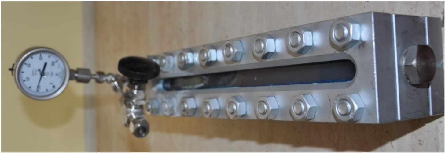
2.1. Methodology
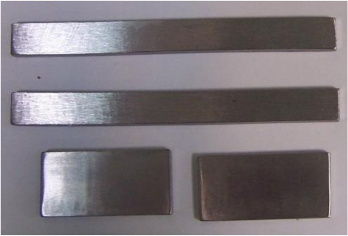
2.2. Materials
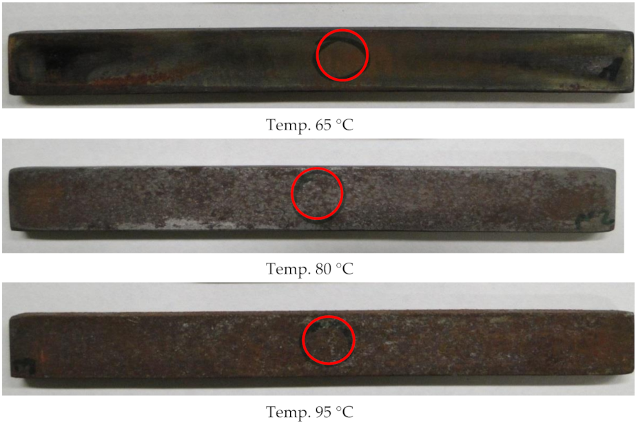
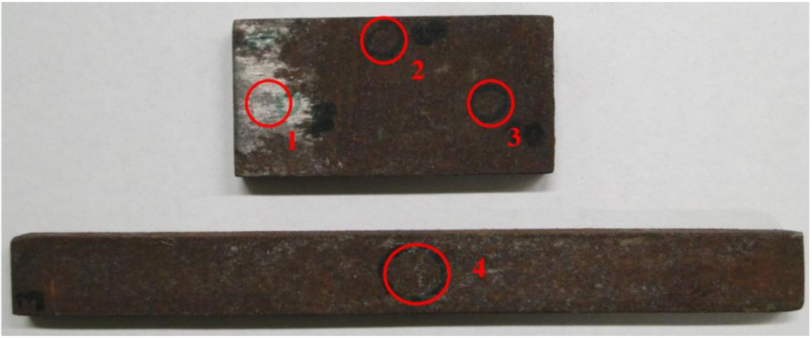
3. Results and Discussion

| 5. |  | Element | Wt. % | At. % |
| O | 14.77 | 36.73 | ||
| Cl | 5.18 | 5.81 | ||
| Fe | 78.99 | 56.26 | ||
| Si | 0.60 | 0.85 | ||
| Cr | 0.46 | 0.35 | ||
| Total | 100.00 | 100.00 |

4. Conclusions
Funding
Institutional Review Board Statement
Informed Consent Statement
Data Availability Statement
Conflicts of Interest
References
- Ribeiro, L.P.; Paulo, C.A.S.; Neto, E.A. Compos Basin-Subsea Equipment: Evolution and Next Steps. In Proceedings of the Offshore Technology Conference, Richardson, TX, USA, 5–8 May 2003; p. 15223. [Google Scholar]
- Estrella, G. The Importance of Brazilian Deepwater Activities to the Oil Industry Technological Development. In Proceedings of the Offshore Technology Conference, Richardson, TX, USA, 5–8 May 2003; p. 15049. [Google Scholar]
- Yougui, Z. Electrochemical Mechanism and Model of H2S Corrosion of Carbon Steel. Ph.D. Thesis, Ohio University, Athens, GA, USA, 2015. [Google Scholar]
- Mahmoodian, M.; Qingi, C. Failure assessment and safe life prediction of corroded oil and gas pipelines. J. Pet. Sci. Eng. 2017, 151, 434–438. [Google Scholar] [CrossRef]
- Wang, W.; Natelson, R.; Stikeleather, L.; Roberts, W. CFD simulation of transient stage of continuous countercurrent hydrolysis of canola oil. Comput. Chem. Eng. 2012, 43, 108–119. [Google Scholar] [CrossRef]
- Nesic, S. Key issues related to modelling of internal corrosion of oil and gaspipelines—A review. Corros. Sci. 2007, 49, 4308–4338. [Google Scholar] [CrossRef]
- Revie, R. Oil, Gas Pipelines. In Integrity and Safety Handbook; John Wiley & Sons, Inc.: Hoboken, NJ, USA, 2015. [Google Scholar]
- Papavinasm, S. Corrosion Control in the Oil and Gas Industry; Elsevier: Houston, TX, USA, 2013. [Google Scholar]
- Kermani, B.; Cochrane, R.; Dougan, M.; Linne, C.; Gonzalez, J. Development of low carbon Cr-Mo steels with exceptional corrosion resistance for oilfield applications. In Proceedings of the 56th NACE Annual Conference, Houston, TX, USA, 11–16 March 2001; Available online: https://www.onepetro.org/conferencepaper/NACE-03117 (accessed on 13 October 2021).
- Stachowicz, A. Korozja rur wydobywczych odwiertów gazowych zawierających CO2. Nafta-Gaz 2011, 11, 395–400. (In Polish) [Google Scholar]
- Zhang, G.A.; Liu, D.; Li, Y.Z.; Guo, X.P. Corrosion behavior of N80 carbon steel in formation water under dynamic supercritical CO2 condition. Corros. Sci. 2017, 120, 107–120. [Google Scholar] [CrossRef]
- Stachowicz, A. Korozja rur w odwiertach oraz dobór ochrony inhibitowanej w płynach nadpakerowych. Nafta-Gaz 2013, 7, 525–531. (In Polish) [Google Scholar]
- Atiwat, K. Lifetime Estimation of Steel Tubing by Corrosion Analysis for Petroleum. Master’s Thesis, Geotechnology Suranaree University of Technology, Nakhon Ratchasima, Thailand, 2016. [Google Scholar]
- Choi, Y.S.; Young, D.; Nesic, S. Effect of Impurities on the Corrosion Behavior of CO2 Transmission Pipeline Steel in Supercritical CO2-Water Environment. Environ. Sci. Technol. 2010, 44, 9233–9238. [Google Scholar] [CrossRef] [PubMed]
- Choi, Y.S.; Nesic, S. Determining the Corrosive Potential of CO2 Transport Pipeline in High pCO2–Water Environments. Int. J. Greenh. Gas Control 2011, 5, 788. [Google Scholar] [CrossRef]
- Zhang, Y.; Pang, X.; Qu, S.; Gao, X.; Li, K. The relationship between fracture toughness of CO2 corrosion scale and corrosion rate of X65 pipeline steel under supercritical CO2 condition. Int. J. Greenh. Gas Control 2011, 5, 1643–1650. [Google Scholar] [CrossRef]
- Zhang, Y.; Pang, X.; Qu, S.; Gao, X.; Li, K. Discussion of the CO2 corrosion mechanism between low partial pressure and supercritical condition. Corros. Sci. 2012, 59, 186–197. [Google Scholar] [CrossRef]
- Suhor, M.F.; Mohamed, M.F.; Nor, A.M.; Singer, M.; Nesic, S. Corrosion of mild steel in high CO2 environment: Effect of the FeCO3 layer. In Proceedings of the Corrosion 2012, Salt Lake City, UT, USA, 11–15 March 2012; p. 0001434. [Google Scholar]
- Cui, Z.D.; Wu, S.L.; Zhu, S.L.; Yang, X.J. Study on Corrosion Properties of Pipelines in Simulated Produced Water Saturated with Supercritical CO2. Appl. Surf. Sci. 2006, 252, 2368. [Google Scholar] [CrossRef]
- Osokogwu, U.; Oghenekaro, E. Evaluation of corrosion inhibitors effectiveness in oilfield production operations. Int. J. Sci. Technol. Res. 2012, 1, 19–23. [Google Scholar]
- Banaś, J.; Mazurkiewicz, B.; Solarski, W. Problem korozji mikrobiologicznej w instalacjach geotermalnych. Ochr. Przed Korozją 2011, 3, 76–81. (In Polish) [Google Scholar]
- Bęben, D. Ochrona chemiczna metali przed korozją na przykładzie wybranych kopalń gazu ziemnego. Ochr. Przed Korozją 2014, 12, 478–481. (In Polish) [Google Scholar]
- Bęben, D. Badania skuteczności działania wybranych inhibitorów korozji stosowanych okresowo w przemyśle wydobywczym. Ochr. Przed Korozją 2019, 62, 376–381. (In Polish) [Google Scholar]
- PN-70/H-04600 Korozja metali. Badanie odporności korozyjnej metali i stopów. Ogólne wytyczne. (In Polish)
- PN-76/H-04601 Korozja metali. Badania laboratoryjne w cieczach i roztworach w temperaturze otoczenia. (In Polish)
- PN-78/H-04608 Korozja metali. Skala odporności metali na korozji. (In Polish)
- PN-78/H-04610 Korozja metali. Metody oceny badań korozyjnych. (In Polish)
- Młynarski, A.; Piasecki, A.; Jakubowski, J. Badania mikroskopowe i strukturalne skorodowanych próbek stali L80-1. Politech. Poznańska. Poznań 2012, 699–702. (In Polish) [Google Scholar]
- Zhang, X.; Zevenbergen, J.; Benedictus, T. Corrosion Studies on Casing Steel in CO2 Storage Environments. Energy Procedia 2013, 37, 5816–5822. [Google Scholar] [CrossRef][Green Version]
- Eliyan, F.F.; Alfantazi, A. Influence of temperature on the corrosion behavior of API-X100 pipeline steel in 1-bar CO2-HCO3− solutions: An electrochemical study. Mater. Chem. Phys. 2013, 140, 508–515. [Google Scholar] [CrossRef]
- El Alami, H.; Augustin, C.; Orlans, B.; Servier, J.J. Carbon Capture and Storage projects: Material integrity for CO2 injection and storage. Eurocorr 2011, 2011, 4741. [Google Scholar]
- Choi, Y.S.; Farelas, F.; Neši, S.; Magalhães, A.A.O.; Andrade, C.D.A. Corrosion behavior of deep water oil production tubing material under supercritical CO2 environment: Part 1-effect of pressure and temperature. Corrosion 2014, 70, 38–47. [Google Scholar] [CrossRef]
- Jakubowski, M. Influence of pitting corrosion on fatigue and corrosion fatigue of ship structures Part I Pitting corrosion of ship structures. Pol. Marit. Res. 2014, 81, 62–69. (In Polish) [Google Scholar] [CrossRef]
- Li, D.; Liu, Q.; Wang, W.; Jin, L.; Xiao, H. Corrosion Behavior of AISI 316L Stainless Steel Used as Inner Lining of Bimetallic Pipe in a Seawater Environment. Materials 2021, 14, 1539. [Google Scholar] [CrossRef] [PubMed]
- Zhang, D.; Gao, X.; Li, W.; Li, B.; Guo, J.; Zhang, J.; Pang, Q.; Xu, Z. CO2 corrosion behavior of high-strength martensitic steel for marine riser exposed to CO2-saturated salt solution. Mater. Res. Express 2021, 8, 076517. [Google Scholar] [CrossRef]


| Variable | Value | Standard Deviation |
|---|---|---|
| Temperature [°C] | 20.0 | 1.5 |
| Density [g/cm3] | 1.182 | 0.001 |
| pH | 4.8 | 1.5 |
| Eh [mV] | 117.8 | 1.12 |
| Carbonates [mg/dm3] | n.s. | n.s. |
| Hydrogencarbonates [mg/dm3] | 152 | 15.6 |
| Chlorides [mg/dm3] | 148.000 | 38.540 |
| Calcium [mg/dm3] | 29.260 | 9.230 |
| Magnesium [mg/dm3] | 5.350 | 1.320 |
| Potassium [mg/dm3] | 590 | 62 |
| CO2 [wt. %] | 0.6 | 0.1 |
| H2S [wt. %] | 0.15 | 0.01 |
| C [%] | Mn [%] | Si [%] | P [%] | S [%] | Al [%] | Ni [%] | Mb [%] | Cr [%] | V [%] | Fe [%] |
|---|---|---|---|---|---|---|---|---|---|---|
| 0.26 | 1.25 | 0.24 | 0.012 | 0.004 | 0.018 | 0.11 | 0.23 | 0.08 | 0.006 | Bal. |
| 1. |  | Element | Wt. % | At. % |
| O | 9.88 | 27.57 | ||
| Cl | 0.79 | 0.99 | ||
| Fe | 89.33 | 71.44 | ||
| Total | 100.00 | 100.00 | ||
| 2. |  | Element | Wt. % | At. % |
| O | 18.83 | 44.38 | ||
| Cl | 0.72 | 0.96 | ||
| Fe | 0.92 | 0.98 | ||
| Si | 79.52 | 53.68 | ||
| Total | 100.00 | 100.00 | ||
| 3. |  | Element | Wt. % | At. % |
| O | 16.17 | 40.00 | ||
| Cl | 0.46 | 0.51 | ||
| Fe | 82.59 | 58.52 | ||
| Si | 0.57 | 0.81 | ||
| Cr | 0.20 | 0.15 | ||
| Total | 100.00 | 100.00 | ||
| 4. |  | Element | Wt. % | At. % |
| O | 17.60 | 41.31 | ||
| Cl | 8.51 | 9.02 | ||
| Fe | 73.89 | 49.68 | ||
| Total | 100.00 | 100.00 |
Publisher’s Note: MDPI stays neutral with regard to jurisdictional claims in published maps and institutional affiliations. |
© 2021 by the author. Licensee MDPI, Basel, Switzerland. This article is an open access article distributed under the terms and conditions of the Creative Commons Attribution (CC BY) license (https://creativecommons.org/licenses/by/4.0/).
Share and Cite
Bęben, D. The Influence of Temperature on Degradation of Oil and Gas Tubing Made of L80-1 Steel. Energies 2021, 14, 6855. https://doi.org/10.3390/en14206855
Bęben D. The Influence of Temperature on Degradation of Oil and Gas Tubing Made of L80-1 Steel. Energies. 2021; 14(20):6855. https://doi.org/10.3390/en14206855
Chicago/Turabian StyleBęben, Dariusz. 2021. "The Influence of Temperature on Degradation of Oil and Gas Tubing Made of L80-1 Steel" Energies 14, no. 20: 6855. https://doi.org/10.3390/en14206855
APA StyleBęben, D. (2021). The Influence of Temperature on Degradation of Oil and Gas Tubing Made of L80-1 Steel. Energies, 14(20), 6855. https://doi.org/10.3390/en14206855