Abstract
The discrimination of inrush currents and internal fault currents in transformers is an important feature of a transformer protection scheme. The harmonic current restrained feature is used in conventional differential relay protection of transformers. A literature survey shows that the discrimination between the inrush currents and internal fault currents is still an area that is open to research. In this paper, the classification of internal fault currents and magnetic inrush currents in the transformer is performed by using an extended Kalman filter (EKF) algorithm. When a transformer is energized under normal conditions, the EKF estimates the primary side winding current and, hence, the absolute residual signal (ARS) value is zero. The ARS value will not be equal to zero for internal fault and inrush phenomena conditions; hence, the EKF algorithm will be used for discriminating the internal faults and inrush faults by keeping the threshold level to the ARS value. The simulation results are compared with the theoretical analysis under various conditions. It is also observed that the detection time of internal faults decreases with the severity of the fault. The results of various test cases using the EKF algorithm are presented. This scheme provides fast protection of the transformer for severe faults.
1. Introduction
Transformers require an efficient protection system from faulty conditions in the power system network. The classification of magnetic inrush currents and internal fault currents is a challenging issue for proper relay design. The magnetizing inrush current results in maloperation of the differential relay in transformer protection. The transformer may become saturated with inrush currents and internal faults due to the presence of zero-sequence components, which may lead to maloperation of differential current protection. The waveform correlation technique is suggested for differential current protection of transformers. The analysis of zero sequence currents due to inrush currents and internal faults can be performed using the waveform correlation technique [1].
An accelerated Convolutional neural network (CNN) was suggested for estimating the transformer magnetizing current from internal faults on a 230 kV transmission network. It was observed that the CNN can have feature extraction and fault detection blocks in a single deep neural network block by enabling the system to provide important features automatically [2]. The fundamental theory and principles of magnetizing the inrush current of the transformer are essential when it is energized. The analysis of the magnetizing current is important for transformer protection [3]. A new technique was proposed with two moving windows to predict the magnitude of differential currents of the transformer for the discrimination of inrush currents from internal faults [4]. The least error square (LES) was proposed to classify the fault currents and the magnitude of magnetic inrush currents with the two moving windows technique. The LES method has a very fast response capability with good estimation. A new method was proposed for the classification of fault currents and magnetic inrush currents of the transformer by using measurement of similarity index between the updated new sequence and a prescribed template. The proposed technique was used to sort the sample points of differential currents and fault currents to classify the fault currents and magnetic inrush currents [5].
The discrimination of the inrush currents from the internal faults in power transformers was suggested based on the runs test method, which is derived from the inherent differences between the waveforms [6]. A short time correlation transform was used to discriminate the internal fault current and inrush current by extracting the dead angle from the differential current. The effect of current-transformer (CT) saturation on the inrush current was also considered for proper discrimination of the faults [7].
Discrete wavelet transform (DWT) was suggested for the separation of magnetic inrush currents and fault currents by extracting the energy functions. DWT as used with different wavelet functions to achieve higher accuracy and reliability [8]. The saturation of the transformer will affect the classification of magnetic inrush currents and fault currents of a single-phase transformer. An efficient compensation algorithm was suggested for the discrimination of magnetic inrush currents and fault currents, which are affected by CT saturation [9].
The EKF algorithm as used to predict the primary winding current for the classification of magnetic inrush currents and fault currents. The EKF algorithm was used to estimate the primary side winding current of the transformer based on the residual current [10]. The novel method was used for the classification of internal fault currents and inrush currents based on the two-terminal network method. The absolute difference of the active power (ADOAP) flowing into and consumed by the two-terminal network was considered, so that the internal faults were identified [11]. The high-temperature resistive Superconducting Fault Current Limiters (SFCL) is suggested for discrimination of an internal fault from inrush current of transformer. The SFCL will operate for high fault currents, which gives more sensitivity than the differential protection [12]. The internal and external electrical faults and inrush current of the transformer are can be analysed using Maximal Overlap Discrete Wavelet Transform (MODWT) with Daubechies4 wavelet function by extracting their features. These extracted features are considered for training the classifiers of Decision Tree (DT) and Artificial Neural Network (ANN) [13].
The wavelet transform is one of the signal processing techniques that are used for feature extraction and fault analysis. The discrimination of electromagnetic transients and internal faults were also estimated by using wavelet transform analysis [14]. The wavelet pocket transform (WPT) has more features than the fast wavelet transform (FWT) to discriminate signals in both time and frequency domains. The WPT is an accurate method for the characterization of signals for both the frequency and time domains [15].
The sine wave curve-fitting was suggested for classifying the magnetic inrush currents and internal fault currents for three-phase transformers. The sinusoidal wave was fit to the normalized differential current (Idiff) by utilizing least squares techniques (LSQ) for every individual phase. The calculation of residual signals is based on the difference between normalized differential currents and fitted signals. The prediction of internal fault currents and magnetic inrush currents by using the residual signals may be possible in less than 10 ms, i.e., half cycle of power frequency [16]. A review of the reliability and safety of high-speed trains with advanced branches of intelligent transportation was performed by using fault detection and diagnosis techniques. This literature review will help with the fault detection of high-speed trains, and it suggests an advanced method for future investigation [17]. The fault detection and diagnosis (FDD) of high-speed trains in electric traction is suggested based on modified principal component analysis and a broad learning system. The broad learning system can be used to extract fault information without requiring mathematical models or a control mechanism for high-speed trains [18]. The hybrid KNN-GA is used for differential protection of the transformer, i.e., discrimination of magnetic inrush current and fault current with improved performance. The proposed algorithm also increases the performance of the deferential relay [19]. The inrush currents and fault currents are distinguished by the novel method, i.e., generalized delayed signal cancelation (GDSC), based on the sequence components along with the fundamental component. The fundamental, second harmonic positive and negative sequence components are calculated for the estimation of internal faults and magnetic inrush currents [20].
The discrimination of transformer fault currents and magnetic inrush currents is achieved by multi-scale multivariate fuzzy entropy (MMFE), by applying the fuzzy membership function. The MMFE renders better results than the WT method for classification of fault currents and inrush currents, based on the comparison of numerical values of the fixed value of current [21]. The extraction of features with the measured data from the differential currents of a power transformer is suggested by using random the forest-based fault discrimination (RFBFD) technique [22]. New techniques, such as LES, DWT and EKF, are suggested for analysis and estimation of the current from the measured waveform. It is observed that the DWT is given detailed coefficients for current estimation with the varying window technique and EKF is suggested for current estimation with the prediction and correction method.
From the above analysis of the literature survey, it is observed that discrimination of internal fault currents and inrush currents is still a problem for researchers. In this paper, a novel technique is presented for the classification of internal fault currents from the inrush currents using the EKF algorithm.
In this paper, an EKF algorithm is explored to predict primary side currents of the transformer, using the nonlinear state-space transformer model. A residual signal is derived from the difference of measured and estimated currents on the primary side winding of the transformer. When the transformer is under normal conditions, the residual signal becomes zero based on the EKF estimation. If the transformer is in a faulty condition, large residual currents are generated. The residual signal amplitude is compared with the threshold value in order to classify the magnetic inrush current and internal fault current. In this paper, the diagonal elements of the covariance matrix are utilized to analyze the severity of the fault occurrence in the transformer. The nonlinear state-space model of the one-phase transformer is developed under steady-state conditions and the proposed EKF algorithm in the next sections. The simulation results are presented to evaluate the EKF for different conditions of the transformer.
2. Transformer State-Space Nonlinear Model
According to the literature [10], the nonlinear state-space model for the transformer is formulated by the proposed method, i.e., the EKF. In this regard, the nonlinear equations are derived in state-space form for the transformer. The transformer equivalent circuit is presented in Figure 1 [10].
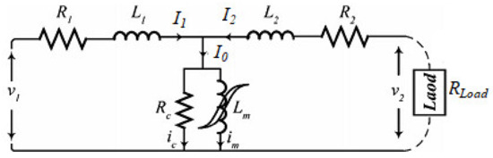
Figure 1.
Single-phase transformer equivalent circuit under steady-state conditions.
By applying Kirchhoff’s current law (KCL) at the single node of the circuit shown in Figure 1,
By applying Kirchhoff’s voltage law (KVL), the loop equations are applied at the input side and output side of the equivalent circuit of the transformer,
where λ1 = λl1 + λm and λ2 = λl2 + λm. We know that L1 and L2 are considered linear inductances; the flux linkages of L1 and L2 can be written as λl1 = L1I1 and λl2 = L2I2. Therefore, I1 and I2 are given as
Applying the KVL in the middle loop of the above circuit is given as:
Substituting Equation (4) in Equation (2), the first state-space equation is achieved, which is
(First state-space equation)
Substituting Equation (5) in Equation (3), and considering V2 = −RLI2, the second state-space equation is modified as
(Second state-space equation)
Considering [1,4,5,6], the third state-space equation, which associates the nonlinear nature of the transformer magnetic core, is given by
(Third state-space equation)
To predict the current in the primary side winding with the EKF method, the nonlinear state-space model output is derived as:
Equations (7)–(10) give the state-space formulation of the nonlinear model of the transformer. In Equation (9), the inrush current im is not determined. Therefore, it is required to determine a nonlinear model of transformer, im=g (λm), in which g describes the nonlinear nature of the hysteresis andmagnetic saturation of the core.
According to the literature [10], various approaches are suggested for modeling this nonlinear behavior such as tangent, polynomial, and hyperbolic tangent functions, etc. Based on a trial and error approach, it was concluded that the combination of two Gaussian functions will best describe the nonlinear behavior of the 1-phase transformer that is studied in this paper. The criterion for assessment of the different models is the root mean square of the error (RMSE). The Gaussian model is given as:
According to the literature [10], the main coefficients of the Gaussian model are estimated by using nonlinear LS (NLS) optimization and the Levenberg-Marquardt algorithm technique. Different Gaussian functions are used to predict the magnetization curve of a transformer, as presented in Table 1 [10].

Table 1.
Different functions used for the estimation of the magnetization curve of the transformer.
Functions I, II, and III of the above Table 1 are used for various estimations of the magnetization curve, i.e., magnetizing current vs. magnetization and transformer inrush currents, as shown in Figure 2a,b, respectively [10]. The magnetic inrush currents are provided based on the various functions presented in the above Table 1 and it shows the behavior of the magnetic core [10].
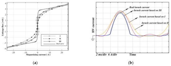
Figure 2.
Various estimated magnetization curves (a) with their respective inrush currents (b).
Different functions from Table 1 are used for modelling the magnetic core behavior of the transformer. Different estimations of the magnetization curve are compared in Figure 2a. Moreover, with different fulfilled estimations, the expected waveforms relevant to the transformer inrush current under various conditions are shown in Figure 2b.
3. EKF Formulation and Its Working Principle
The proposed working principle of EKF algorithm is given below.
3.1. Proposed Working Principle of the EKF
According to the literature [10], the nonlinear state-space model’s equation of the 1-phase transformer considered was derived in the previous section. The transformer primary side winding current using EKF is estimated for the model considered [10]. If the transformer is under a fault condition, the EKF will accurately predict the input current. If the considered transformer is in a faulty period, the model would not give proper nonlinear behavior due to the existing internal faults. Therefore, the estimation error of the EKF is increased, which depends on the accuracy of the model. In this regard, the estimation error is accountably large during the incipient cycles. Therefore, the absolute residual signal (ARS), i.e., the difference between the estimated and measured primary side currents, is increased at the incipient cycle while energizing a transformer in a faulty condition. This feature is used for the classification of transformer inrush currents from internal faults. Therefore, the ARS compares with the predefined threshold value for confirming or rejecting the protection systems [10].
3.2. Formation of the EKF
The nonlinear behavior of the state-space model can be given as follows:
where v and ω are uncorrelated white noises with zero mean and λ3×1 is the state vector. The complete algorithm of the proposed EKF is given by the following flowchart in Figure 3 [10].
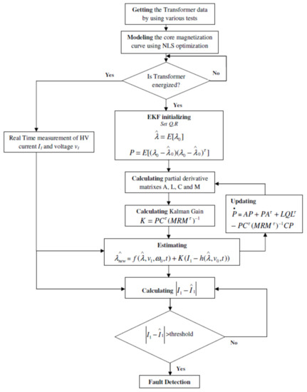
Figure 3.
Flowchart of the proposed EKF method for estimation of different fault currents.
The nonlinear vectors of Equation (12) for the transformer modeled in earlier sections are formulated in Equation (13).
In Equation (13), y and v1 are the measured magnetic inrush currents of the transformer and input voltage of each sample datum, respectively. Moreover, Q and R matrices are considered as
The Q and R matrices were chosen based on the present model and measurement uncertainties, and the matrices A, L, C, and M were also obtained, as given in Equations (14)–(17).
3.3. Operating Criteria
The residual signal instantaneous magnitude value is determined to bethe criterionfor differentiating fault currents of the transformer. The residual signal can be shown as:
where y and are the measured value (from the current transformer) and estimated (with EKF) currents, respectively. If the ARS is greater than the threshold value, the fault condition is discriminated. The selection of the threshold value is very important, because it may affect the operating time of estimation and accuracy percentage of the algorithm.
4. Analysis of Simulation Results of Transformer under Various Faults
The proposed method was implemented by using simulated data of the transformer to distinguish the different inrush and fault conditions. The inrush current may be present in the system when the transformer is energized under no-load or lightly loaded conditions. The equivalent circuit of the respective transformer under such conditions is shown in Figure 4. Consider Rs, Rp, and Rt are a series, core losses and source resistances and Ls and Lm are series and magnetizing inductances, respectively.
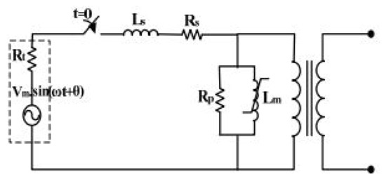
Figure 4.
Transformer equivalent circuit under the no-load condition.
4.1. Transformer Parameters
The single-phase transformer equivalent model was designed and simulated using MATLAB/Simulink, 2018a version by MathWorks, Natick, USA for different internal fault conditions and inrush currents conditions.
The transformer’s parameters are tabulated in Table 2.
Table 2.
Specifications of the single-phase transformer.
4.2. Types of Inrush Currents, Modeling, and Simulation of Inrush Currents
- Inrush current energization
- Recovery inrush current
- Sympathetic inrush current
4.2.1. Factors Affecting Inrush Currents
The inrush phenomenon occurs due to over-fluxing of the transformer core for a temporary period. This phenomenon may depend on:
- The switching time of the voltage waveform, when the transformer is energized.
- The magnitude and polarity of the flux (residual) persisting in the transformer at the re-energization time.
- Resistance on the primary side winding.
4.2.2. Effects of Switching Angle
The phase angle of starting voltage depends on the transformer when it is switched on. Therefore, the flux in the core also starts from zero at the time of switching. As per Faraday’s law of electromagnetic induction, the voltage induced across the winding is given as , where is the flux in the core. Hence, the flux is the integral of the voltage wave, which can be determined and it is shown in Figure 5 [3].
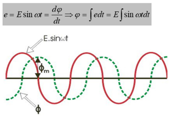
Figure 5.
Calculation of the induced emf.
The saturation of the transformer starts when it is crossed above the steady-state value of the flux, i.e., when the transformer is switching, the maximum value of flux will double the steady-state maximum value. After the occurrence of the steady-state maximum value of flux, the core becomes saturated and the respective current required for producing the rest of flux when it is high is shown in Figure 6 [3]. Let be the maximum value of the steady-state flux. In this regard, the transformer primary side will draw a high peak current from the source side. This phenomenon is treated as the inrush current or magnetizing inrush current of the transformer.
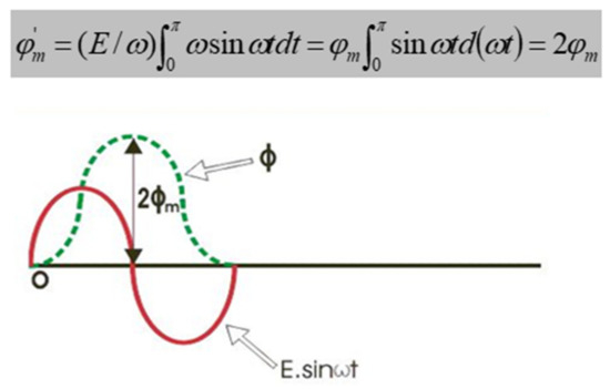
Figure 6.
Transformer flux doubling effect.
During the voltage switching at 90˚, the produced flux is the minimum and hence the current drawn. If the switching angle increases, it leads to a decrease in the amplitude of inrush current, which is shown in Figure 7 [3]. The representation of inrush current energization is shown in Figure 8, and inrush currents for various switching angles are shown in Figure 9.

Figure 7.
Variation in switching angle effects on inrush current amplitude.
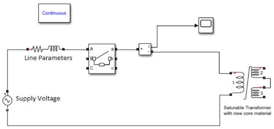
Figure 8.
Representation of energization inrush current.
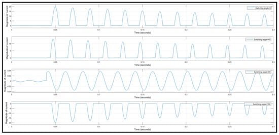
Figure 9.
Inrush currents for various switching angles.
The magnitudes of magnetic inrush currents for various switching angles are given in Table 3.
Table 3.
Magnitudes of magnetic inrush current for various switching angles.
Hence, the highest inrush current magnitude is treated for a zero-degree switching angle and the least inrush current magnitude is treated for a 90-degree switching angle. It is observed that increasing the switching angle decreases the amplitude of inrush current for different materials, as shown in Figure 10 and Figure 11.
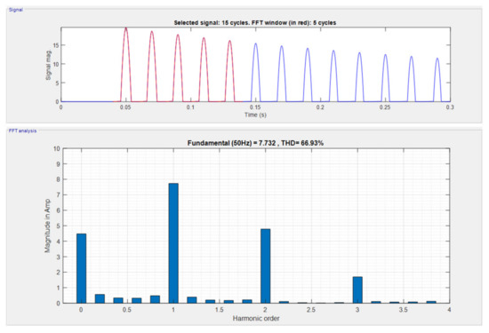
Figure 10.
Analysis of inrush current using FFT for old materials.
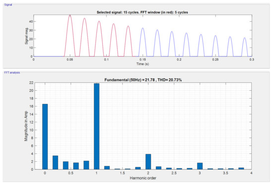
Figure 11.
Analysis of inrush currents using FFT for new materials (metglass).
Table 4 shows the magnitude of harmonic currents for old metals and new metals (metglass) of transformer core.
Table 4.
Magnitudes of harmonic currents for different metals of the transformer.
4.3. Modeling and Simulation of Internal Faults
The generation of internal faults, i.e., transformer internal turn faults along with current waveforms, is shown in Figure 12 and Figure 13, respectively.
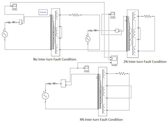
Figure 12.
Simulink model for various transformer internal (turn-to-turn) faults (no fault, 2% fault and 4% fault).
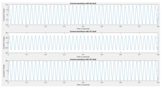
Figure 13.
Internal faults with energization for different percentages of winding shorted.
Table 5 shows the magnitude of internal fault current for different conditions of the transformer.
Table 5.
Magnitudes of internal fault currents for different cases.
4.4. Implementation of the EKF for the Specified Transformer
The simulation of transformer with the EKF for primary current estimation with the specific data of the transformer is shown in Figure 14.
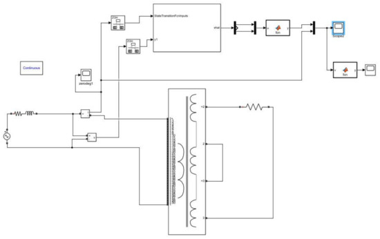
Figure 14.
Simulink model of the EKF for primary current estimation.
The functions used in the EKF block are:
dt = 0.0001; ind1 = 0.012256; ind2 = 0.000106; R1 = 2.59; R2 = 2 × 4.6344e-05; RC = 105,000; x = x + [(-R1×x(1)/ind1) + (R1× x(3)/ind1) + v; (-R2× x(2)/ind2) + (R2× x(3)/ind2);RC× x(1)/ind1 + RC× x(2)/ind2 − (RC× x(3)) ×(1/ind1 + 1/ind2)-RC× sign(x(3)) ×(13.89× exp(-((abs(x(3))-6.17)/2.58)^2)) − RC× sign(x(3)) ×(54.55× exp(-((abs(x(3))-6)/1.92)^2))] × dt; end
ind1 = 0.012256; ind2 = 2 × 5.55368e-5; R1 = 2.59; R2 = 2 × 4.6344e-05; RC = 105,000; y = (1/ind1) × x(1) − (1/ind1) × x(3); end |
4.5. Simulation Results of EKF Algorithm for Various Conditions
When the transformer is energized in various healthy conditions, the transformer is able to estimate it almost perfectly with a low residual signal value. The various estimated magnetization curves with their respective inrush currents mentioned in Section 2 are more useful for analysis of the EKF algorithm for estimation of inrush current [10].
The transformer is now energized after it has a 2% inter-turn fault. The combination of inrush and fault currents is not perfectly estimated by the EKF algorithm with a residue larger than in Figure 15; it can be observed in a close-up view of the EKF estimation during the inrush case in Figure 16. Similarly, the EKF was tested over the algorithms with various fault conditions; again, a high residual signal was generated, as shown in Figure 17 and Figure 18.
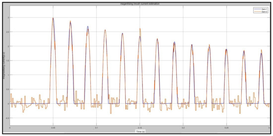
Figure 15.
Estimation of inrush current by EKF algorithm (blue line is actual current and red line is the EKF estimation current).
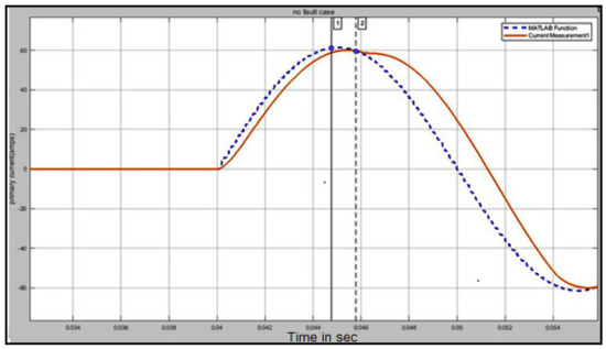
Figure 16.
Close up view of EKF estimation during inrush case (red line depicts actual current where the blue line is the estimated current waveform).
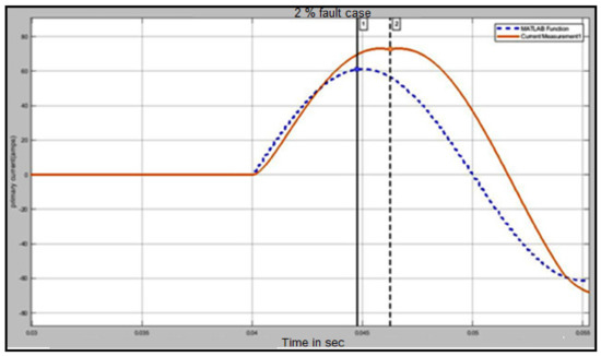
Figure 17.
EKF estimation during energization with a 2% internal fault.
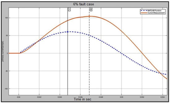
Figure 18.
EKF estimation during energization with a 6% internal fault.
The simulation model for discrimination of magnetic inrush current, 2% internal fault, 4% internal fault, and 6% internal fault along with current waveforms is given in Figure 19a,b and the respective ARS signals obtained from various sources are depicted in Figure 20, which indicates that the residual signal keeps increasing with the severity of the fault.
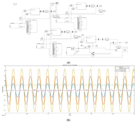
Figure 19.
(a) Simulation model with various types of internal faults. (b) ARS signals of magnetic inrush current along with fault current waveforms.
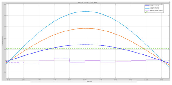
Figure 20.
ARS signals for various cases.
The Table 6 indicates the fault detection time with respect to the severity of the faults along with ARS signal amplitudes for different cases.
Table 6.
ARS signals and the fault detection time for various cases.
4.6. Observations
- The EKF algorithm was simulated for cases of inrush current with various switching angle cases, and the residue signal was found to be low and within limits (less than the selected threshold value in all cases).
- The internal fault current could not be estimated by the EKF filter and all the ARS values were found to be greater than the selected threshold value of 11 amperes (all fault conditions had an ARS of 11A or more, so this was selected as the threshold). If ARS > 11A, it is an internal fault; otherwise, it is not.
- While we prefer a shorter operating time, some fault cases may be perceived as inrush because the ARS value might not have crossed the threshold by then. Nevertheless, the operating point was always low (max 116 milliseconds, which is much less than a cycle). As the severity of the fault increases, the detection time decreases as the required residual threshold is achieved earlier.
- EKF is independent of the low second harmonic problem as the filter takes into account the BH curve of the core. If the core material or other parameters of the transformers are changed, the equations for the EKF algorithm will have to be changed as well and, hence, the algorithm is able to predict the inrush currents in every case provided the equations are derived and implemented carefully.
- The state-space model and all the coefficients must be derived very carefully. Even a slight mistake can cause the EKF to diverge, which is bound to give the wrong output.
5. Conclusions
In this paper, the EKF was implemented for the discrimination of inrush currents and internal faults current of a single-phase transformer. The state-space equations of the power transformer were simplified using simple circuit theory and curve fitting (for saturation curve). By using the two-step predictive-corrective mechanism of the EKF algorithm, the estimation of the primary winding current of the transformer was achieved. The transformer primary winding current was estimated for various switching angles and faults using the EKF. It was observed that the ARS value is zero under normal conditions, and it will not be equal to zero for internal fault and inrush phenomena conditions. Hence, the EKF algorithm was implemented for discriminating the internal faults and inrush faults by keeping the threshold level at the ARS value. The simulation results were validated with the theoretical analysis under various fault conditions. It is also concluded that the detection time of internal faults decreases with the severity of the fault. Hence, this scheme provides fast protection of the transformer for severe faults. The results of various test cases using the EKF algorithm were presented. The implementation of the EKF can be extended to protect other power system equipments for classification of faults.
Author Contributions
Conceptualization, S.K.G. and V.S.S.S.S.D.; data curation, S.K.G.; formal analysis, S.K.G.; methodology, S.K.G. and V.S.S.S.S.D.; supervision, V.S.S.S.S.D.; writing—original draft, S.K.G. and V.S.S.S.S.D.; writing—review and editing, S.K.G. and V.S.S.S.S.D. Both authors have read and agreed to the published version of the manuscript.
Funding
This research received no external funding.
Institutional Review Board Statement
Not applicable.
Informed Consent Statement
Not applicable.
Acknowledgments
The authors gratefully acknowledge the Department of Electrical Engineering of the National Institute of Technology, Warangal for their support.
Conflicts of Interest
The authors declare no conflict of interest.
References
- Zheng, T.; Yang, X.; Guo, X.; Wang, X.; Zhang, C. Zero-Sequence Differential Current Protection Scheme for Converter Transformer Based on Waveform Correlation Analysis. Energies 2020, 13, 1814. [Google Scholar] [CrossRef] [Green Version]
- Shahabodin, A.; Mousa, A.; Benyamin, P.; Mohammad, M. Integration of Accelerated Deep Neural Network into Power Transformer Differential Protection. IEEE Trans. Ind. Inform. 2020, 16, 865–876. [Google Scholar]
- Gopika, R.; Deepa, S. Study on Power Transformer Inrush Current. IOSR J. Electr. Electron. Eng. 2017, 2, 59–63. [Google Scholar]
- Hassan, A.; Majid, S. A novel technique for internal fault detection of power transformers based on moving windows. Int. Trans.Electr. Energy Syst. 2014, 24, 1263–1278. [Google Scholar]
- Luliang, Z.; Mengshi, L.; Tianyao, J.; Jie, Z. Identifying magnetizing inrush in power transformers based on symmetry of current waveforms. IEEJ Trans. Electr. Electron. Eng. 2017, 12, 959–960. [Google Scholar]
- Bahador, F.; Golshan, M.; Abyaneh, H.; Saghaian-Nejad, M. A runs test-based method for discrimination between internal faults and inrush currents in power transformers. Eur. Trans. Electr. Power 2011, 21, 1392–1408. [Google Scholar]
- Zhang, H.; Wen, J.; Liu, P.; Malik, O. Discrimination between fault and magnetizing inrush current in transformers using short-time correlation transform. Electr. Power Energy Syst. 2002, 24, 557–562. [Google Scholar] [CrossRef]
- Youssef, O. A Wavelet-Based Technique for Discrimination between Faults and Magnetizing Inrush Currents in Transformers. IEEE Trans. Power Deliv. 2003, 18, 170–176. [Google Scholar] [CrossRef]
- Hajipour, E.; Vakilian, M.; Majid, S. Current-Transformer Saturation Compensation for Transformer Differential Relays. IEEE Trans. Power Deliv. 2015, 30, 2293–2302. [Google Scholar] [CrossRef]
- Naseri, F.; Kazemi, Z.; Arefi, M.; Farjah, E. Fast Discrimination of Transformer Magnetizing Current from Internal Faults: An Extended Kalman Filter-Based Approach. IEEE Trans. Power Deliv. 2018, 33, 110–118. [Google Scholar] [CrossRef]
- Ma, J.; Wang, Z.; Yang, Q.; Liu, Y. A Two Terminal Network-Based Method for Discrimination between Internal Faults and Inrush Currents. IEEE Trans. Power Deliv. 2010, 25, 1599–1605. [Google Scholar] [CrossRef]
- Sahebi, A.; Samet, H. Discrimination between internal fault and magnetising inrush currents of power transformers in the presence of a superconducting fault current limiter applied to the neutral point. IET Sci. Meas. Technol. 2016, 10, 537–544. [Google Scholar] [CrossRef]
- Bagheri, S.; Moravej, Z.; Gharehpetian, G. Classification and Discrimination among Winding Mechanical Defects, Internal and External Electrical Faults, and Inrush Current of Transformer. IEEE Trans. Ind. Inform. 2018, 14, 484–493. [Google Scholar] [CrossRef]
- Faiz, J.; Lotfi-Fard, S. A Novel Wavelet-Based Algorithm for Discrimination of Internal Faults from Magnetizing Inrush Currents in Power Transformers. IEEE Trans. Power Deliv. 2006, 21, 1989–1996. [Google Scholar] [CrossRef]
- Eissa, M. A Novel Digital Directional Transformer Protection Technique Based on Wavelet Packet. IEEE Trans. Power Deliv. 2005, 20, 1830–1836. [Google Scholar] [CrossRef]
- Ahmadi, M.; Samet, H.; Ghanbari, T. Discrimination of internal fault from magnetizing inrush current in power transformers based on sine-wave least-squares curve fitting method. IET Sci. Meas. Technol. 2014, 9, 73–84. [Google Scholar] [CrossRef]
- Hongtian, C.; Bin, J. A Review of Fault Detection and Diagnosis for the Traction System in High-Speed Trains. IEEE Trans. Intell. Transp. Syst. 2020, 21, 450–465. [Google Scholar]
- Chao, C.; Wang, W.; Chen, H.; Zhang, B.; Shao, J.; Teng, W. Enhanced Fault Diagnosis Using Broad Learning for Traction Systems in High-Speed Trains. IEEE Trans. Power Electron. 2021, 36, 7461–7469. [Google Scholar]
- Thote, P.; Daigavane, M.; Daigavane, P.; Gawande, S. An Intelligent Hybrid Approach Using KNN-GA to Enhance the Performance of Digital Protection Transformer Scheme. Can. J. Electr. Comput. Eng. 2017, 40, 151–161. [Google Scholar]
- Batista, Y.; Souza, H.; Santos Neves, F.; Dias Filho, R. A GDSC-Based Technique to Distinguish Transformer Magnetizing from Fault Currents. IEEE Trans. Power Deliv. 2018, 33, 589–599. [Google Scholar] [CrossRef]
- Li, C.; Zhou, N.; Liao, J.; Wang, Q. Multiscale multivariate fuzzy entropy-based technique to distinguish transformer magnetising from fault currents. IET Gener. Transm. Distrib. 2019, 13, 2319–2327. [Google Scholar] [CrossRef]
- Shah, A.; Bhalja, B. Fault discrimination scheme for power transformer using random forest technique. IET Gener. Transm. Distrib. 2016, 10, 1431–1439. [Google Scholar] [CrossRef]
Publisher’s Note: MDPI stays neutral with regard to jurisdictional claims in published maps and institutional affiliations. |
© 2021 by the authors. Licensee MDPI, Basel, Switzerland. This article is an open access article distributed under the terms and conditions of the Creative Commons Attribution (CC BY) license (https://creativecommons.org/licenses/by/4.0/).