Abstract
The traditional model predictive control (tMPC) algorithms have a large amount of online calculation, which makes it difficult to apply them directly to turboshaft engine–rotor systems because of real time requirements. Therefore, based on the theory of the perturbed piecewise affine system (PWA) and multi-parameter quadratic programming explicit model predictive control (mpQP-eMPC) algorithm, we develop a controller design method for turboshaft engine–rotor systems, which can be used for engine steady-state, transient state and limit protection control. This method consists of two steps: controller offline design and online implementation. Firstly, the parameter space of the PWA system is divided into several partitions offline based on the disturbance and performance constraints. Each partition has its own control law, which is in the form of piecewise affine linear function between the controller and the parameters. The control laws for those partitions are also obtained in this offline step. After which, for the online control implementation step, the corresponding control law can be obtained by a real-time query of a corresponding partition, which the current engine state falls into. This greatly reduces the amount of online calculation and thus improves the real-time performance of the MPC controller. The effectiveness of the proposed method is verified by simulating the steady-state and transient process of a turboshaft engine–rotor system with a limit protection requirement. Compared with tMPC, an mpQP-eMPC based controller can not only guarantee good steady-state, dynamic control performance and limit protection, but can also significantly improve the real-time performance of the control system.
1. Introduction
Helicopters play an important role in short distance transportation, aerial photography, agriculture, disaster search and rescue and other fields. The power unit of a helicopter is important and the turboshaft engine is the main selection for most helicopters in the world because of its high power-to-weight ratio and low vibration. Therefore, improving the reliability and advancement of the turboshaft engine control system is the key to improving the overall maneuverability of the helicopter to meet the needs of modern industry, agriculture and military [1]. Since the dynamics of the propeller rotor and the engine are coupled through the gear transmission system, the working state of the turboshaft engine will be affected by the propeller rotor load with large inertia. The low dynamic characteristic of a high inertia rotor load creates a great challenge for the design of a high performance control system.
The difficulties in the design of turboshaft engine control systems are mainly reflected in two aspects. First, the turboshaft engine and the rotor system are directly connected through physical structures, such as gearboxes and driven shafts, which makes a strong dynamics coupling between the two independent systems. Currently, for most turboshaft engines, a traditional PID linear controller with MAX–MIN high–low selection logic structure is widely used. However, for this nonlinear dynamic system with strong coupling dynamics and strong constraints, the performance of this kind of controller is unsatisfying. The acceleration and deceleration transition is slow, and the overshoot and droop can reach 4%, which causes great damage to the engine’s life span and safety [2]. Therefore, the traditional PID controller has been unable to meet the performance requirements of modern high-performance turboshaft engines due to its limitations. The research on new control algorithms to adapt to the rapid development of turboshaft engines has become of great interest to controller designers. Thanks to the development of MPC methods, research on MPC methods for turboshaft engine control has been attractive to the engineering community.
MPC originated in the 1970s. Due to its unique advantages, such as the ability to predict future output, process constrained optimization, and the ability to suppress un-modeled dynamic error and environmental disturbance uncertainty, it has been widely discussed by the industry [3,4,5], and has been successfully applied in industrial process control with slow dynamic characteristics such as petroleum smelting and chemical industry [6,7,8]. Currently, all the application research of turboshaft engines that we can find is particularly scarce and most of the model predictive controller designs for aeroengines are focused on solving the model mismatch phenomenon. At the present time, the real-time research on model predictive controllers for turboshafts is limited. However, in the face of the complex nonlinear dynamic system of turboshaft engines with strong rotor coupled dynamics and strong constraint conditions, and due to the huge amount of calculation in the optimization process, it is difficult to apply in real-time and online engineering, and its development has thus been limited in recent years. In summary, since there are few model predictive real-time controller designs of turboshaft engines and the real-time performance is of great importance for engines, mpQP-eMPC real-time research is carried out in this paper.
In order to solve the problem introduced by the large number of online calculations of tMPC, Bemporad proposed the mpQP-eMPC algorithm based on multi-parameter quadratic programming theory in [9]. Parametric programming is a kind of optimization problem with parameters; multi-parameter quadratic programming is popular in academia because of its convexity [10,11]. Due to the partition of the parameter space, the multi-parameter quadratic programming has the ability to obtain the explicit controller offline, which can simplify the process of the online solution [12,13,14]. The mpQP-eMPC based on parametric quadratic programming can reduce the online computing time to meet the real-time requirements. Considering the high real-time requirements of a turboshaft engine rotor system’s control system, this paper will design a turboshaft engine controller based on mpQP-eMPC to solve the problem of tMPC being unable to guarantee real-time performance.
Based on the perturbed PWA model of turboshaft engine rotor systems, through theoretical derivation, this paper transforms the control problem of turboshaft engines into a standard mpQP-eMPC controller design problem. The specific solution of the affine function relationship is also derived. The control design process of turboshaft engines proposed in this paper is described as follows: Firstly, the parameter space is reasonably partitioned. By way of the derivation introduced in this paper, the detailed piecewise affine linear function relationship between the controller and the related parameters on each parameter partition is obtained. These are all conducted in the offline step. Then, during online implementation, the optimal control decision of the turboshaft engine–rotor system is obtained by querying the partition of the system state. The simulation results show that mpQP-eMPC is better than tMPC in ensuring the steady-state and transient dynamic performance of the turboshaft engine rotor system, and the average calculation time of mpQP-eMPC is 0.002 times that of tMPC, which can meet the real-time requirements.
The rest of the paper is organized as follows: Section 2 briefly introduces the turboshaft engine–rotor system and its perturbed PWA model. Section 3 presents the mpQP-eMPC algorithm for the turboshaft engine–rotor system. In Section 4, a simulation study on a turboshaft engine–rotor system is presented to verify the proposed method. Finally, Section 5 concludes the paper.
2. Turboshaft Engine–Rotor System and Its Perturbed PWA Model
The turboshaft engine–rotor system is shown in Figure 1 and its main control objective is to keep constant power turbine rotation speed by quickly adjusting the gas turbine rotation speed through changing the input fuel flow when the collective pitch changes under different flight tasks. This is necessary to meet the requirements of the rotor load changes of the helicopter. The controller should ensure that the acceleration and deceleration time is as short as possible during the transition state, and the key performance parameters of the engine are within the limits in the meantime.
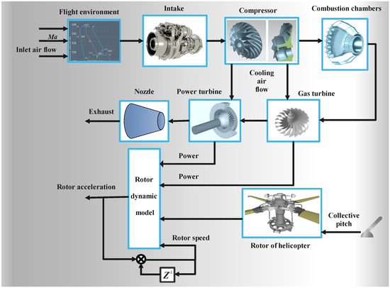
Figure 1.
The structure diagram of the turboshaft engine–rotor system.
The state space nonlinear equations of the turboshaft engine–rotor system are described as follows:
where are the state variables of the system, is the rotation speed of the gas turbine, is the rotation speed of the power turbine, is the fuel input of the turboshaft engine, and the disturbance input is the collective pitch input of the rotor system, the flight altitude is H and the flight Mach number is .
Equation (1) only highlights the input and output parameters without providing the explicit relationship between them. In fact, we cannot build this explicit input–output function expression of the engine. Therefore, for the requirements of controller design, the construction work of the PWA system is carried out based on the component-level model shown in Figure 1.
Since the dynamic process of the turboshaft engine–rotor system (shown in Figure 1) and Equation (1) is highly nonlinear and has strong coupling characteristics, the controller design is completed by considering the PWA modeling method. Firstly, the nonlinear state space model of the turboshaft engine–rotor system is linearized in the ground state (, ). At s steady-state working points, the discrete turboshaft engine rotor-system PWA model is established:
where , , , i represents the ith linear system. High altitude and other flight conditions can be transformed into ground states by similarity theory, so as to realize the full flight envelope control of the engine.
Remark 1.
Through a lot of simulation research and a contrast between the PWA and the turboshaft engine results, the final value of s is determined with . The matching between the two when will be proven in Section 4.1.
3. mpQP-eMPC Algorithm for Turboshaft Engine–Rotor System
The mpQP-eMPC structure of the turboshaft engine–rotor system is shown in Figure 2. The design process can be divided into two steps:
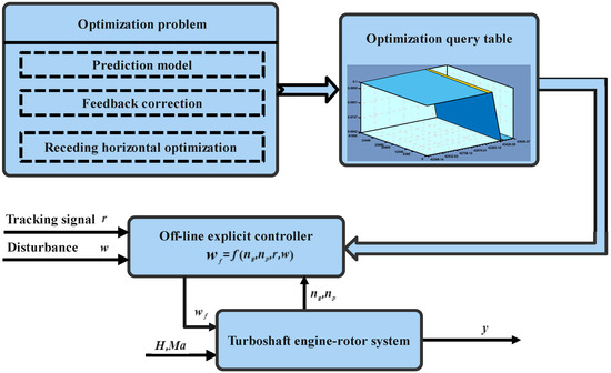
Figure 2.
The structure diagram of mpQP-eMPC.
- The tMPC optimization problem of the turboshaft engine–rotor system is transformed into a standard mpQP-eMPC problem;
- The turboshaft engine controller design based on mpQP-eMPC.
3.1. Standard mpQP-eMPC Algorithm
Firstly, the standard description of mpQP-eMPC with parameter is shown as follows:
where Z is the optimization variable and is the optimization parameter. Matrices H, G and W are the weight matrix of objective function and constraints matrices, respectively. One of the objectives in this paper is to convert the parameters in Equation (2) and the classical MPC control into the standard mpQP-eMPC problem in Equation (3).
The mpQP-eMPC explicit solution is based on the concepts of polytopic partition and piecewise affine function.
Definition 1
([10]). If a polyhedron set and a polyhedron ϑ satisfy the following conditions, then the polyhedron set is a polyhedron partition of polyhedron ϑ:
Definition 2
([10]). Consider the function , , if there is always a polyhedral partition of the set ϑ, , such that , , then the function f is said to be piecewise affine.
Based on Definitions 1 and 2 and Lemma 1, the explicit optimal solution of (3) can be obtained.
Lemma 1
([9]). Based on the multi-parameter programming method to solve the optimization problems (3), then its feasible region is convex and the optimal solution is continuous and piecewise affine:
Lemma 1 serves as a tool to obtain the explicit expression of the mpQP-eMPC controller for the turboshaft engine–rotor and will be used in the rest of this article.
3.2. Transformation of Turboshaft Engine Controller and mpQP-eMPC Controller
The traditional tMPC control algorithm of the turboshaft engine is described as follows:
In order to transform the tMPC of the turboshaft engine into the standard mpQP-eMPC form, the state prediction equation and output prediction equation of the perturbed PWA system are calculated based on (2).
State prediction equation:
Output prediction equation:
where
The parameter constraints conditions of Equation (6) are equivalent to:
Let
then:
Remark 2.
The transformation is necessary. The benefit from the standard form of mpQP-eMPC, the deducing procedure of explicit expression in solving the optimization problem based on KKT conditions becomes simpler, more concise and easier to understand.
3.3. Offline Solution Algorithm of Turboshaft Engine Controller Based on mpQP-eMPC
The transformation of the turboshaft engine–rotor system tMPC into the standard mpQP-eMPC optimization problem is completed as above, and the turboshaft engine controller offline step can now proceed by referring to the mpQP-eMPC algorithm procedure.
Lemma 2
([15]). For any partition of the parameter space ϑ, suppose that the optimization problem (13) on satisfies both the linear independent constraint condition LICQ and the strict complementary relaxation condition, and (13) has an initial feasible solution in ϑ, then the optimal solution of the optimization problem (13) is as follows:
where , , , , and represent the ith row of matrix G, S, and W respectively. Y is a zero matrix of dimension , is a set of nonnegative Lagrange multipliers, is a set of initial feasible solutions of optimization problem (13).
From Lemma 2, it is not difficult to find that the key to solving the optimization problem is to determine a partition of and the feasible solutions and on any partition . The partition of can refer to the method in Lemma 3.
Lemma 3
([9]). Suppose is a polytope (polyhedron), is a subset of , and . Let , ,
then: is a partition of ϑ, where , ,
Next, the explicit expression of the mpQP-eMPC controller is given through the following theorem.
Theorem 1.
Assuming that the parameter space partition of the perturbed PWA system (2) is obtained based on the method in Lemma 3, where is the first m rows of matrix , is the first m rows of matrix , and m is the number of rows of Z, then the mpQP-eMPC controller of the turboshaft engine–rotor system is continuous, and its explicit expression on any partition is as follows:
Proof.
From Lemma 1, we can see that the mpQP-eMPC controller of the turboshaft engine–rotor system is continuous. Based on Lemma 2, . Because , therefore:
Thus, Theorem 1 is proved. □
Furthermore, with the help of Chebyshev distance, a feasible solution of the optimization problem (13) in any partition is obtained:
If , then the problem in (13) is infeasible for all in . Otherwise, we fix and obtain based on the following standard quadratic optimization problem:
Finally, based on Lemmas 2 and 3, solutions and of Equations (17) and (18), and Theorem 1, the mpQP-eMPC controller algorithm of the turboshaft engine rotor system is summarized in Algorithm 1.
| Algorithm 1 mpQP-eMPC Controller Iteration Algorithm |
| Step 1: In the space , based on the optimization problem (17), find the initial value of the parameter ; Step 2: Fix , and obtain by solving quadratic programming optimization problem Equation (18); Step 3: Determine the critical region near the equilibrium point by judging whether is greater than 0; Step 4: Based on Equation (16) in Theorem 1. to obtain the expressions of and in the critical region ; Step 5: Divide the critical region based on Lemma 3 to obtain the subcritical region of this critical region; Step 6: Repeat the above steps to segment each subcritical domain iteratively, and determine the values of and in each polyhedron (polyhedron) based on Theorem 1. |
3.4. Analysis of the Influence of on the Partition Number of Parameter Space
The length of the prediction horizon has a direct impact on the number of parameter space partitions. In general, the larger the , the more parameter space partitions, and the longer the time it takes to find the controller during the online query procedure. However, the length of is not the bigger the better. The case of in the turboshaft engine is taken as an example to illustrate this argument.
The linear system at (corresponding to the linear system with in (1)) is considered:
Note that matrices A, B, C and w are the results of normalization and discretizing.
For and , respectively, based on the iterative algorithm summarized in Table 1, the explicit model predictive controllers are designed for the system (19) according to the given values in Table 1.

Table 1.
Simulation parameter table.
Among them, Figure 3 and Figure 4 are the simulation results when ; Figure 5 and Figure 6 show the simulation results when . It can be seen from Figure 3 and Figure 5 that, when , the system state space can be divided into five partitions, and when , the system state space can be divided into 33 partitions. That is to say, the larger the , the more divisions of the interval division. However, when , only the number of parameter space partition changes, and the controller value does not change greatly. In this case, the dynamic performance of the controlled plant is consistent with that of . Therefore, when the turboshaft engine rotor system is considered, the size of should be selected reasonably according to the dynamic of the system to reduce the online online controller query time.
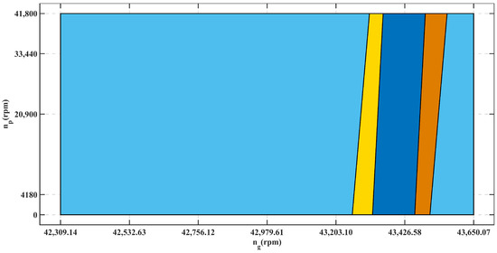
Figure 3.
The partition of state space: .
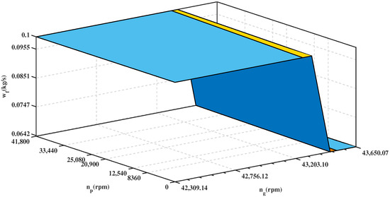
Figure 4.
Affine function relationship between controller and state partition: .
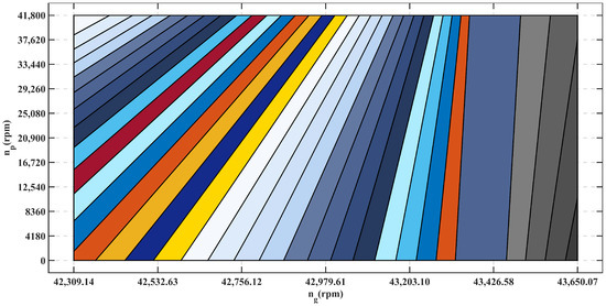
Figure 5.
The partition of state space: .
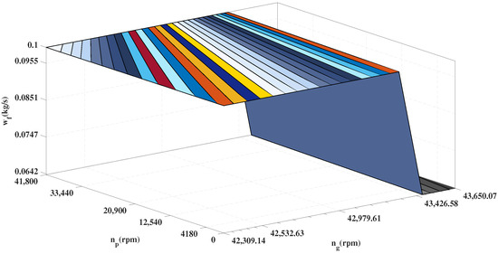
Figure 6.
Affine function relationship between controller and state partition: .
4. Simulation Example
Under flight condition , , ten equilibrium points are selected to establish the PWA system for the turboshaft engine–rotor component-level nonlinear model. Some of the PWA models are shown as follows; the others are similar.
Equilibrium point 1 (): ,
Equilibrium point 2 (): ,
Equilibrium point 6 (): ,
Equilibrium point 8 (): ,
Equilibrium point 10 (): ,
Note that all the matrices appearing in the (20)–(24) are the results of normalization and discretizing.
4.1. PWA System
Based on two groups of different input signals, the effectiveness of PWA system modeling is verified.
(1) Figure 7 shows the step input signal of the engine fuel and rotor system (including the large step signal in the first 250s and the small step signal in the last 950s). The speed response curves of PWA system and turboshaft engine–rotor system are shown in Figure 8 and Figure 9. Among them, the maximum overshoot of power turbine speed is 0.9569%, the steady-state modeling error is less than 0.024%. The transition and the steady-state modeling error of gas turbine rotaion speed are both less than 0.01%.
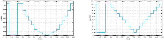
Figure 7.
Step input signals of fuel and collective pitch .
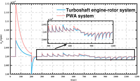
Figure 8.
Speed response curves of power turbine.
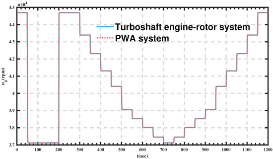
Figure 9.
Speed response curves of gas turbine.
(2) Figure 10 shows the ramp input signals of engine fuel and collective pitch of the rotor system. The speed response curves of the PWA system and the turboshaft engine–rotor system are shown in Figure 11 and Figure 12. According to the response curves of power turbine rotation speed and gas turbine rotation speed , the steady-state and dynamic errors of are less than 0.24%; The steady and dynamic error of is less than 0.01%. Therefore, the output of the PWA system is basically consistent with the nonlinear model of the turboshaft engine rotor system, which meets the requirements of the controller design.
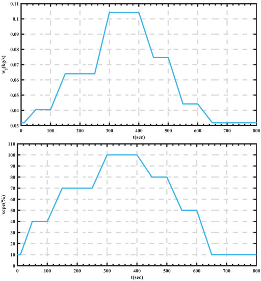
Figure 10.
Ramp input signals of fuel and collective pitch .
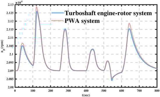
Figure 11.
Speed response curves of power turbine.
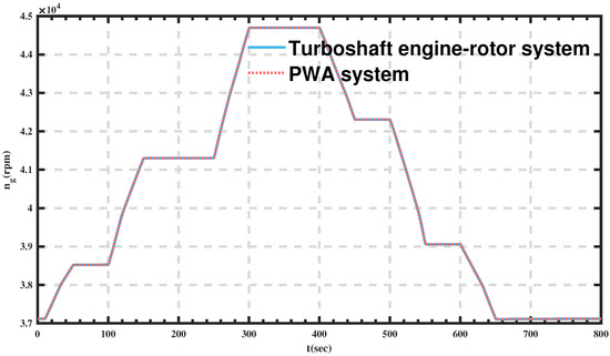
Figure 12.
Speed response curves of gas turbine.
4.2. mPQP-eMPC Controller
In the design process of the control system, by making , an integral unit is added to ensure the steady-state servo tracking without static error, and the fuel change rate limit is introduced into the optimization problem (13) to take into consideration actuator position saturation and rate saturation.
Based on the constraints and parameter settings in Table 2, the explicit model predictive controller is designed according to procedures proposed in the above contents and is compared with the tMPC method, where Q is and R is .
Table 2.
Simulation parameter table.
The input signal of collective pitch is designed to simulate vertical take off and landing procedure of the helicopeter (Figure 13): During the first 10 s, the collective pitch lever is pushed up quickly to make a rapid step change of value from 10% to 100%. The turboshaft engine will have to transfer from idle working state to maximum power state quickly. This is to simulate the vertical take-off process. After working on for approximately 100 s, the collective pitch lever is pulled down in two steps to make drop from 100% to 10% which realizes rapid vertical descent process. The helicopter vertical climbing process is also simulated: the collective pitch slowly increases from 10% position to 100% position step by step. The simulation results are shown in Figure 14, Figure 15, Figure 16 and Figure 17.
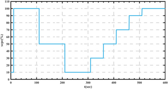
Figure 13.
The input signal of collective pitch.
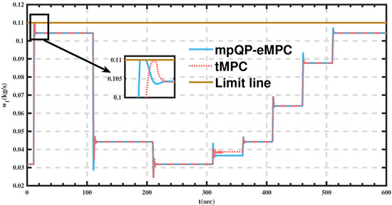
Figure 14.
The response curves of fuel .
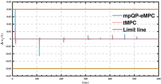
Figure 15.
The response curves of fuel rate .
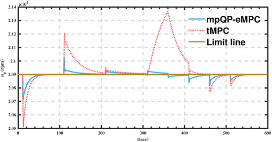
Figure 16.
Speed response curves of power turbine.
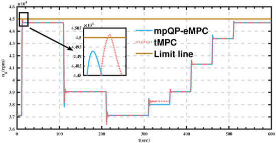
Figure 17.
Speed response curves of gas turbine.
Figure 14 shows the fuel flow response curves in two comparative algorithms. The controller based on the mpQP-eMPC algorithm proposed in this paper can ensure that the fuel flow reaches the limit line quickly without exceeding the limit. The fuel rate response curve is shown in Figure 15: the mpQP-eMPC based algorithm can ensure that the fuel rate is close to the limit line as soon as possible but keeps within the limited change rate range in the same time. The system dynamic response performance is thus improved. Figure 16 shows the speed response curve of gas turbine under two comparative algorithms: the mpQP-eMPC based method does not exceed the limited range for the rotation speed of gas turbine, while under the control of tMPC, the rotation speed of the gas turbine violates the speed constraint for a certain period of time. Figure 17 shows the rotation speed response curve of the power turbine under two comparative controllers: the power turbine rotation speed response under the mpQP-eMPC based controller is faster than that under the control of tMPC. The rotation speed overshoot under the mpQP-eMPC controller is also smaller whose maximum value is less than 1.44% compared to 2.4% under the control of tMPC. The steady-state control error is less than 0.005% with the controller proposed in this paper.
4.3. Real-Time Verification of Mpqp-Empc
In order to verify the real-time performance of the mpQP-eMPC control algorithm, based on a 3.4 GHz Intel processor, simulation verification is carried out considering the different length prediction time domain. The selection of is shown in Table 3. In addition, the sampling time is 0.01 (sec) for simulation setting, and the change of collective pitch is the same as shown above in Figure 13.
Table 3.
Real time verification table.
The comparison simulation results of the two methods are shown in Table 3, and the comparison simulation results are shown in Figure 18, Figure 19, Figure 20 and Figure 21.
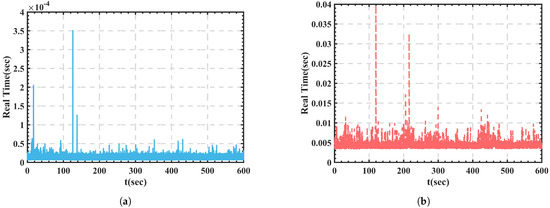
Figure 18.
When ny = 3, at each sampling time: (a) mpQP-eMPC calculation time; (b) tMPC calculation time.
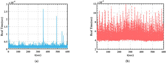
Figure 19.
When ny = 5, at each sampling time: (a) mpQP-eMPC calculation time; (b) tMPC calculation time.
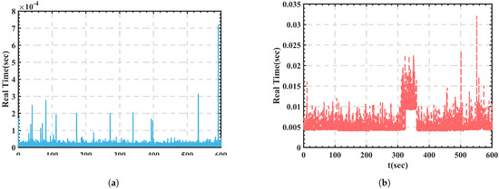
Figure 20.
When ny = 7, at each sampling time: (a) mpQP-eMPC calculation time; (b) tMPC calculation time.
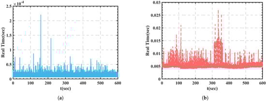
Figure 21.
When ny = 9, at each sampling time: (a) mpQP-eMPC calculation time; (b) tMPC calculation time.
Figure 18 shows the calculation time of different algorithms at each sampling time when . The average calculation time of the mpQP-eMPC controller is s, and the maximum calculation time is s; The average computing time of the traditional MPC controller is s, and the maximum computing time is s.
Figure 19 shows the calculation time of different algorithms at each sampling time when . The average calculation time of the mpQP-eMPC controller is s, and the maximum calculation time is s; the average computing time of the traditional MPC controller is s, and the maximum computing time is s.
Figure 20 shows the calculation time of different algorithms at each sampling time when . The average calculation time of the mpQP-eMPC controller is s, and the maximum calculation time is s; the average computing time of the traditional MPC controller is s, and the maximum computing time is s.
Figure 21 shows the calculation time of different algorithms in each sampling time when . The average calculation time of mpQP-eMPC controller is s, and the maximum calculation time is 2.1990 s; the average computing time of the traditional MPC controller is s, and the longest computing time is s.
Remark 3.
References [16,17] also offer different methods to improve the real-time property, such as Mehdi Hosseinzadeh using the explicit reference governor to enhance the real time character in [16]. Meanwhile, reference [17] has also done a lot of related work on this, and the method proposed in [17] can be seen as an extension of the method in [16]. In addition, there are some robust methods that can improve the real-time performance of the model predictive algorithm [4]. However, considering that inequality scaling is involved and the special research objects, such as turboshaft engines, have strict requirements on the performance of the control system, we have not tried these methods to improve the real-time performance. However, these methods are indeed worth trying, and this may be an important part of our work in the future.
5. Conclusions
A real-time explicit model prediction control for turboshaft engines based on multi-parameter quadratic programming is proposed. Firstly, the perturbed PWA system is constructed. Then, based on the theory of PWA and multi-parameter quadratic programming, the mpQP-eMPC controller is designed for turboshaft engine–rotor systems. Finally, the effectiveness of the proposed method is verified by simulating the steady-state and transient process of a turboshaft engine–rotor system with a limit protection requirement. The simulation result proves that: (1) the perturbed PWA linear modeling method is accurate enough; (2) under the proposed mpQP-eMPC based controller, the system dynamic performance is improved while obeying certain constraints at the same time; (3) it breaks through the bottleneck of tMPC finding it difficult to guarantee the real-time performance of turboshaft engines.
There are many ways to improve the real-time performance, but we just tried one of these methods on the turboshaft engine. The focus of future research can be to try a variety of methods to enhance the real-time performance of the MPC algorithm and to finally determine a method that can best improve the control performance of the turboshaft engine.
Author Contributions
Conceptualization, N.G.; methodology, N.G.; software, N.G.; validation, N.G.; formal analysis, N.G.; investigation, N.G.; resources, N.G.; data curation, N.G.; writing—original draft preparation, N.G.; writing—review and editing, X.W.; visualization, X.W.; supervision, X.W., N.G. and M.Z.; project administration, X.W.; funding acquisition, X.W. and X.W. All authors have read and agreed to the published version of the manuscript.
Funding
This work was supported by National Science and Technology Major Project under Grant 2017-V-0015-0067.
Institutional Review Board Statement
Not applicable.
Informed Consent Statement
Not applicable.
Data Availability Statement
The data presented in this study are available on request from the corresponding author.
Acknowledgments
The authors would like to thank the support from Collaborative Innovation Center for Advanced Aero-Engine.
Conflicts of Interest
The authors declare no conflict of interest.
Abbreviations
| Gas turbine rotation speed | |
| Gas turbine rotation speed at equilibrium point | |
| Power turbine rotation speed | |
| Power turbine rotation speed at equilibrium point | |
| Collective pitch input of rotor system | |
| Collective pitch input at equilibrium point | |
| Engine fuel input | |
| Engine fuel input at equilibrium point | |
| H | Helicopter flight altitude |
| Prediction horizon | |
| Helicopter flight Mach number | |
| Control horizon | |
| MPC | Model predictive control |
| tMPC | Traditional model predictive control |
| mpQP-eMPC | Multi-parameter quadratic programming explicit model predictive control |
| PWA | Piecewise affine system |
References
- Ballin, M.G. A High Fidelity Real-Time Simulation of a Small Turboshaft Engine; NASA Technical Memorandum; National Aeronautics and Space Administration: Washington, DC, USA, 1988.
- Rasmussen, H. Advanced Control of Turbofan Engines; Springer: New York, NY, USA, 2012. [Google Scholar]
- Mhaskar, P. Robust Model Predictive Control Design for Fault-Tolerant Control of Process Systems. Ind. Eng. Chem. Res. 2006, 45, 8565–8574. [Google Scholar] [CrossRef]
- Xia, Y.; Liu, G.P.; Shi, P.; Chen, J.; Rees, D. Robust constrained model predictive control based on parameter-dependent Lyapunov functions. Circuits Syst. Signal Process. 2008, 27, 429–446. [Google Scholar] [CrossRef] [Green Version]
- Wang, T.; Gao, H.; Qiu, J. A Combined Adaptive Neural Network and Nonlinear Model Predictive Control for Multirate Networked Industrial Process Control. IEEE Trans. Neural Netw. Learn. Syst. 2017, 27, 416–425. [Google Scholar] [CrossRef] [PubMed]
- Luo, X.; Yang, Y.U.; Jun, X.U.; Automation, D.O. Online optimization implementation on model predictive control in chemical process. Ciesc J. 2014, 65, 3984–3992. [Google Scholar]
- Tyagunov, A.A. High-Performance Model Predictive Control for Process Industry. Ph.D. Thesis, Technische Universiteit Eindhoven, Eindhoven, The Netherlands, 2004. [Google Scholar]
- Yang, Y.; Ding, B. Two layer model predictive control for chemical process model with integrating controlled variables. Can. J. Chem. Eng. 2019, 98, 237–253. [Google Scholar] [CrossRef]
- Bemporad, A.; Morari, M.; Dua, V.; Pistikopoulos, E.N. The explicit solution of model predictive control via multiparametric quadratic programming. In Proceedings of the 2000 American Control Conference, Chicago, IL, USA, 28–30 June 2000. [Google Scholar]
- Acevedo, J.; Pistikopoulos, E.N. A Multiparametric Programming Approach for Linear Process Engineering Problems under Uncertainty. Ind. Eng. Chem. Res. 1997, 36, 717–728. [Google Scholar] [CrossRef]
- Verlag, S. Advances in Sensitivity Analysis and Parametric Programming; Kluwer Academic Publishers: Amsterdam, The Netherlands, 1998. [Google Scholar]
- Hovl, S.; Gravdahl, J.T.; Willcox, K.E. Explicit Model Predictive Control for Large-Scale Systems via Model Reduction. J. Guid. Control Dyn. 2008, 31, 918–926. [Google Scholar]
- Mariethoz, S.; Domahidi, A.; Morari, M. High-Bandwidth Explicit Model Predictive Control of Electrical Drives. IEEE Trans. Ind. Appl. 2012, 48, 1980–1992. [Google Scholar] [CrossRef]
- Wang, Z.J.; Wang, J.Z.; Ma, L.L.; Zhao, J.B. Explicit model predictive control for large inertia servo system. Trans. Beijing Inst. Technol. 2011, 31, 1307–1312. [Google Scholar]
- Pistikopoulos, E.N.; Dua, V.; Bozinis, N.A.; Bemporad, A.; Morari, M. On-line optimization via off-line parametric optimization tools. Comput. Chem. Eng. 2002, 24, 183–188. [Google Scholar] [CrossRef]
- Hosseinzadeh, M.; Garone, E. An Explicit Reference Governor for the Intersection of Concave Constraints. IEEE Trans. Autom. Control 2019, 65, 1–11. [Google Scholar] [CrossRef]
- Nicotra, M.M.; Liao-Mcpherson, D.; Kolmanovsky, I.V. Dynamically Embedded Model Predictive Control. In Proceedings of the 2018 Annual American Control Conference (ACC), Milwaukee, WI, USA, 27–29 June 2018. [Google Scholar]
Publisher’s Note: MDPI stays neutral with regard to jurisdictional claims in published maps and institutional affiliations. |
© 2021 by the authors. Licensee MDPI, Basel, Switzerland. This article is an open access article distributed under the terms and conditions of the Creative Commons Attribution (CC BY) license (https://creativecommons.org/licenses/by/4.0/).