Review

Battery Thermal Management Systems: Current Status and Design Approach of Cooling Technologies

by
Thomas Imre Cyrille Buidin
and
Florin Mariasiu
*
Automotive Engineering and Transport Department, Technical University of Cluj-Napoca, Bdul. Muncii 103-105, RO-400641 Cluj-Napoca, Romania
*
Author to whom correspondence should be addressed.
Energies 2021, 14(16), 4879; https://doi.org/10.3390/en14164879
Submission received: 20 July 2021 / Revised: 4 August 2021 / Accepted: 5 August 2021 / Published: 10 August 2021
(This article belongs to the Special Issue Performance Analysis and Simulation of Electric Vehicles)

Abstract

:
In the current context of transition from the powertrains of cars equipped with internal combustion engines to powertrains based on electricity, there is a need to intensify studies and research related to the command-and-control systems of electric vehicles. One of the important systems in the construction of an electric vehicle is the thermal management system of the battery with the role of optimizing the operation of the battery in terms of performance and life. The article aims to critically analyze the studies and research conducted so far related to the type, design and operating principles of battery thermal management systems (BTMSs) used in the construction of various shaped Li-ion batteries, with focus on cooling technologies. The advantages and disadvantages of the individual components, as well as of the proposed BTM solutions, are extensively investigated, with regard also to the adaptability of these systems to the different Li-ion battery shapes. The information thus synthesized provides the necessary and important information and proposes future directions in research to those interested in this topic to be used to increase the efficiency of the thermal management systems of the battery (and with it the global efficiency of the electric vehicle).

1. Introduction

Interest in electric-driven vehicles like hybrid electric vehicles, plug-in hybrid electric vehicles and battery electric vehicles has undoubtedly increased in recent years, following the intensification of environmental regulations on greenhouse gas emissions [1,2,3]. The present lithium-ion (Li-ion) batteries, with their large specific energy, high specific power, low self-discharge rate, high voltage, relatively long life and good recyclability, have been widely used in electric vehicles (EVs) and are regarded as the most suitable energy storage device for electric-driven vehicles [4,5]. However, operating and even storage temperature will affect the performance of Li-ion batteries [6]. Studies have shown that temperature is the main factor influencing battery aging with a negative impact on capacity and internal resistance as well [7]. Additionally, an uneven temperature distribution inside a battery pack can lead to electrically unbalanced cells, and an electric imbalance leads to a capacity loss of the entire battery pack, and to the overcharge of the affected cells during charging, resulting in power losses and increased temperatures [8,9].
Most of the temperature effects are related to chemical reactions occurring in the batteries and also materials used in the batteries [10]. The operational temperature range of EV batteries system commonly varies from −40 °C to 60 °C [11,12]. However, it is generally accepted that to obtain the best performances, the preferred working temperature of EV batteries ranges from 15 °C to 35 °C [6,13,14,15]. Temperatures outside these limits have a negative impact on the thermal performance of batteries, resulting in significant capacity loss and lifetime reduction. For each temperature degree rise, it is estimated that the battery lifetime shortens by two months [16]. At the same time, it is recommended that the maximum temperature difference inside a battery pack does not exceed 5 °C [17].
Low temperatures typically heavily reduce the power and energy capacity of the batteries and increase their internal impedance [18]. It has been measured that at −20 °C the increase of internal resistance causes a 60% drop in capacity [19]. Thus, a significant challenge is the charge and discharge rate in subzero operating temperatures. Jeffs et al. [20] investigated a control strategy for battery heating with regard to cabin comfort, battery performance and global range of the vehicle, obtaining an increase of 6.2% in range and 5.5% in mean cabin temperature at −7 °C ambient temperature. Another heating technique using an indirect liquid heat transfer is proposed by Raza et al. [21] where the temperature of the liquid is increased via an induction heater. Their numerical investigations determine the optimal liquid flow rate considering heater capacities and subzero ambient temperatures. An increase of battery temperature can be achieved also through a composite phase change material (CPCM) module using a wire preheating system [22].
High temperatures increase the reaction rate, which results in the delivery of higher power and in an improved capacity, but in the same time leads to even higher temperatures and an increase in thermal load [23]. Moreover, an additional problem caused by high temperatures may be the capacity fading because of the electrolyte decomposition and the non-uniformity of the passivation layer [24]. If heat is not dissipated at least at the same rate at which it is generated in the batteries, temperatures may increase uncontrollably, resulting in the disintegration of materials and components [25] or even in the thermal runaway of the batteries [26]. Thermal runaway is an incident that leads to a sudden temperature rise, gas generation and even explosion of the battery [27], putting to risk the safety of the vehicle and its passengers [28].
A non-uniform temperature distribution inside a single cell leads to a variable rate of electrochemical reactions in different zones of the cell and therefore to a partial energy utilization and a reduced battery lifetime [29]. Studies show that a temperature difference of more than 5 °C inside a battery cell results in a 25% increase in thermal aging and a 10% reduction in power capacity [30,31,32]. At a battery pack level, it is common and normal for differences between cells to develop, regarding their capacity, voltage and internal resistance [33]. These variations result in different thermal behaviors and therefore in a thermal gradient across the battery pack [34]. A 5 °C temperature difference can cause a capacity reduction of 1.5%–2% of the battery pack [35], as well as a power capability reduction of 10% [36].
Therefore, the design of efficient battery thermal management systems (BTMS) is necessary to maintain the battery temperatures in the desired range and to reduce as much as possible the temperature non-uniformity inside the battery pack [37]. In recent years, significant research efforts have been invested in developing new and optimizing existing BTMSs and fire-retardant additives [38]. Moreover, the current trend to increase charging rates, which would allow faster charging and longer trips, means that an even bigger attention will need to be directed towards the BTMS [39,40].
Although there are many studies investigating the thermal performances and energy efficiency of various BTMSs, very few consider the feasibility, cost efficiency or integrability in full-size, compact battery packs. In addition, other problems that may occur in real-life operation, like vibrations [41], are rarely analyzed. This paper aims to highlight based on the reviewed research articles the suitability of different BTM methods and strategies to cylindrical, prismatic and pouch Li-ion batteries, and analyze the ease of installation of these systems in full-size battery packs.

2. Battery Heat Generation

In Li-ion batteries there are two main heat generation sources, namely the one by Joule effect, determined by the internal resistance during the transfer of electrons, and the one caused by the electrochemical reactions or entropy change [42]. These can also be described as irreversible and reversible heat, noted with Qirreversible and Qreversible. To predict heat generation rate in a battery, Bernardi et al. [43] proposed the following equation:
Q = Q i r r e v e r s i b l e + Q r e v e r s i b l e = I 2 · R i n t I T · d E O V d T
where I represents the electrical current, Rint is the internal resistance, which is a function of temperature, C-rate and state of charge (SoC), T is the temperature and dEOV/dT is the entropic coefficient, which is a function of density and temperature. The term dEOV/dT changes its sign between the charging and discharging process. The first heat generation term indicates that higher electrical currents, which means high C-rate operations, lead to a more significant amount of irreversible heat, while during low C-rate operations the ratio of reversible heat increases [44,45].
There are several factors that influence the amount of generated heat [42]:
  • C-rate, charge/discharge current;
  • State of charge: is in strong connection with the electrochemical reactions and the diffusion of Lithium ions;
  • Temperature: at high temperatures the electrochemical reactions are intensified and the internal resistance decreases;
  • Electrochemistry: the active materials influence significantly the amount of heat generated;
  • State of health: with age the internal resistance increases.
Currently, one important research field is the development of improved cathode and anode materials to enhance the specific power and energy, along with a cost reduction [46]. Safety being the primary concern for both battery and EV manufacturers, it is clear that extreme temperatures must not be reached inside the batteries during the operation of electric-driven vehicles.
In recent years, many researchers attempted to predict the thermal behavior of Li-ion batteries. Mathematical models are developed to estimate the temperature in the core of batteries based on ambient and surface temperatures [47]. Drake et al. [48] determined the generated heat of cylindrical 18,650 cells based on the variation of internal and external temperatures and on the heat flux from its outer surface, by means of a heat flux meter. Other studies [49,50] experimentally investigated the heat generation of similar 18,650 type batteries using an isothermal heat conduction calorimetry (IHC) and an accelerating rate calorimetry (ARC). During the IHC method, the batteries are maintained at a constant temperature by means of a metal or liquid sink, while during the ARC method the battery is allowed to raise its temperature and the heat rejected by the battery is measured [46]. Further experimental investigations [51] present the anisotropic nature of thermal conductance inside the cylindrical batteries, caused by the number of electrode-electrolyte interfaces in radial direction and the absence of these in axial direction. A detailed analysis made by Nazari et al. [45] presents the contribution of reversible and irreversible heat generation, of the active components of batteries (anode, cathode, separator, current collectors), for different Li-ion battery capacities, chemistries and C-rate operations.

3. Battery Thermal Management Systems
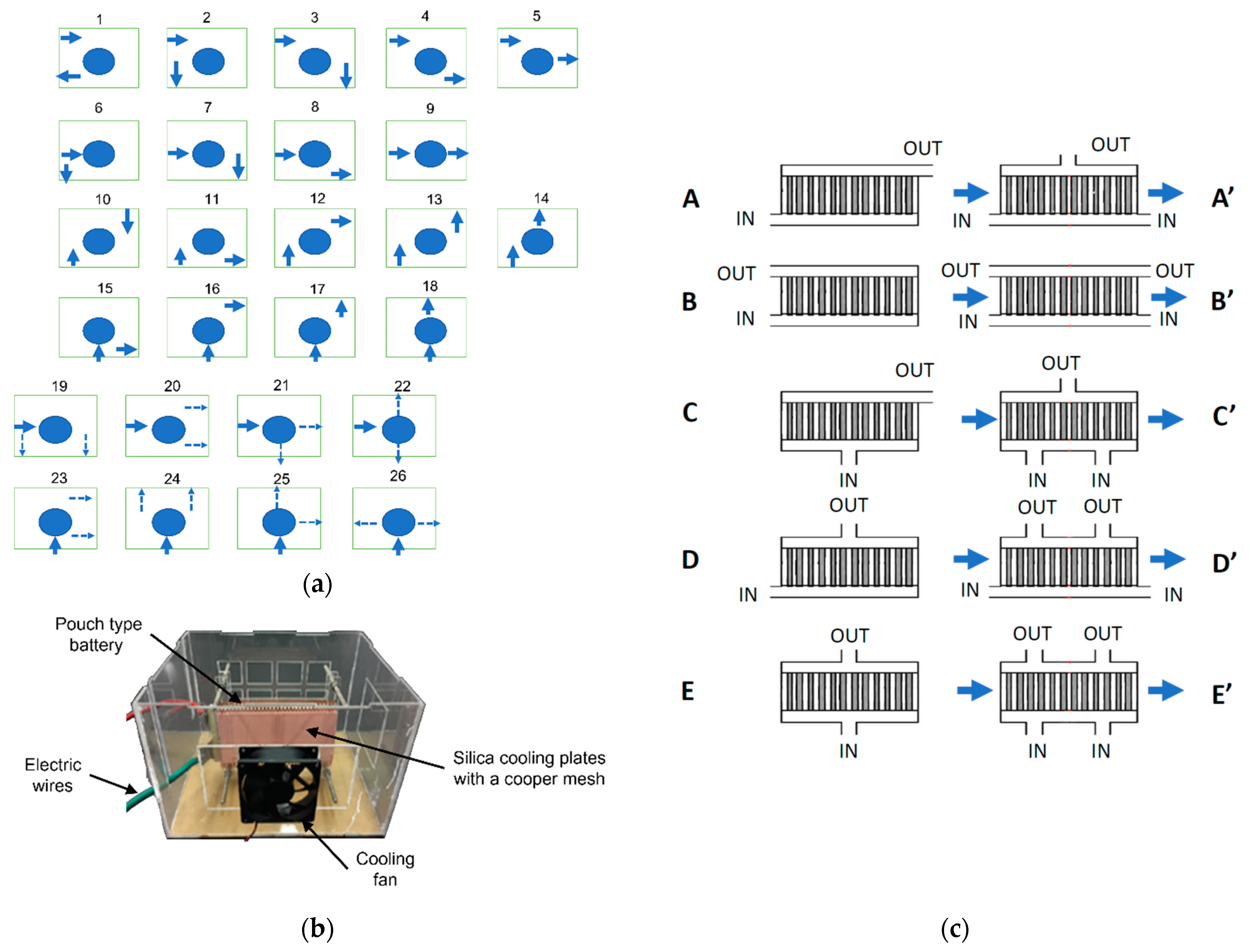
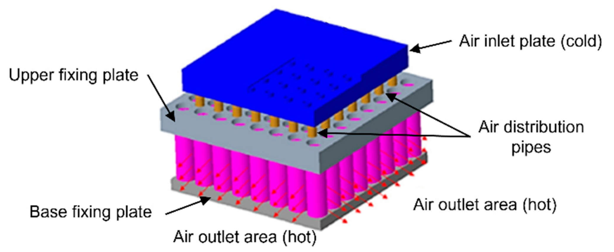
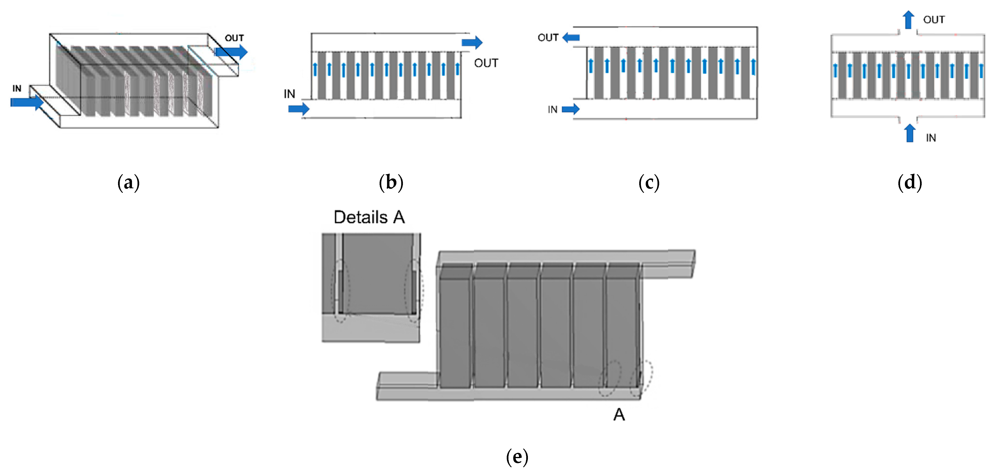
The most important characteristics of a BTMS include a small size, low weight, inexpensiveness, ease of installation, rigidity, reliability and easy maintenance [52]. The main classifications of these systems are the following: active or passive, series or parallel, cooling or heating, air or liquid or phase change material (PCM) or heat pipe (HP) or thermoelectric cooler (TEC) [28,39,53,54]. Active systems consume extra energy to power fans or pumps and are usually implemented in air and liquid cooling systems. Passive systems need specific structures on the surface of batteries to remove heat, such as PCMs or HPs. Generally, active systems have a better heat dissipation capacity, at the cost of increased complexity. PCM-based passive systems are generally used with the aim of improved temperature uniformity, while HP-based systems for their very high thermal conductivity and quick response [55].

3.1. Air-Based BTMS

The advantages of these systems are the low cost, simplicity, light extra weight [56,57], and despite their low-conductivity and low-efficiency [58], they are still studied by researchers and used in electric-driven vehicles. A first classification of air-based systems can be made considering whether it is natural or forced convection. Despite its simple structure, the natural method creates large thermal gradients in the battery pack and is highly dependent on ambient conditions [59]. Therefore, a forced-air system is necessary for most applications, despite its higher costs and additional power consumption. A second classification of air-based systems is based on the source of the air, which can be external, cabin pre-conditioned or pre-conditioned by an auxiliary heat exchanger [6].
Regardless of the battery shape, one of the main research directions is the air flow inlet and outlet scheme. Peng et al. [60] made a numerical investigation of different battery configurations, different positions of the air inlet and outlet, and the number of inlets and outlets. After demonstrating that for a battery pack of 20 cylindrical cells the best layout is a 4 × 5 scheme, the authors proposed 18 schemes regarding the inlet and outlet positioning, presented in Figure 1a. Schemes 3, 4, 12 and 13 give the lowest maximum temperature, due to the air flowing through almost all the areas inside the battery pack. An optimization study is made considering a BTMS model with multiple outlets, also shown in Figure 1a, which can slow down the battery heating process. The authors concluded that a longer fluid flow path results in a more uniform temperature distribution, both the minimum temperature and the smallest temperature gradient being obtained in scheme 24. Similar air-cooling configurations are numerically investigated by Chen et al. [61], comparing the thermal performance of asymmetrical and symmetrical parallel air-cooled BTMSs for prismatic batteries. By analyzing various inlet and outlet positions, as shown in Figure 1c, the authors found that the symmetrical systems achieve lower maximum temperature and better temperature uniformity. Various inlet positions and with different number of fans were experimentally investigated by Li et al. [62]. A novel BTMS was proposed by using silica cooling plates with a copper mesh, presented in Figure 1b. The measurements show that for a 5 C discharge rate and an inlet air velocity of 5 m/s, the 1.5 mm thick double silica cooling plate design offers the best results. The authors also found that for the analyzed pouch cells, the side cooling is more effective than the frontal one.
Akinlabi et al. [63] conducted an experimental investigation of an air cooling BTMS with symmetrical vents, at different air flow rates and C-rates. The results point towards the hypothesis that for each current rate there is an optimal air flow rate, above which extra flow will offer little improvement at the cost of increasing energy consumption. The authors suggest that in order to obtain an effective air-cooled BTMS for EVs, bidirectional flow paths are necessary. Wang et al. [64] proposed a reciprocating air flow strategy to reduce the temperature gradient on the surface of a laminated pouch battery. Using infrared images at different depth of discharge (DOD) values, the authors concluded that at the beginning of the discharge process the air flow direction should be forward (towards the terminals) and then change its direction only at a certain DOD. For a 3C discharge rate, the reciprocating process is best to start at 50% DOD. It was found that aperiodic cycles offer the optimum temperature distribution throughout a discharge process, the maximum temperature difference decreasing by 49.5% compared to a one-directional flow, respectively, by 25.5% compared to an isochronous reciprocating cycle.
For prismatic batteries, Z-type, U-type and I-type air flow configurations, shown in Figure 2a–d, are commonly investigated. Zhang et al. [65] developed a transient heat transfer mathematical model that can accurately calculate air velocities and battery temperatures for the three parallel air-flow configurations. The optimization strategy proposes the increase of width around the battery with the highest temperature and the decrease around the one with the lowest temperature, which can enhance temperature uniformity. Considering all the analyzed configurations, the U-type model with optimized channel width and divergence/convergence ducts achieves the best thermal performance and the lowest power consumption. A Z-type air-based BTMS’s improvement was proposed by Wang et al. [66] by changing the flow distribution using parallel plates, adjusting the airflow velocity in each cooling channel. An example of adding two parallel plates is presented in Figure 1e. The results show that the ideal solution from a thermal point of view is to put a plate in every cooling channel, however this has a significant negative impact on pressure loss. The acceptable solution found by the authors for the analyzed system is the use of two parallel plates.
For cylindrical batteries, investigations regarding aligned, staggered and cross configurations can be made. Fan et al. [67] performed a series of tests demonstrating that besides occupying the least amount of space from these three arrangements, the aligned configuration also offers the best temperature uniformity and cooling effectiveness, followed by the staggered and lastly the cross battery pack. Regarding the air inlet temperature, although lower values reduce the maximum temperature in the pack, it is shown that an increase from 20 °C to 30 °C at 1 C discharge rate reduces temperature non-uniformity by 12% at an inlet velocity of 0.6 m/s, and by 20% at 1 m/s, respectively. Finally, the study reveals that higher air inlet velocity values lead to an exponential increase in power consumption and a decrease of power efficiency, adding that the aligned configuration requires 23% less energy consumption than the cross pack.
Zhou et al. [56] proposed a novel cooling strategy based on air distribution pipes for cylindrical batteries and investigated its performance by numerical calculations. The structure of the proposed system is presented in Figure 3. Air enters the pipes from the inlet and then is distributed in-between the batteries. The authors observed that orifices with a 1 mm diameter allow maintaining the maximum temperature below the upper limit, at 38.05 °C. An increase to a diameter of 2 mm further reduced the maximum temperature to 32.55 °C, but also resulted in an increase of temperature gradient inside the analyzed module. Moreover, increasing the rows of orifice also has a positive impact on the thermal performance. The authors also studied the effects of inlet pressure and discharge rate on the heat transfer capacity of the system, highlighting the importance of correlation between inlet pressure, discharge rate and cooling effect.

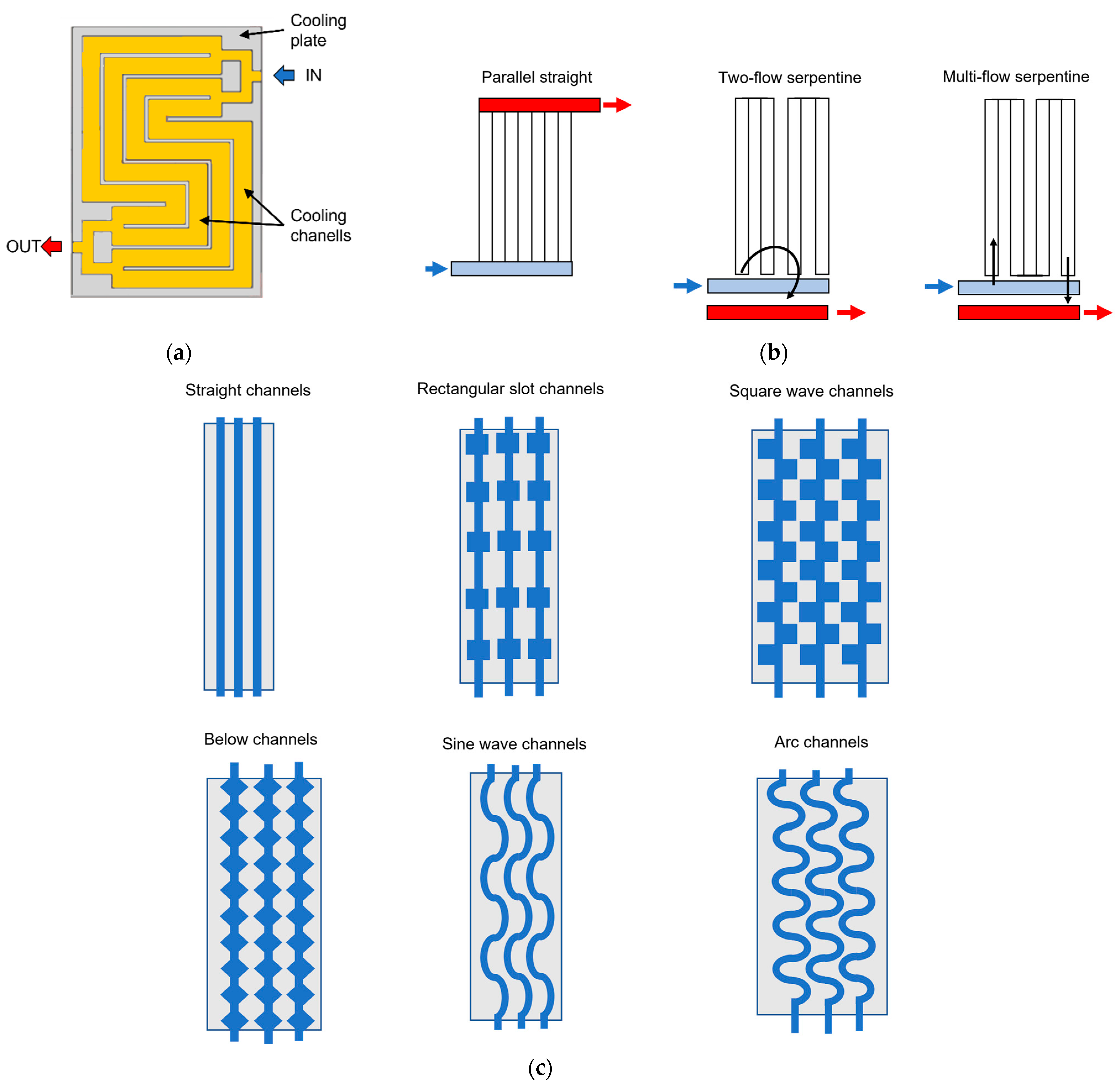
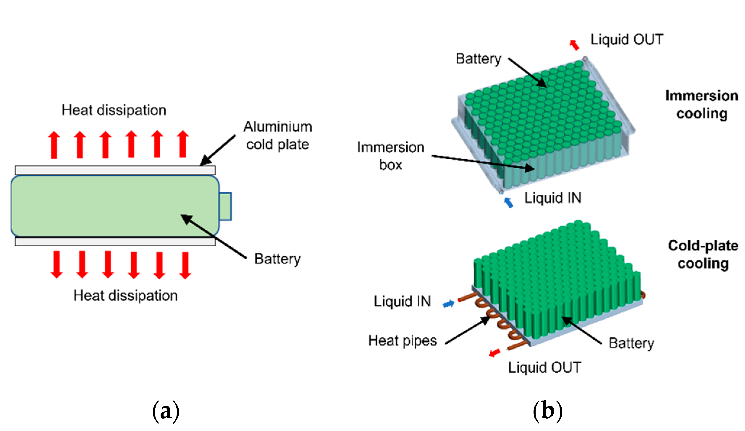
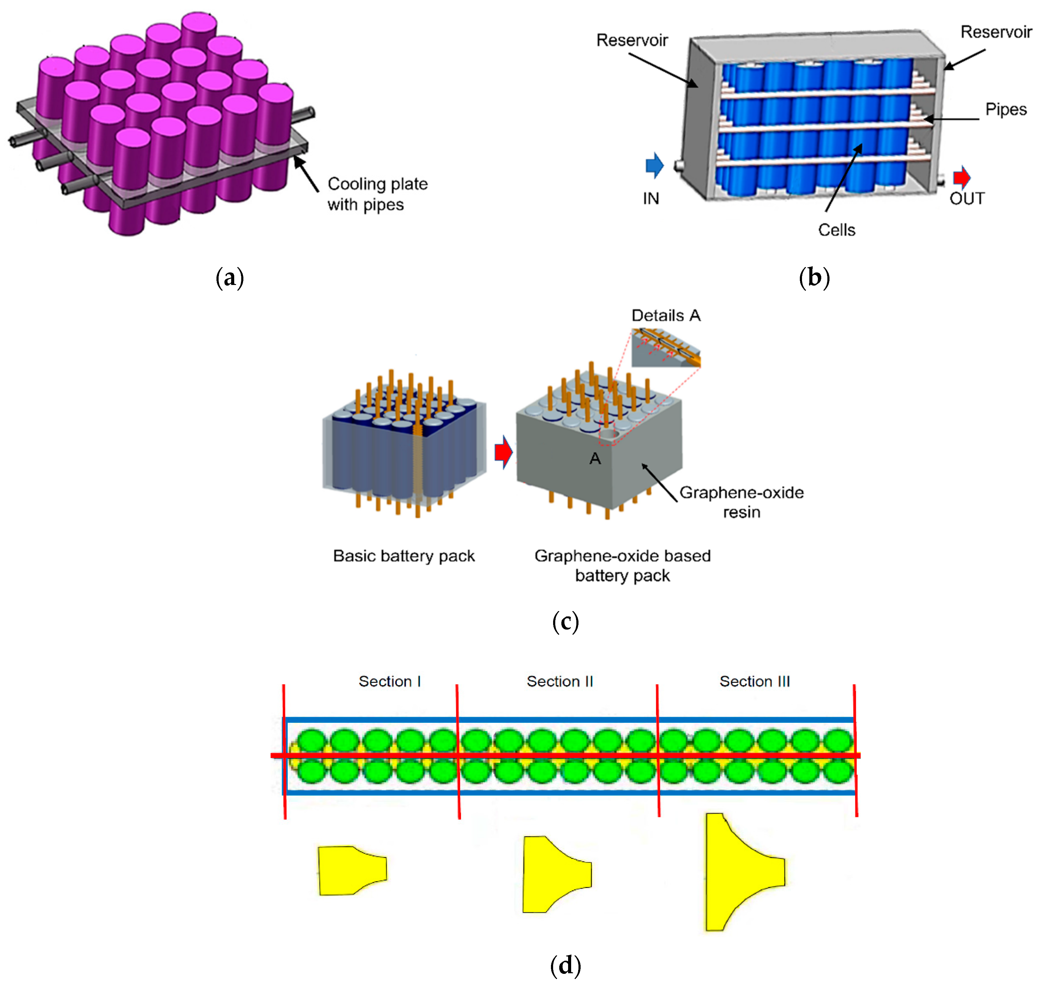
3.2. Liquid-Based BTMS
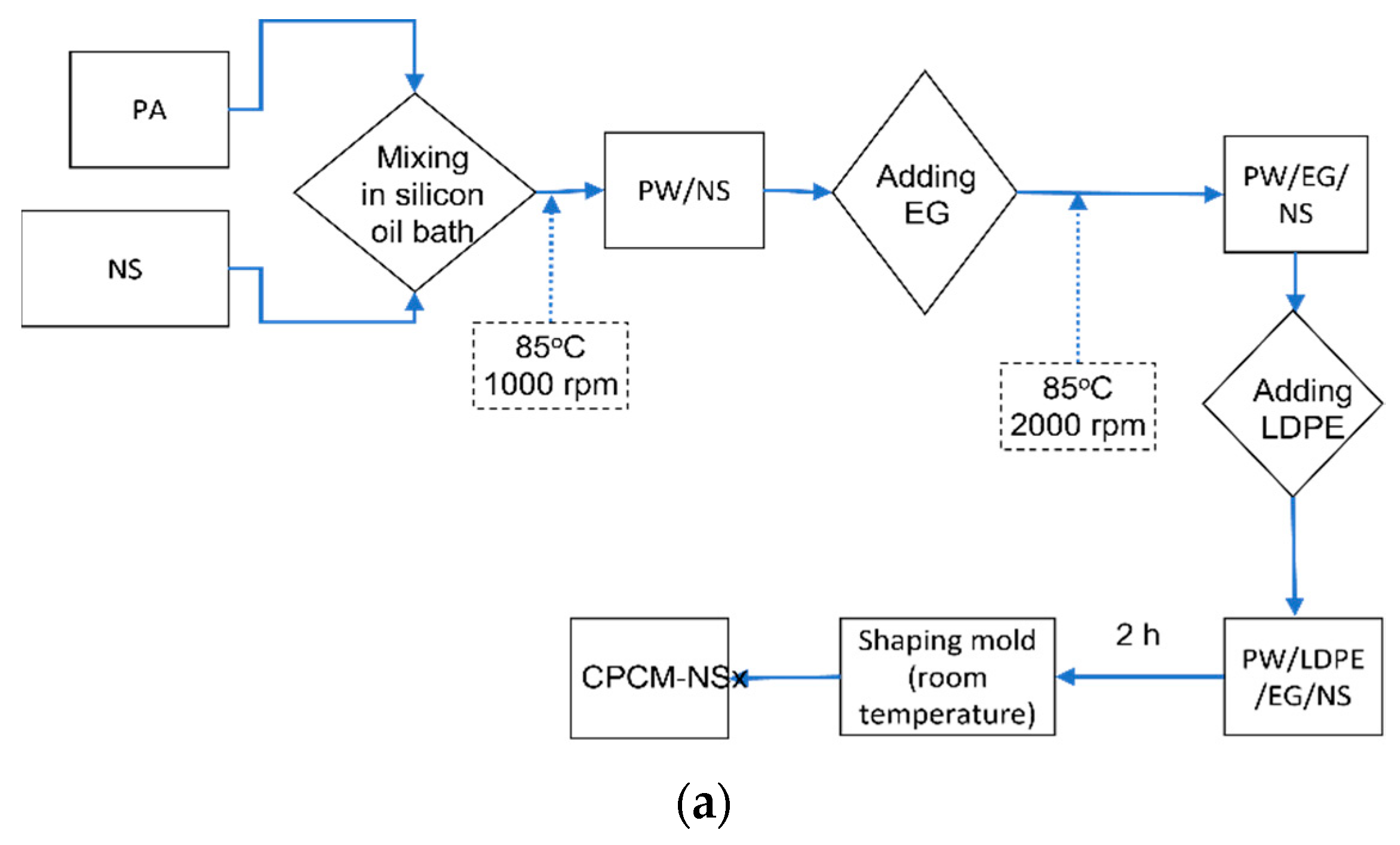
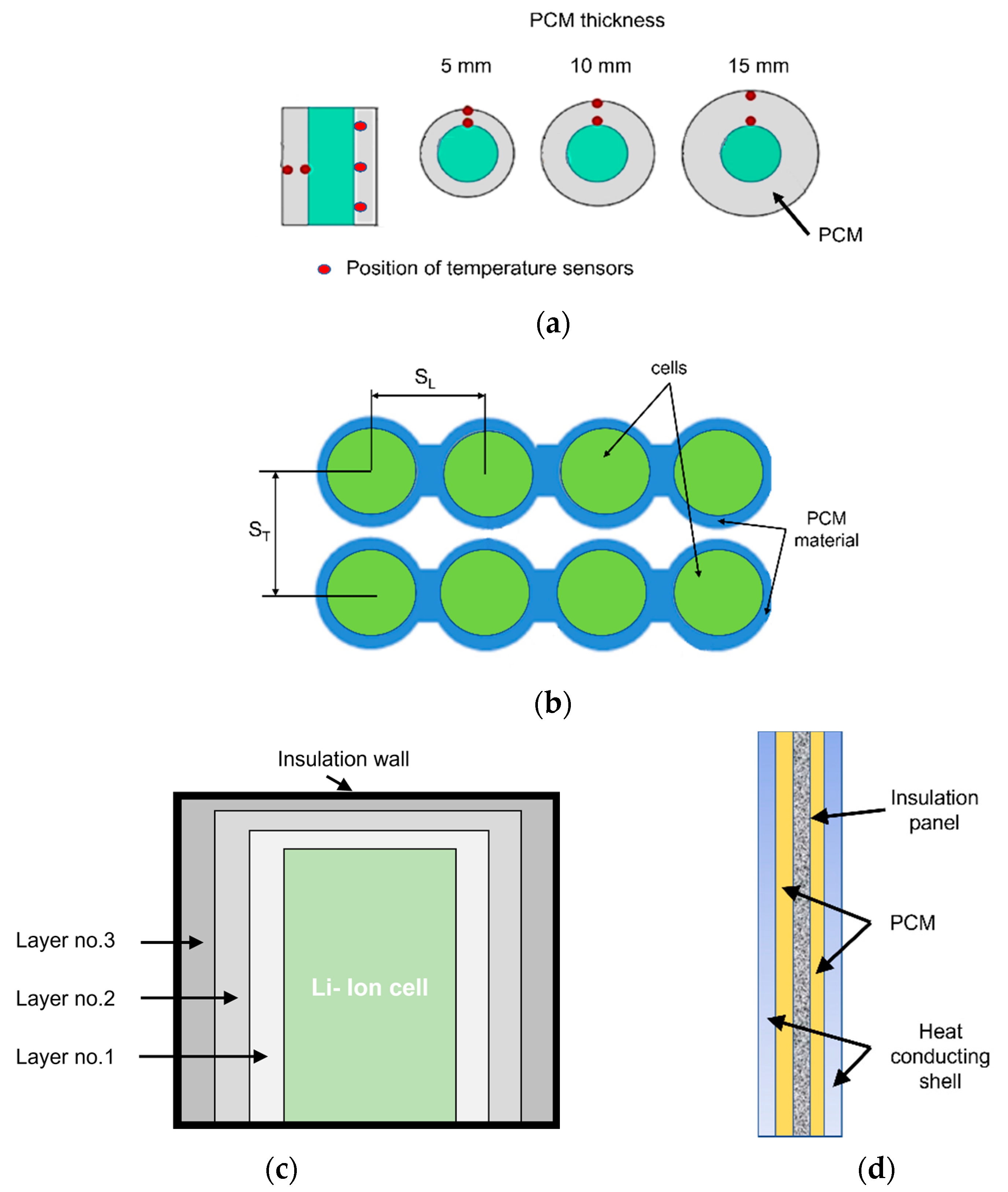
Liquid-cooled systems are the most used in practical applications [39], due to their high efficiency and compactness. Liquid possesses good heat capacity and heat transfer coefficient, representing a suitable solution for the BTM of EVs [68]. Compared to an air-cooling system, 2–3 times less energy is needed to maintain the same average temperature of the batteries [69]. The disadvantages are the increased complexity, added weight, extra costs, rigidity of the structure [55,70]. Moreover, a significant additional power is required to circulate the fluid at the desired flow rate, increasing the overall energy consumption of the vehicle [71].
Liquid-cooling is easily applicable for prismatic batteries due their regular shape, allowing a compact arrangement of the BTMS, while cylindrical batteries require special structures to integrate the cooling channels, increasing the system’s complexity and mass. The most common solution for prismatic and pouch batteries is the implementation of cooling plates. General investigations analyze the temperature and velocity distribution inside the cooling plates [72], and several studies [73,74,75] investigate by means of orthogonal test the influence of different parameters, such as liquid inlet temperature, cooling plate width, mass flow rate or number of channels. Shang et al. [73] obtained an improvement of 12.61% compared to the maximum temperature without the orthogonal optimization. Ye et al. [74] achieved a lowering of maximum temperature by 5.24% and of the pressure drop by 16.88%. The sensitivity analysis of the orthogonal test also showed that the greatest influence on the pressure loss is caused by the center channel distance and the size of the inlet plenum. The numerical calculations conducted by Monika et al. [75] showed that for cold plates placed between the batteries, a parallel flow arrangement with the inlet placed near the tab region represents the best solution. The authors found that a 5-channeled cold plate of 4 mm width represents the best trade-off between heat transfer and pressure drop. Patil et al. [76] conducted a parametric study to evaluate the thermal performance of different U-turn type microchannel cold plates. The results suggest that a surface area coverage ratio of 0.75 and a hydraulic diameter of the channels of 1.54 mm offer the best cooling capacity. The numerical simulations also show that alternating single inlet and outlet channels decrease the maximum temperature and improve temperature uniformity.
Cai et al. [29] investigated the effect of mass maldistribution on the temperature uniformity of cooling plates, especially from the point of view of channel configuration. The authors concluded that serpentine flow channels offer a better mass distribution than the cavity or parallel configurations. Splitter blades as shown in Figure 4a are used to reduce pressure drop and the results show that narrow channels and longer distances of h2 offer the better thermal performance for cooling plates. A double-layered cooling channel is proposed by Deng et al. [77], where the coolant enters the cold plate and converges to the center, and then through a vertical connection flows along four diagonal straights channels towards the outlets. The conducted multi-objective optimization shows that the proposed design has better performances than the conventional serpentine and parallel straight channels. Amalesh et al. [78] investigated new mini-channel cold plate designs for the lateral cooling of prismatic batteries, operating at a discharge rate of 3 C. The new proposed designs are represented in Figure 4c. Although all seven designs present better cooling capacity than the conventional design and offer an improved temperature uniformity, the circular slot channel and the zig-zag channel design seem to be the most suitable from a thermal point of view. However, a more detailed study also shows that for almost the same cooling performances, the zig-zag profile causes about 3 times larger pressure drops, proving it not to be the ideal solution to be implemented in the analyzed BTMS. Shen et al. [79] propose a conventional cold plate structure beneath the prismatic batteries, but using refrigerant as coolant medium, and investigated the effects of different flow structures of the cold plate, presented in Figure 4b. The numerical calculations show that although the longer flow paths have a better cooling effect, the increase of the refrigerant’s pressure drop is far more significant. Regarding the cross-section of the channels, the decrease of channel thickness causes an increase in collision and friction during the movement of bubbles, which enhances the heat transfer capability of the refrigerant. Moreover, transient simulations show that due to the transition phase of the refrigerant at nearly constant temperature, temperature differences between batteries can be greatly reduced by such a cooling strategy.
Zhang et al. [80] investigated the effect of adding a thermally conductive interface between the batteries and the cold plate, as shown in Figure 5a. The authors prepared a hexagonal boron nitride and silicone rubber (h-BN-SR) composite which presents better mechanical properties and thermal conductivity than pure silicone rubber. At a constant discharge rate of 4 C, the use of the prepared interface decreased the maximum battery temperature by 2.9 °C compared to a 50 µm interface gap. Other studies [81,82] performed comparative analyses between cold plate and other type BTMSs. Dubey et al. [81] compare the performance of immersion cooling and cold plate cooling for cylindrical batteries, the two systems being presented in Figure 5b. The numerical simulations show that at high C-rates the immersion cooling leads to significantly lower battery temperatures. Simultaneously, temperature uniformity across the module is better using a cold plate, because of the higher heat transfer rate and lower thermal characteristics of the dielectric fluid. It was observed that for the same liquid flow rates, immersion-based cooling results in 2.5–3 times better thermal conductance and 15–25 times lower pressure drop compared to the cold plate. Bhattacharjee et al. [82] performed a comparative study between an air-cooled, liquid-cooled with cold plate and immersion-based BTMS. Proving that liquid-cooling is more effective than air-cooling, the authors propose a cooling system where the pouch batteries are covered by a nonmetallic sheet and immersed in a dielectric fluid. Such a cooling strategy allows the dissipation of heat in a shorter period, therefore improving the thermal performance of liquid based BTMS.
Wang et al. [83] investigated a liquid-based cooling system using another coolant medium than the commonly used water, water/glycol mixture or mineral oil. Indicating the low energy storage density of these coolants, the authors suggest the use of novel coolants made of phase change material (PCM) emulsions, which flow inside 4 mm diameter tubes contained in a heat sink around the cylindrical batteries, as presented in Figure 6a. In the study, two phase change material nano-emulsions containing 10 wt% and 20 wt% OP28E were prepared and investigated from the point of view of their dispersion stability, thermophysical properties or thermal reliability. The studied emulsions showed 1.32 times and 3.65 times improved energy storage capacity compared to water. A different coolant medium is proposed also by Liu et al. [84], who present a BTMS based on liquid metal, which can endure extreme conditions with high ambient temperatures or high discharge rates better than water. Given the shape of the analyzed cylindrical cells, a thermal conductive structure is used with copper pipes as a heat transfer channel, as shown in Figure 6b. An important part of such a study is the power consumption analysis, and the authors found that a variable velocity strategy instead of a traditional constant velocity one can significantly improve the energy efficiency of the BTMS.
A thermally conductive structure around cylindrical batteries combined copper pipes is developed also by Lv et al. [70] and illustrated in Figure 6c. The graphene oxide-modified silica gel has an improved thermal conductivity and transfers the heat efficiently to the fins-enhanced cooper cooling tubes. The analyzed water-cooled battery module presents better cooling capabilities than an air-cooled or a liquid-cooled module without the silica gel. During fast-charging operations with 2 C and 3 C rates, the maximum temperature of the module is at 37.7 °C and 42.0 °C, respectively, while the maximum thermal gradient is kept below 4 °C and 5 °C. Tang et al. [85] proposed a novel liquid-cooling BTMS using microchannel in a heat conducting block with variable contact surface around the cylindrical batteries for a better temperature uniformity, as illustrated in Figure 6d. The authors demonstrated that the bigger the angle difference between contact surfaces, the lower the temperature gradient in the module, while the maximum temperature is also reduced. From a temperature difference of 3.95 °C at an angle difference of 2.5°, the system descended to 2.58 °C at 15°. Moreover, the authors demonstrated that the concept with variable contact surface is benefic for temperature uniformity both for cooling and preheating performance.
Wavy channels with liquid flow are another solution for cylindrical batteries and are also adopted by automotive companies like Tesla [6]. The mathematical model developed by Zhao et al. [86] for simulating the thermal behavior of cylindrical batteries cooled by wavy channels with liquid flow show that at the correct fluid inlet conditions (0.5 m/s inlet velocity and 25 °C), the channeled liquid cooling system has the capacity to maintain maximum temperature below 35 °C and maximum temperature difference below 1 °C. Given the risk of increased temperature non-uniformities, especially for the batteries that are close to the outlet of channeled liquid cooling systems, the authors propose heat transfer enhancement methods for the downstream batteries or multi-passage short channels to replace the long wavy single channel. Zhou et al. [87] highlighted the possibility to use half-helical duct structures as a heat exchanger around cylindrical batteries, as shown in Figure 7. Some advantages of such a system are its compact structure, the improvement of heat transfer due to the mixing of fluid particles and the large number of possibilities regarding the number and location of inlet and outlet connections. The pitch and number of helical ducts did not show any significant differences in the cooling performance, however the concept of alteration of flow direction reduced the maximum temperatures to 30.5 °C and 4.6 °C, respectively, while a larger diameter of the helical ducts also proved to be beneficial.
Cao et al. [88] addressed the problem of numerically investigating a full-size battery pack. It is highlighted that in such an analysis the attention is directed towards the power consumption of the entire system, the coolant flow distribution between different modules and even the electrical circuit networking connection. The study proposes a new design for T-junctions, aiming the reduction of temperature non-uniformity between the modules and enhance flow distribution, with regard to the Reynolds number and pump power requirements.

3.3. PCM-Based BTMS

Phase change materials represent an interesting alternative to the conventional forced-air and liquid cooling systems, because it could allow the implementation of a passive BTMS. It is applied especially for cylindrical batteries, because it allows the filling of the unused spaces between the batteries. PCMs have high latent heat capacity and are able to maintain the temperature of the batteries in a small range, close to the melting temperature of the PCM [89]. The melting point is in the 5.5–76 °C temperature range and the phase change process is usually not isotherm [9]. In case of continuous charge and discharge cycles at high rates, there is the risk of the PCM melting completely, leading to thermal instability and leakage of the PCM. Moreover, the melting of the PCM automatically increases its volume, which must be considered when designing a PCM-based BTMS. Another disadvantage of PCMs is their low thermal conductivity, resulting in a difficult heat dissipation.
Numerous studies addressed the problem of low thermal conductivity. Azizi et al. [90] constructed a BTMS made of PCM and aluminum wire mesh plates as a thermal conductivity enhancer. The wire mesh plates with high voidage values are preferred over the aluminum foams for a better filling of the pores during the phase change of the PCM. Zhang et al. [91] study the influence of different concentrations of aluminum nitrite (AlN)-based CPCMs. The measurements showed that increasing the AlN mass fraction improved thermal conductivity from 1.48 W/mK to 4.331 W/mK at 50 °C, as well as the tensile strength, bending strength and impact strength. Zhang et al. [92] designed and experimentally investigated a BTMS using copper metal foam saturated PCM. For a 5 C discharge rate the maximum temperature was lowered to 47.86 °C compared to 54.115 °C in the case of pure PCM. The temperature non-uniformity increasing rate also showed smaller values. Jiang et al. [93] addressed the problem of low thermal conductivity of paraffin by absorbing it into expanded graphite (EG) with various mass fractions and then by compressing the resulted powder into cylinder-shaped samples. The authors found that an increased EG mass fraction results in an improved thermal conductivity of 13.85 W/mK, and in a decreased PCM leakage, being at 0.38 wt% loss after 10 phase change cycles, without impacting significantly the phase change temperature of the pure PCM. Wu et al. [94] suggest that an EG mass fraction of 15%–20% is recommended in order to increase thermal conductivity. An enhanced CPCM is proposed, made of pyrolytic graphite sheets (PGS), which presents better heat dissipation and temperature uniformity compared to PCM. The propagation of thermal runaway is also analyzed, the PCM/PGS module needing a smaller spacing between batteries to prevent propagation, leading to a reduction of 71.4% in volume compared to the PCM module. Talluri et al. [95] concluded that expanded graphite PCM is the best solution for PCM-based BTMS, enhancing heat transfer rate by 16.4%, and observed no leakage using this solution. During high discharge rates of 25 min, the maximum temperature with PCM increased to 28 °C compared to 35.9 °C without PCM.
Besides low thermal conductivity, the problem of PCM leaking has also been intensely investigated. In liquid phase the homogeneity of the PCM module decreases, and even worse, safety risks rise because of the build-up of leaked, combustible PCM. A solution could be microencapsulation, but high costs [96], the required laborious procedures [97] and the change in volume during temperature variations [98] reduce its applicability. Chen et al. [99] proposed a PCM with high thermal conductivity and a solid-solid phase change, enhanced with fins to further increase thermal performance. Lv et al. [100] developed a paraffin-based CPCM with improved anti-leakage and anti-volume-change properties, obtained by adding nanosilica into the CPCM, conform the schematics from Figure 8a. The nanosilica dispersed in the expanded graphite pores adsorb liquid phase paraffin and restrain the expansion of graphite. This prevents leakage and reduces greatly the volume change of the system. The results show that after 20 h at 55 °C the loss of mass of the prepared samples is 1.15% for CPCM-NS0, 0.54% for the CPCM-NS7 and the lowest 0.39% for the CPCM-NS5. When increasing the temperature to 60 °C, these losses become 4.08%, 1.25% and 0.53%, respectively, showing that a too high participation of nanosilica can lead to an increase of leakage, because of the aggregation of nanosilica resulting in a non-homogenous distribution of the CPCM’s components. The volume change experiments show that the volumetric thermal expansion increment in CPCM-NS0 is 4 times higher than that of the CPCM-NS5.5, which also means a better cooling performance of the proposed CPCM due to the reduced gap between the batteries and the CPCM module. Liu et al. [101] also focused on preparing a low leakage CPCM with high thermal conductivity and high latent heat. The proposed paraffin/expanded graphite/high-density polyethylene/nano-silver CPCM is presented in Figure 8b. Huang et al. [102] developed a flexible form-stable CPCM in order to overcome both the issues of paraffin leakage after melting and of high thermal contact resistance of rigid CPCMs. Flexible polymer is used as a supporting material and expanded graphite is added to enhance thermal conductivity. The proposed solution reduces thermal contact resistance to 461 mm2 K/W compared to 1818 mm2 K/W for a conventional CPCM, which means a reduction of temperature by 6.5 °C.
Huang et al. [103] also highlight the need of increasing thermal conductivity of pure PCM, but simultaneously express the necessity of finding a balance between latent heat and thermal conductivity. The authors declare that above 5 W/mK the decrease of maximum temperature becomes less significant and suggest an optimal latent heat of 225 J/g and an optimal porosity of 94% for the best thermal management performance.
Yan et al. [104] conducted an experimental study to determine the optimal phase change temperature of a PCM used in BTMS, highlighting the need to test these systems in dynamic cycling, which is closer to real-life conditions. The authors compared three PCMs with phase change temperatures of 36, 45 and 58 °C. The experiments prove that in dynamic cycling conditions, the laying-aside time between steps is of great importance. The authors recommend the use of the PCM with a phase change temperature of 45 °C. Gscwander et al. [105] analyzed the storage capacity of different PCM emulsions in function of their phase transition behavior and supercooling effect. The melting temperature of the different PCMs was between 16 and 40 °C and a 35 wt% formulation was prepared for the emulsions. Compared to water in the same temperature range, storage capacities increased 2–2.7 times.
Weng et al. [106] investigated a single cylindrical battery surrounded by a PCM layer, analyzing the effect of three layer thicknesses, illustrated in Figure 9a. Given that a too thin PCM layer cannot store enough thermal energy, while a too large one decreases the energy density of a battery pack, the authors found that the optimal cooling performance is offered by the 10 mm thick PCM layer. Jilte et al. [107] highlighted the disadvantages of the conventional PCM-based BTMS, consisting of a rectangular PCM-filled battery pack, namely the difference of heat rejection rate between the batteries in the middle and the corner of the pack. A different cooling system is proposed, consisting of embedded PCM flow passages, presented in Figure 9b. The numerical simulations show that a 4 mm thick PCM is sufficient for heat dissipation, the maximum cell temperature rise being below 5 °C under 40 °C ambient air temperature supply. Additionally, the temperature uniformity is kept within 0.05 °C at 2 C rate and below 0.12 °C at 4 C discharge rate. Nasehi et al. [108] investigated the use of three PCM layers around a prismatic battery, as shown in Figure 9c, each PCM having different properties, but concluded that the best performances are attained when using a single PCM. Another concept presented by Zhao et al. [109] focuses also on the capacity of preventing thermal runaway propagation in a battery module, by means of a PCM composite board illustrated in Figure 9d. In order to balance heat transfer and thermal isolation capacity simultaneously, the authors propose a structure composed of a thermally conductive shell, PCM to absorb the generated heat and an insulation panel in the middle of the structure, to slow down heat transfer between batteries and improve safety.
Ling et al. [110] analyzed the thermal performance of PCMs with different thermal conductivities at low-temperature operation. Two composites are prepared, a 60 wt% RT44HC/expanded graphite with high thermal conductivity, and a 60 wt% RT44HC/fumed silica with low thermal conductivity, and tested in a BTMS at −10 °C and 5 °C. Although the warm battery does not cool down as fast, PCMs with low thermal conductivity are not suited for BTMSs, causing significant temperature differences in the pack (>12 °C). The composite with expanded graphite prevented the overheating of the battery and improved temperature uniformity. Zhong et al. [22] proposed a BTMS able to cool but also preheat the battery pack for insuring normal operating temperatures also in cold climates. The study presents CPCM cooling with an additional resistance wire preheating function, as shown in Figure 10. The preheating system can increase battery temperature to 40 °C in 300 s, using slightly more energy than a pure resistance wire system.

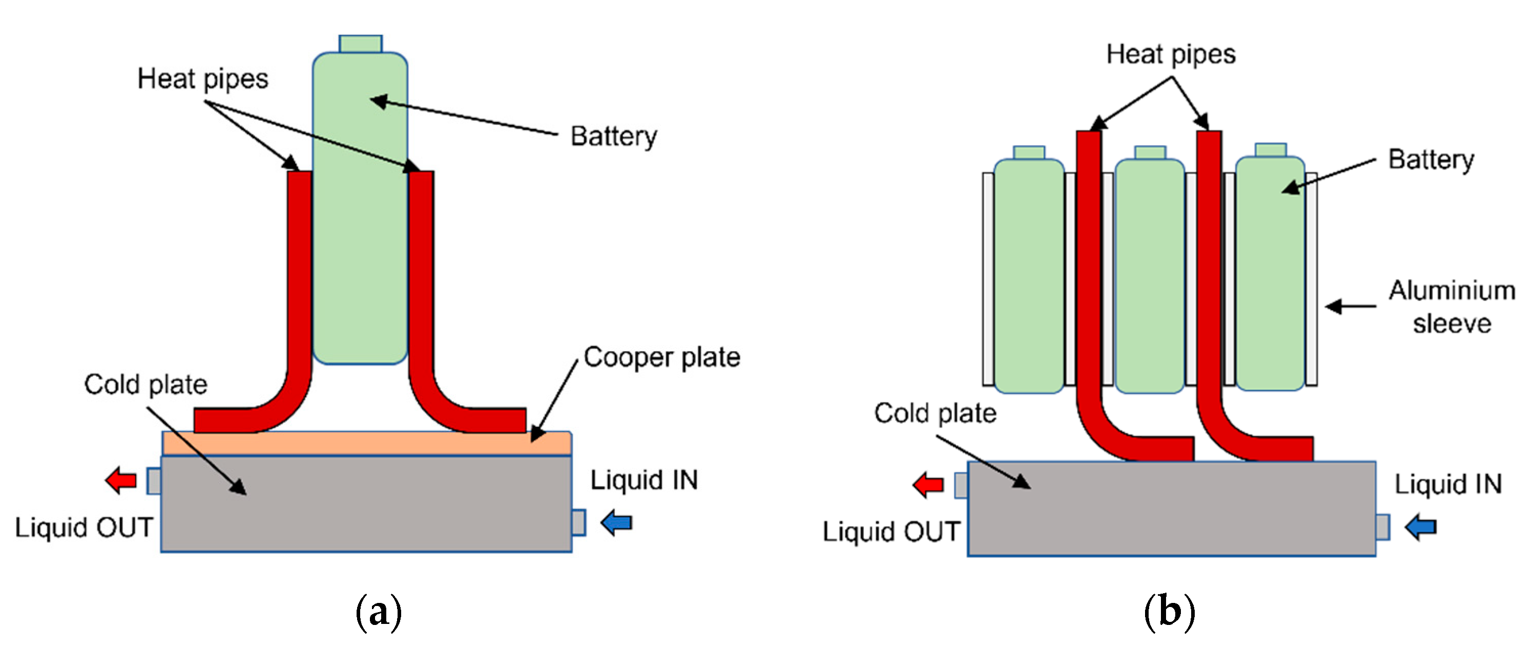
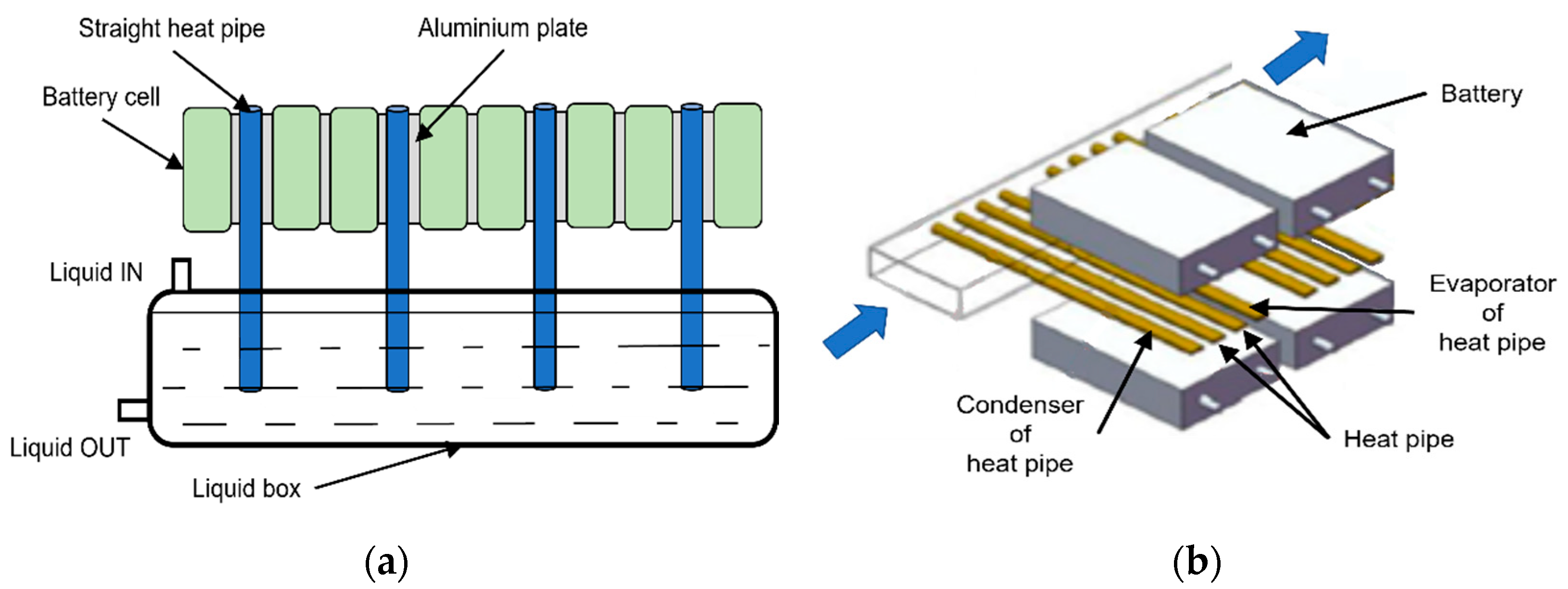
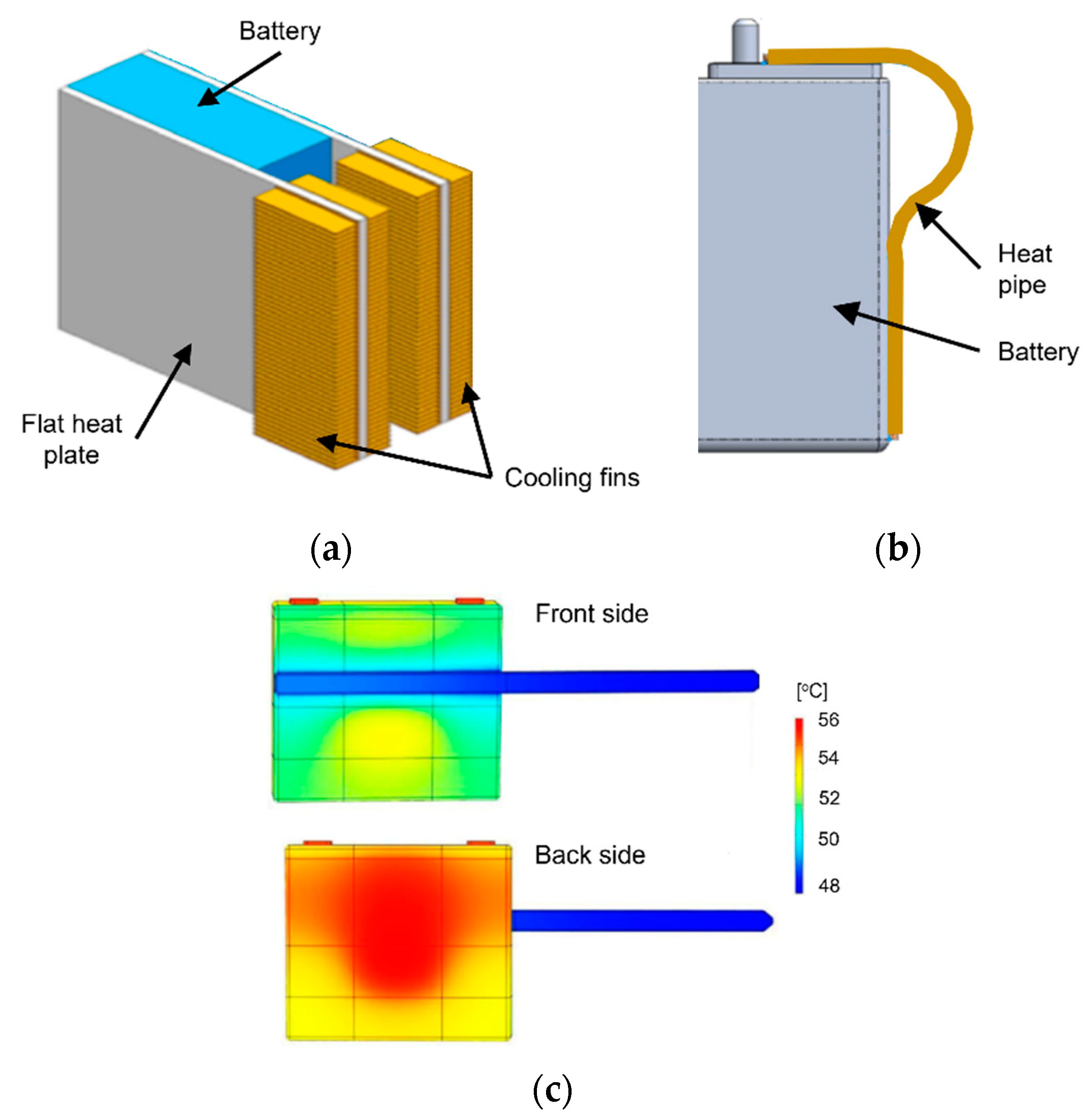
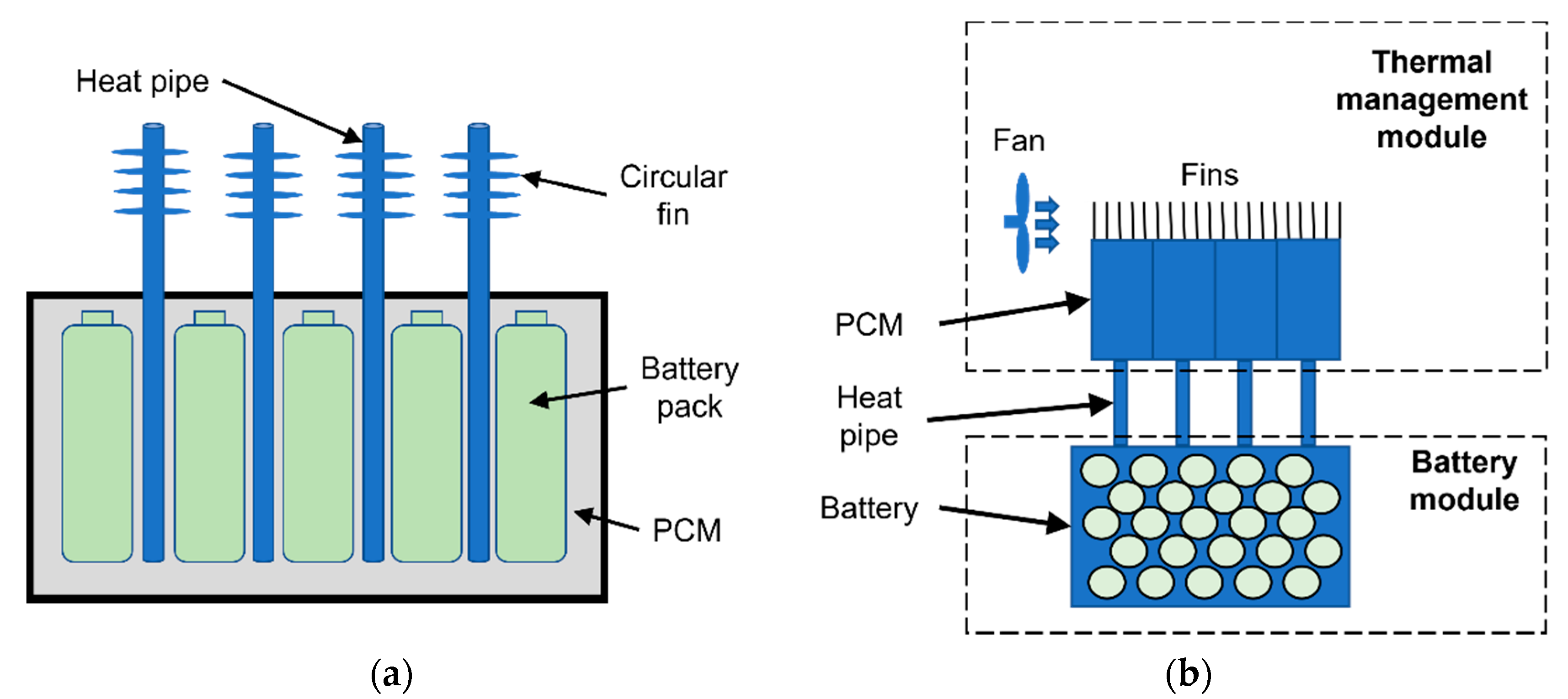
3.4. Heat Pipe-Based BTMS
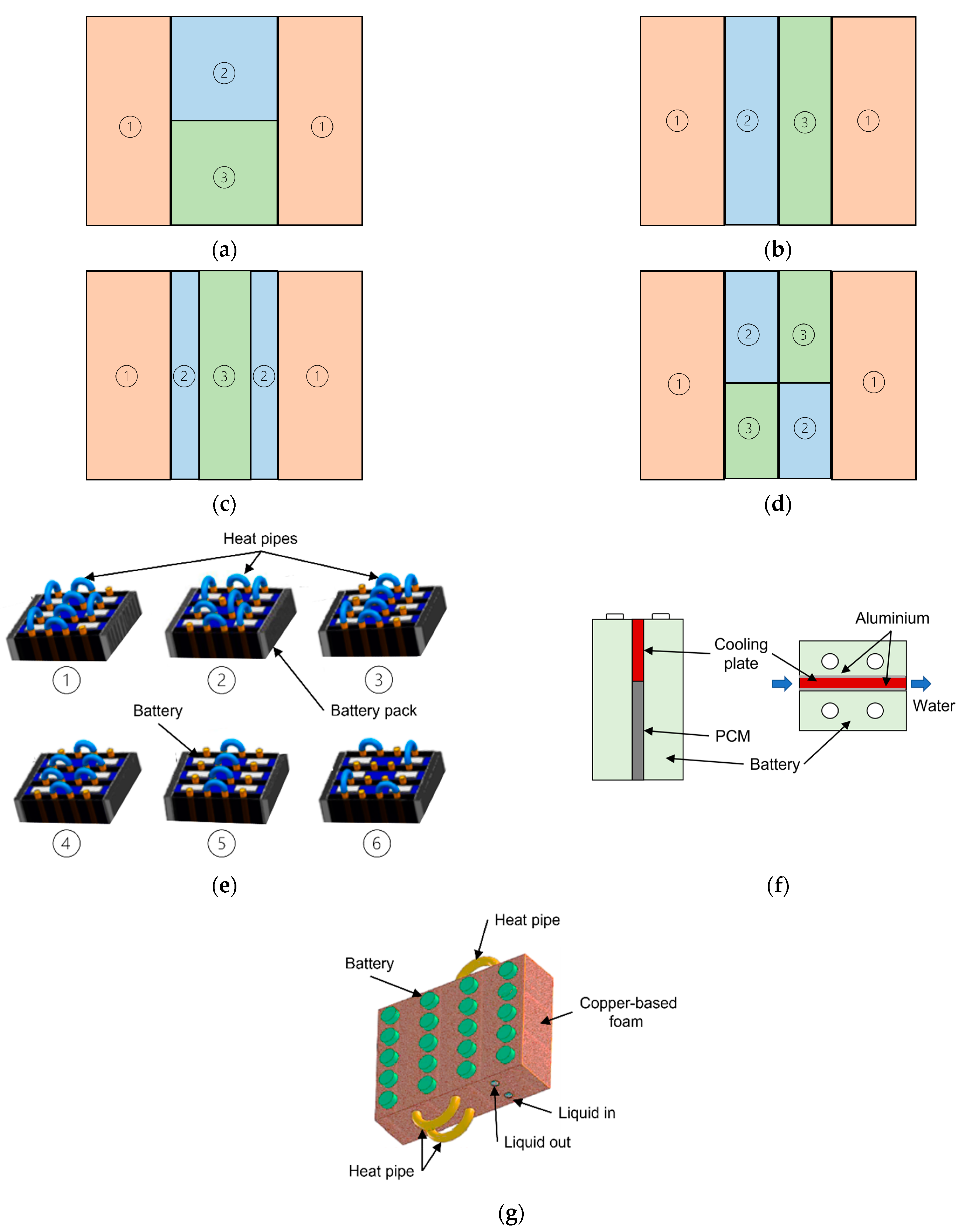
Heat pipes are heat transfer devices with extremely high thermal conductivity, 90 times higher than copper [111], ensuring better heat dissipation and temperature uniformity. They represent a passive, compact, lightweight BTMS, with no need of maintenance and long life cycle [112]. The working principle consists in the phase change of the internal working fluid, which absorbs heat at the evaporation section and releases it at the condensation section. As long as there is a temperature gradient between the two sections, the transfer of heat goes on, without any power consumption. Despite its very high thermal conductivity however, in most applications heat pipe is coupled with forced air or liquid cooling for a more effective heat dissipation at the condensation section.
Heat pipe-based BTMSs are studied mostly for prismatic and pouch batteries due to the adaptability of the shapes and the large available contact areas, while in case of cylindrical batteries special attention needs to addressed to the contact surface between heat pipe and batteries.
Zhang et al. [113] proposed a passive heat pipe-based BTMS for prismatic batteries, using flat heat pipes with fins, as presented in Figure 11a. Compared to natural convection and aluminum plates, the maximum temperature was 73.7% lower and the maximum temperature difference 50.1% lower. Behi et al. [112] designed a smart heat pipe-based BTMS, using the least number of heat pipes based on the multizone analysis of temperature distribution determined by thermal imaging. The high discharge investigation revealed that the most critical zone of a prismatic LTO cell is the center top region. The thermal analysis, illustrated in Figure 11c, showed that a single heat pipe with an optimal placement is sufficient. Kleiner et al. [114] introduced a concept where heat pipes are attached to the terminals of prismatic batteries, as presented in Figure 11b. This reduces the heat flow path and thermal resistance from the heat generation sources, located in the busbar and inside the battery, to the cooling system at the bottom of prismatic batteries. The results show that without any increase in charging time, temperature at the terminals and in the jelly roll are 19 °C, respectively 2 °C lower. Temperature distribution is also improved, due to conduction of 27% of the generated heat.
Liu et al. [115] highlighted the necessity of developing more accurate mathematical models that describe the heat transfer characteristics of heat pipes. The authors propose a segmented thermal model in which the evaporator and condenser region have their own individual equivalent conductivity and thermal parameters, which proves to be more accurate than the traditional non-segmented model. Additionally, the results show that for an effective heat pipe based BTMS it is recommended to have assistance by forced convection.
Pulsating or oscillating heat pipes (PHP or OHP) have a simple structure to work during a two-phase flow regime, due to the thermally driven back-and-forth oscillation of bubbles and liquid plugs within its serpentine tubes. Moreover, conventional working fluids can be replaced with other mediums that improve heat transfer performance. Chen et al. [116] proposed an improved pulsating heat pipes using water-based TiO2 nanofluid as working medium. An increase in battery heat generation leads to an increase in the temperature gradient between the condensation and evaporation section of the hat pipe, leading to an accelerated start of the PHP. Simultaneously, an ambient temperature increase to 35 °C is overcame by the proposed system, resulting in a maximum temperature of 42.22 °C on the battery surface and a maximum temperature difference below 2 °C. Wei et al. [117] proposed a plug-in oscillating heat pipe consisting of a flat-plate evaporator and a tube condenser, using as working fluid binary-fluid mixtures of ethanol aqueous solution. The measurements show that the volumetric filling ration and water–ethanol mixing ratio have a significant influence on the thermal performance of oscillating heat pipes, affecting startup evaporator temperature, thermal resistance or air-to-boil temperature. The best heat transfer characteristics were found to be for a 1:1 water–ethanol mixing ratio and a volumetric filling ratio of 30%.

3.5. Hybrid BTMS

Hybrid BTMSs usually combine active and passive methods, with the aim of enhancing the heat transfer process of passive systems and offering the possibility to actively control their working process. In general, PCMs are used for a better temperature uniformity and the active system reduces the risk of heat saturation, while HPs are used for their high thermal conductivity which significantly improves local heat transfer and the active system enhances the heat release at the condensation section [55]. Although forced air can be successfully implemented as the active system for lower thermal load systems, liquid cooling offers higher efficiency. Another classification criterion is the combination method, which can be parallel, series or both. The main disadvantages of hybrid BTMSs regularly are their weight, volume, complexity and energy consumption.
Ling et al. [118] showed that using pure PCM as a passive system, at discharge rates of 1.5–2 C the battery temperature of 60 °C was reached at the third cycle, while using a hybrid system coupled with forced air cooling the maximum temperature was maintained under 46 °C. Another study, performed by Zhao et al. [16] compared various concepts of heat pipe-based BTMSs: natural convection, fan cooling in horizontal and vertical position, and wet cooling by immersion and by using water sprays, respectively. The study does not recommend the cooling of the condenser section in a bath, because of the formation of bubbles that drastically thermal conductivity. The results also show that the inclination angle of ultra-thin heat pipes has no effect on their performances. The water spray strategy proved to be the most efficient, keeping the maximum temperature under 30 °C with only four sprays for 3000 s.
A hybrid BTMS combining PCM and water-cooling is proposed by Molaeimanesh et al. [119], for prismatic cells in different configurations, presented in Figure 12a–d. The numerical simulations show that the PCM stay in solid phase for a longer period and that the surface temperature of the battery is better controlled with the parallel/series configuration. However, this solution offers poor thermal uniformity since both the PCM and the cooling water are in direct contact with the battery. The most reduced temperature differences are recorded for the series configuration. Another hybrid BTMS for prismatic batteries, including a high thermal conductivity and low leakage CPCM and water-cooling is presented by Liu et al. [101]. By coupling the CPCM with a single water channel during a 3 C discharge –1 C charge test, the maximum temperature was reduced from 92 to 59.5 °C and the maximum temperature difference from 16.95 to 6.1 °C, demonstrating a better cooling effect than the CPCM-only system. Further, the authors proposed several configurations by changing the hose connections, presented in Figure 12e. The lowest temperature and temperature difference are obtained using the scheme 6, with four cold-water inlets, which also means a more reduced pressure loss. The results show that in case discharge-charge cycles it is more effective the change the water inlet temperature than the flow rate. From an energy consumption point of view, when the battery pack is moderately heated, varying only the pump power for regulating the flow rate is sufficient, while during severe heat generation, both the pump and the compressor should be adjusted simultaneously. Bai et al. [120] proposed the use of a water-cooling plate placed near the electrodes of pouch batteries, where most of the heat is generated, while the PCM is used to dissipate the generated heat of other parts of the battery and ensure temperature uniformity, as illustrated in Figure 12f. The results showed that increasing mass flow rate was more efficient than other methods in improving the thermal performance, at the cost of an increased energy consumption. The authors state that such a system does not need the increase of thermal conductivity of PCM by additives, and rather suggest the choice of a PCM with a higher melting point or the decrease of water inlet temperature.
For cylindrical cells, Song et al. [121] developed a numerical model using PCM between the batteries and a cold plate placed under, and as supplementary heat transfer elements, a heat spreading plate and thermal columns were added. The results showed that compared to the PCM-only system, the rate of temperature increase is significantly reduced after the start of PCM melting. Zhao et al. [122] proposed a hybrid BTMS for cylindrical batteries based on CPCM coupled with liquid cooling tubes, presented in Figure 12g. The addition of copper foam to the pure PCM reduces battery surface temperatures by 14 °C and offers great temperature uniformity.
Feng et al. [123] proposed a cooling device for the thermal and strain management of cylindrical batteries using a design that combines heat pipes and fins, presented in Figure 13a. The optimal BTMS for the presented concept is the one with forced convection, using a fan in the center of the battery pack. At a 1 C discharge rate, the maximum temperature is 15 °C lower than with natural convection and the rate of temperature increase is lowered. Ye et al. [124] used micro heat pipes that have grooves and fins on the inner walls, increasing the heat transfer capacity. Experimental measurements were made adding fins at the end of the micro heat pipes and using forced air-convection. The study of Liu et al. [115] analyzes besides the enhanced thermal model also the cooling performance of ultra-thin micro heat pipes combined with forced air-convection. The results show that for an effective heat pipe based BTMS it is recommended to have assistance by forced convection. The coupling of the two technologies can reduce maximum temperature by 7.1 °C at a 2 C discharge rate, compared to no heat pipes. Another system combining heat pipe with forced air cooling was developed by Tran et al. [125], where thermally conductive resin fills the spacing between the cylindrical batteries and the heat pipe with heat sink are placed on the lateral shell of the module, as shown in Figure 13b. Compared to using only the heat sink, thermal resistance was reduced by 30% under natural convection and by 20% under forced air convection. A similar conduction element between cylindrical batteries and heat pipes, was designed also by Wang et al. [126], highlighting the importance of the contact surface. A sensitivity analysis is performed, and it is found that the height of the conduction element is the most influential on temperature distribution, followed by the circumference angle of the contact surface, while the variation of thickness of the conduction element and battery spacing are insignificant regarding thermal homogeneity.
A hybrid BTMS concept consisting of L-shaped heat pipes and a cooling plate is also considered by researchers. Yuan et al. [127] proposed heat pipe-copper plate structures for prismatic batteries, as presented in Figure 14a, while Gan et al. [128] designed wavy aluminum sleeves and circular heat pipes to fit easily inside a module of cylindrical batteries, as illustrated in Figure 14b. Although the latter study found that the length of the heat pipe’s condenser section lowers maximum temperature and improves temperature uniformity, the former shows that the size of the evaporation section has a greater influence than the size of the condensation section. In both studies, coolant flow rate is shown to have an important influence on maximum temperature, but a smaller one on temperature distribution.
Using a single heat pipe at the most critical zone of a battery, Behi et al. [112] performed an analysis with cold plates at the lateral of the prismatic cells. It is found that compared to natural air cooling, the hybrid BTMS reduces maximum temperature by 32.6%. Alihosseini et al. [129] presented a BTMS where a water channel flows through the condenser section of the heat pipe, while the evaporation section is placed inside an aluminum plate between two battery rows for a better temperature distribution, as shown in Figure 15a. The presented system is able to maintain a constant surface temperature after three cycles, at the cost of 10% extra weight, compared to the situation without heat pipes.
The coupling of heat pipes and refrigerant lines is also analyzed, with the advantage of high heat transfer coefficient during phase change. The study of Liang et al. [130], performed on a BTMS for prismatic batteries, presented in Figure 15b, shows that although a reduced coolant temperature results in lower temperatures in the battery pack, it also leads to higher temperature differences. At the end of discharge process, lower coolant temperatures cause a significantly less uniform Li+ concentration within the cells, this being the main cause of capacity loss. Reducing coolant temperature by 10 °C also lowers the battery module voltage, resulting in a capacity loss of 0.88%–1.17% at 5 C discharge. A similar system for prismatic batteries proposed by Yao et al. [131] can maintain the battery maximum temperature at preset values of even 25 °C, but with the cost of 38.41% lower coefficient of performance compared to a preset temperature of 35 °C. In this case also, the authors highlight the necessity to optimize the structure of refrigerant pipeline in order to reduce temperature non-uniformity in the battery module.
Other studies combine the high latent heat of PCMs and the advantage of temperature uniformity with the very high thermal conductivity of heat pipes, acting as a heat transfer enhancer of the PCM. The experimental study conducted by Zhao et al. [132] on the BTMS presented in Figure 16a shows that heat pipes lengthen the time needed for the melting of PCM during dynamic cycling and can improve temperature uniformity. The maximum temperature difference is 28.9% lower than in the case of a PCM-only BTMS.
Huang et al. [133] compared a system assisted by PCM around cylindrical batteries and coupled with air-cooling, a system assisted by PCM and coupled with liquid-cooling and a pure PCM BTMS, respectively. The high thermal conductivity of heat pipes coupled with liquid cooling allows the control of temperature difference below 3 °C, while the other systems, especially the pure PCM BTMS cannot transport heat to ambient quickly enough.
Another concept of hybrid BTMS coupling PCM and HP in series configuration is the positioning of heat pipes in contact with the batteries. Zhang et al. [134] proposed a separation type BTMS, as illustrated in Figure 16b. The generated heat is transferred outside the battery pack, stored in the PCM and dissipated to the environment. The proposed model can maintain maximum temperature below 45 °C at 4 C discharge rate, without an auxiliary fan, which is only recommended when longtime high discharge rates are necessary. Jiang et al. [89] suggest the choice of a melting point for the PCM at least 3 °C higher than the ambient temperature for a full recovery of the PCM, and a heat transfer coefficient at the condensation section of the heat pipe between 30 and 60 W/m2 K for a sustainable operation. Zhou et al. [135] presented a BTMS where the heat pipes are concentrated in a radiator, enhanced with aluminum fins, and the batteries are immersed in a flame retardant, insulated phase change liquid, proving better thermal performance compared to forced air-cooling.
Parallel configurations of PCM and HP are also analyzed. Wang et al. [136] proposed a structure that utilizes completely the spaces between the cylindrical batteries and does not increase the volume of the battery pack, while cost is maintained relatively low, by using aluminum both at the heat pipes and fins. The experimental measurements show that the heat pipe improves thermal conductivity inside the battery and lowers the maximum temperature, while the PCM is more effective at reducing the temperature non-uniformity. Another study [137] proposes the use of a pulsating heat pipe between two prismatic batteries and filling the spaces inside the serpentine channels with PCM, while immersing the condenser section in 25 °C water. The study recommends the PCM melting temperature to be higher than the saturation temperature of the PHP’s working fluid, and the positioning of the adiabatic section outside the region of the terminals.
Another possibility is the use of TECs as the active part, which are a relatively new technology for the use in BTMSs and are usually used as a support device for the system, coupled with other methods, with the aim of increasing the efficiency of existing BTMSs. The working principle of TECs is the conversion of voltage to a temperature difference, and one its greatest advantages is the possibility of using it for both cooling and heating purposes [138]. Moreover, its cold side can be lowered below ambient temperature [139]. In the design of TEC-based BTMSs, the control of the feeding electric current must be chosen in conformity with the thermal load of the system. Higher currents are an inefficient method of absorbing larger amounts of heat, because of the drop of the coefficient of performance [140].
Li et al. [141] also proposed a TEC-based hybrid BTMS, presented in Figure 17a and compared three systems: only TEC, TEC starting at 40 °C coupled with forced air cooling, and TEC coupled with forced air cooling both starting at 40 °C. The less complex pure TEC system presents very good thermal performance compared to the hybrid systems as well, but with larger energy waste. Considering cooling performance and energy consumption, the hybrid system with only the TEC starting at 40 °C is the most suitable. Zhang et al. [142] proposed the positioning of the TEC modules between the batteries and water-cooling plates and investigated the best cooling structure and water inlet velocity. Lyu et al. [143] proposed an advanced hybrid BTMS design, illustrated in Figure 17b. A liquid coolant removes heat from the cylindrical batteries via a copper holder interface for safety reasons. The cold side of the TEC is in contact with the liquid, while heat is removed from the hot side of the TEC using forced air cooling. The study shows that the proposed system has great potential, experimental measurements presenting a 43 °C temperature drop, from 55 to 12 °C, on the battery surface, at 12 V supply of the TEC.
Another TEC-based hybrid BTMS concept consists of coupling PCM with TEC modules, which can heat or cool the PCM so that it regains its capacity to retain thermal energy. Song et al. [144] considered a conventional PCM module surrounding the batteries and recommend positioning the TECs on the facing sides that are closer to each other. Jiang et al. [145] added liquid cooling to this concept, as presented in Figure 18a. The study shows that for a battery heat generation of 6 W, the temperature of 50 °C is reached within 930 s under natural convection, 1275 s under liquid cooling and 5335 s using the proposed hybrid system.
Further, Zhang et al. [146] designed a BTMS combining a heat pipe with TEC, presented in Figure 18b. In this system, the heat on the hot side of the TEC is rapidly conducted to the heat sink region of the BTMS, reducing the surface temperature rising rate. The investigation shows that for the analyzed battery, at a 1 C discharge rate no BTMS is necessary, at 1.5 C a heat pipe based BTMS is needed, at 2 and 2.5 C the combination of heat pipe and TEC is required, while at 3 C discharge duration must be limited.

4. Discussion and Conclusions

This paper presents comprehensive, detailed information of the design, functionality, performances and applicability of basic and hybrid BTMSs to different Li-ion battery types. The main classification of basic systems is divided into four groups (air, liquid, phase change material, heat pipe), while for the hybrid systems numerous combinations are presented, the most important ones being as follows:
  • PCM + air/liquid;
  • HP + air/liquid;
  • PCM + HP (+ air/liquid);
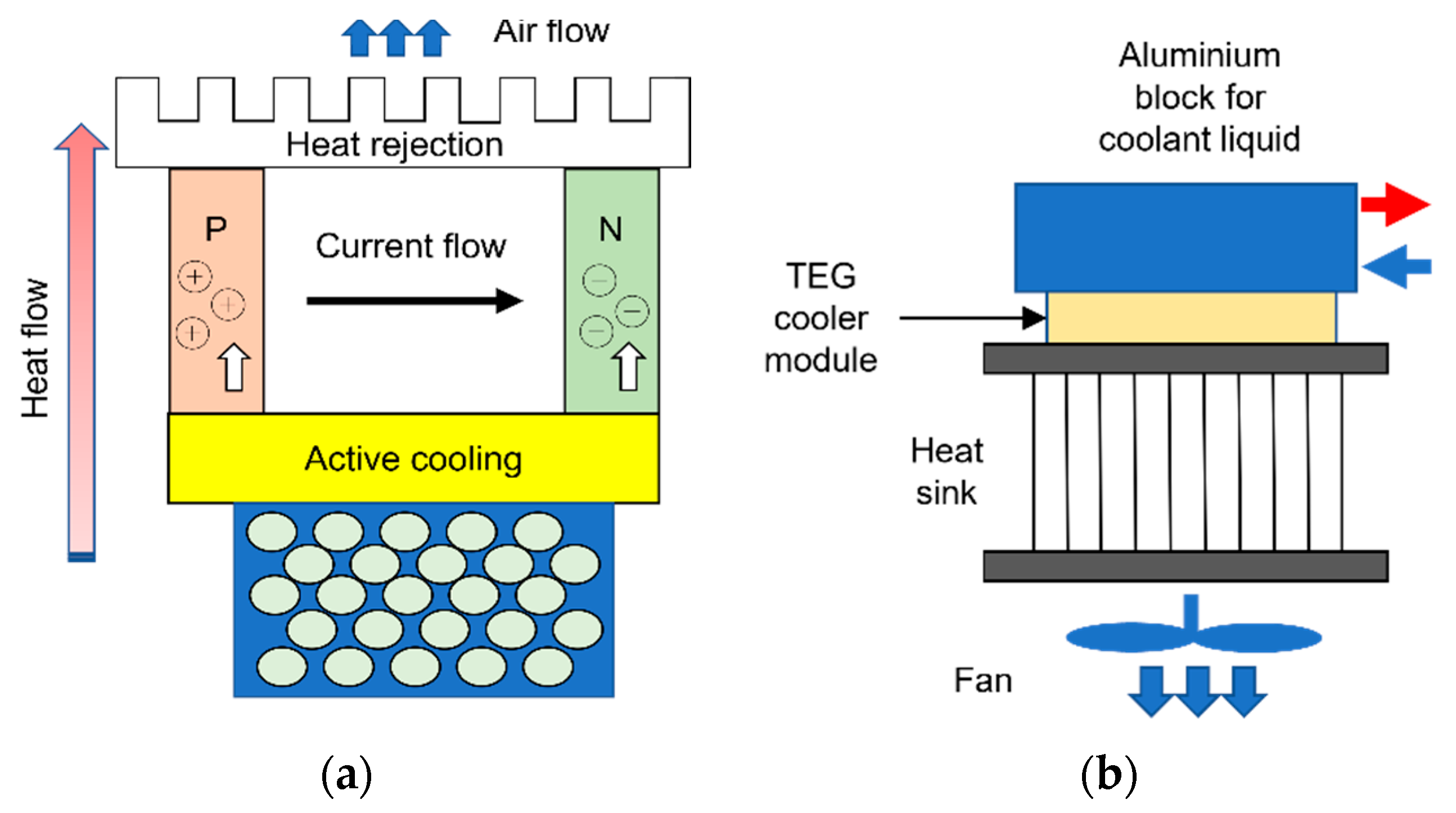
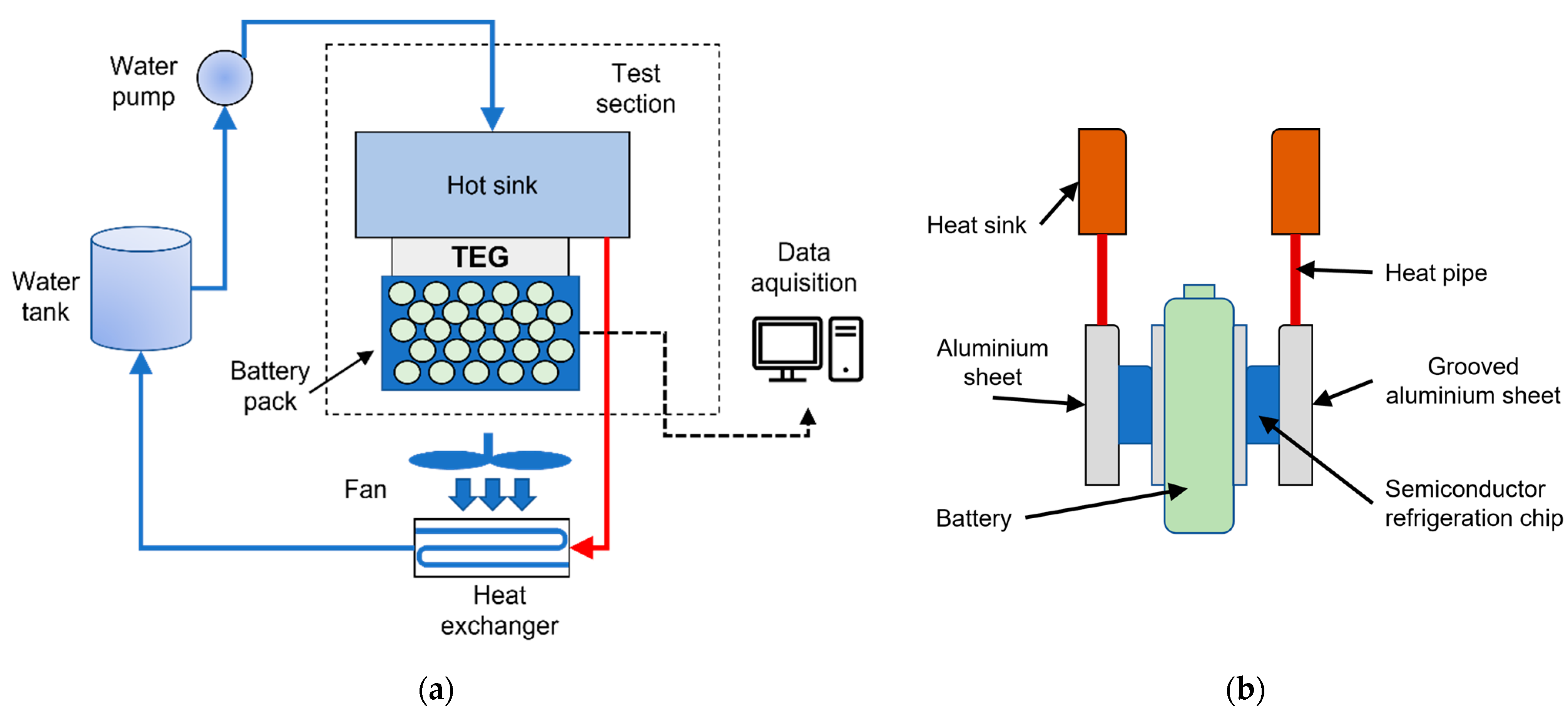
  • TEC + others.
A first meaningful discussion is regarding the advantages and disadvantages of each individual element that can be used in BTMSs, being it passive or active, listed in Table 1. Further, the characteristics regarding their implementation in BTMSs and adaptability to the different battery shapes are detailed in Table 2. The disadvantages of basic BTMSs are reduced through combining them with other systems into hybrid BTMSs, presented in Table 3 and Table 4, or various other methods.
Air cooling represents the most easily applicable solution for the thermal management of batteries. However, the low specific heat of air still is a major concern when considering its application in full-size battery packs. A possible solution could be the use of active cooling and heating, using an evaporator or heater core. This would allow a reduced dependency on ambient conditions, an increased control over the inlet temperature in the battery pack and therefore a more efficient management of the temperatures inside the pack. Although such a method would increase the heat transfer, the occupied large volume still represents a significant disadvantage. The inlet and outlet scheme and the air flow configuration are also promising research directions, with numerous possible combinations. However, the possibility of implementing these schemes in a full-size battery pack should also be investigated, considering the need to implement the required inlet and outlet channels in the tight package of a vehicle. Regarding the uneven temperature distribution of air cooling, this can be reduced by using air flow channels with variable widths or by distribution pipes.
The large use of prismatic and pouch batteries in commercial vehicles means that liquid cooling plates are one of the most implemented cooling systems in electric vehicles, due to their good heat capacity and compact arrangement. Most research studies focus on various parameters regarding heat transfer and pressure drop, but only a few consider the uneven heat generation in the batteries, which is even more significant for the larger prismatic and pouch batteries. Therefore, more attention in future studies should be accorded to the possibility of implementing bidirectional or reciprocating liquid flows, considering the local heat generation, therefore improving the temperature distribution. In the presented study, examples of improving the temperature uniformity offered by cooling plates are presented using double-layered plates and a better mass distribution in the channels. The heat transfer capacity of conventional liquid cooling systems can further be enhanced using PCM emulsions or liquid metal. For cylindrical batteries, the poor adaptability to indirect liquid cooling is represented by the use of wavy channels, half helical ducts or conduction elements, which significantly increase complexity and add weight to the system.
Adapting the existing refrigerant circuit of the vehicles to serve also for the thermal management of batteries is a concept with a relatively high probability of practical application. The presented studies clearly show the potential of such systems, having a high heat transfer capacity, a capability to cool below ambient temperature and the possibility of heating. Despite these advantages, there are no mentioned studies to analyze the sizing of such a system for a full-size battery pack, nor the necessary changes to the existing air conditioning system to cope with the additional thermal load of the battery. More effort should be directed towards the development of a large-scale system, with precise control algorithms for cabin comfort, battery maximum temperature and temperature uniformity.
The main disadvantages of pure PCMs, namely the low thermal conductivity and leakage problems can be tackled by adding other materials such as EG, AlN, nanosilica, copper mesh foam and others, to form CPCMs. Although the enhancement of pure PCM with additional materials in different concentrations is a promising research direction, the preparation processes are very laborious, as well as time and energy consuming. It could be of interest by how much the preparation of large quantities of CPCM increases the overall costs of full-size battery packs. Moreover, in the case of pouring hot, melted CPCM directly around the batteries, further investigations are needed regarding the possible negative effects on Li-ion batteries.
Another disadvantage, the limited capacity of storing thermal energy as latent heat, represented by the complete melting of PCM, can be solved by coupling with air or liquid cooling for a better heat dissipation and recovery of the PCM. At present, the main reasons that stop the large-scale applicability of PCMs are the leakage problems, with a negative impact on the safety and reliability of the system and the high additional mass.
Heat pipes coupled with air, water, or refrigerant cooling present good heat transfer efficiency due to the excellent thermal conductivity of HPs, but to also obtain temperature uniformity, it is possible to further add PCM. Research regarding alternative materials in the construction of heat pipes should be closely followed. The possible replacement of copper with aluminum would significantly reduce the costs and could also save some weight, but more investigations in this direction are necessary to determine by how much would the thermal conductivity be affected.
The low COP of TECs means that they are usually used as a supporting device to existing BTMSs, with the advantages of high cooling capacity and possibility of heating. A BTMS using only TEC could be applicable after a significant increase of the energy efficiency of these. In order to be economically competitive with other systems, the thermoelectric figure of merit should increase approximately three times, which for the moment is only possible by using sophisticated and expensive nanostructures.
Both HPs and TECs increase the overall costs of the system, slowing down their large-scale applicability in electric-driven vehicles. However, the use of cheaper alternative materials in the construction of these components could result in an intensified interest in HP-based and TEC-based BTMSs.
The results and good practices obtained so far in the design, configuration and development of BTMSs for Li-ion batteries can further become a starting point for studies related to the thermal management of fuel cells. It is well known that at least at European level the massive use of hydrogen for the supply of electricity is desired in future years, with the help of technologies based on fuel cells for electricity generation.
The general conclusion that can be issued is that considering the great variety of types, design and approaches regarding BTMSs, researchers in this field must pay attention to future research and developments in this domain. Applying and integrating the proposed novelty systems and models could improve the thermal and energy efficiency of full-size battery packs.

Author Contributions

Conceptualization, T.I.C.B. and F.M.; methodology, T.I.C.B.; validation, T.I.C.B. and F.M.; formal analysis, T.I.C.B. and F.M.; investigation, T.I.C.B.; writing—original draft preparation, T.I.C.B. and F.M.; writing—review and editing, T.I.C.B. and F.M.; supervision, F.M. All authors have read and agreed to the published version of the manuscript.

Funding

This research received no external funding.

Institutional Review Board Statement

Not applicable.

Informed Consent Statement

Not applicable.

Conflicts of Interest

The authors declare no conflict of interest.

References

  1. Climate Strategies & Targets. Available online: https://ec.europa.eu/clima/policies/strategies_en (accessed on 22 April 2021).
  2. EU Climate Action and the European Green Deal. Available online: https://ec.europa.eu/clima/policies/eu-climate-action_en (accessed on 22 April 2021).
  3. Fernandez Pales, A.; Bouckaert, S.; Abergel, T.; Goodson, T. Net Zero by 2050 Hinges on a Global Push to Increase Energy Efficiency; International Energy Agency, France, May 2021. Available online: https://www.iea.org/reports/net-zero-by-2050. (accessed on 8 June 2021).
  4. Aneke, M.; Wang, M. Energy storage technologies and real life applications—A state of the art review. Appl. Energy 2016, 179, 350–377. [Google Scholar] [CrossRef] [Green Version]
  5. Bukhari, S.; Maqsood, J.; Baig, M.Q.; Ashraf, S.; Khan, T.A. Comparison of Characteristics–Lead Acid, Nickel Based, Lead Crystal and Lithium Based Batteries. In Proceedings of the 17th UKSim-AMSS International Conference on Modelling and Simulation (UKSim), Cambridge, UK, 25–27 March 2015; pp. 444–450. [Google Scholar]
  6. Naik, I.; Nandgaonkar, M. Review of the approaches and modeling methodology for lithium-ion battery thermal management sustems for electric vehicles. In Advances in Material and Mechanicsl Engineering, Select Proceedings of ICFTMME 2020; Pandey, C., Goyat, V., Goel, S., Eds.; Springer Nature Singapore Pte Ltd.: Singapore, 2021; pp. 75–112. [Google Scholar] [CrossRef]
  7. Spitthoff, L.; Shearing, P.R.; Burheim, O.S. Temperature, Ageing and Thermal Management of Lithium-Ion Batteries. Energies 2021, 14, 1248. [Google Scholar] [CrossRef]
  8. Bandhauer, T.M.; Garimella, S.; Fuller, T.F. A critical review of thermal issues in lithium-ion batteries. J. Electrochem. Soc. 2011, 15, 1–25. [Google Scholar] [CrossRef]
  9. Ianniciello, L.; Biwolé, P.H.; Achard, P. Electric vehicles batteries thermal management systems employing phase change materials. J. Power Sources 2018, 378, 383–403. [Google Scholar] [CrossRef]
  10. Ma, S.; Jiang, M.; Tao, P.; Song, C.; Wu, J.; Wang, J.; Deng, T.; Shang, W. Temperature effect and thermal impact in lithium-ion batteries: A review. Prog. Nat. Sci. Mater. Int. 2018, 28, 653–666. [Google Scholar] [CrossRef]
  11. Goutam, S.; Timmermans, J.M.; Omar, N.; Van den Bossche, P.; Van Mierlo, J. Comparative study of surface temperature behavior of commercial li-ion pouch cells of different chemistries and capacities by infrared thermography. Energies 2015, 8, 8175–8192. [Google Scholar] [CrossRef] [Green Version]
  12. Buchmann, I. Battery University. Available online: https://batteryuniversity.com/ (accessed on 12 May 2021).
  13. Kitoh, K.; Nemoto, H. 100 Wh large size Li-ion batteries and safety tests. J. Power Sources 1999, 81–82, 887–890. [Google Scholar] [CrossRef]
  14. Ramadass, P.; Haran, B.; White, R.; Popov, B.N. Capacity fade of Sony 18650 cells cycled at elevated temperatures: Part I. Cycling performance. J. Power Sources 2002, 112, 606–613. [Google Scholar] [CrossRef] [Green Version]
  15. Rugh, J.P.; Pesaran, A.; Smith, K. Electric Vehicle Battery Thermal Issues and Thermal Management Techniques (Presentation); NREL (National Renewable Energy Laboratory): Golden, CO, USA, 2011. [Google Scholar]
  16. Zhao, R.; Gu, J.; Liu, J. An experimental study of heat pipe thermal management system with wet cooling method for lithium ion batteries. J. Power Sources 2015, 273, 1089–1097. [Google Scholar] [CrossRef]
  17. Pesaran, A.A. Battery thermal models for hybrid vehicle simulations. J. Power Sources 2002, 110, 377–382. [Google Scholar] [CrossRef]
  18. Jaguemont, J.; Boulon, L.; Dube, Y.; Martel, F. Thermal Management of a Hybrid Electric Vehicle in Cold Weather. IEEE Trans. Energy Convers. 2016, 31, 1110–1120. [Google Scholar] [CrossRef]
  19. Peng, X.; Chen, S.; Garg, A.; Bao, N.; Panda, B. A review of the estimation and heating methods for lithium-ion batteries pack at the cold environment. Energy Sci. Eng. 2019, 7, 645–662. [Google Scholar] [CrossRef] [Green Version]
  20. Jeffs, J.; Dinh, T.Q.; Widanage, W.D.; McGordon, A.; Picarelli, A. Optimisation of Direct Battery Thermal Management for EVs Operating in Low-Temperature Climates. Energies 2020, 13, 5980. [Google Scholar] [CrossRef]
  21. Raza, W.; Ko, G.S.; Park, Y.C. Induction heater based battery thermal management system for electric vehicles. Energies 2020, 13, 5711. [Google Scholar] [CrossRef]
  22. Zhong, G.; Zhang, G.; Yang, X.; Li, X.; Wang, Z.; Yang, C.; Yang, C.; Gao, G. Researches of composite phase change material cooling / resistance wire preheating coupling system of a designed 18650-type battery module. Appl. Therm. Eng. 2017, 127, 176–183. [Google Scholar] [CrossRef]
  23. Jaguemont, J.; Omar, N.; Abdel-Monem, M.; Van den Bossche, P.; Van Mierlo, J. Fast-charging investigation on high-power and high-energy density pouch cells with 3D-thermal model development. Appl. Therm. Eng. 2018, 128, 1282–1296. [Google Scholar] [CrossRef]
  24. Wang, Q.; Jiang, B.; Li, B.; Yan, Y. A critical review of thermal management models and solutions of lithium-ion batteries for the development of pure electric vehicles. Renew. Sustain. Energy Rev. 2016, 64, 106–128. [Google Scholar] [CrossRef]
  25. Jaguemont, J.; Boulon, L.; Dubé, Y. A comprehensive review of lithium-ion batteries used in hybrid and electric vehicles at cold temperatures. Appl. Energy 2016, 164, 99–114. [Google Scholar] [CrossRef]
  26. de Hoog, J.; Jaguemont, J.; Abdel-Monem, M.; Van Den Bossche, P.; Van Mierlo, J.; Omar, N. Combining an Electrothermal and Impedance Aging Model to Investigate Thermal Degradation Caused by Fast Charging. Energies 2018, 11, 804. [Google Scholar] [CrossRef] [Green Version]
  27. Hammami, A.; Raymond, N.; Armand, M. Lithium-ion batteries: Runaway risk of forming toxic compounds. Nature 2003, 424, 635–636. [Google Scholar] [CrossRef]
  28. Kim, J.; Oh, J.; Lee, H. Review on battery thermal management system for electric vehicles. Appl. Therm. Eng. 2019, 149, 192–212. [Google Scholar] [CrossRef]
  29. Cai, H.; Xu, C.; Liao, Y.; Su, L.; Weng, Z. Mass maldistribution research of different internal flowing channels in the cooling plate applied to electric vehicle batteries. Appl. Sci. 2019, 9, 636. [Google Scholar] [CrossRef] [Green Version]
  30. Han, X.; Lu, L.; Zheng, Y.; Feng, X.; Li, Z.; Li, J.; Ouyang, M. A review on the key issues of the lithium ion battery degradation among the whole life cycle. eTransportation 2019, 1, 100005. [Google Scholar] [CrossRef]
  31. Larsson, F.; Mellander, B.-E. Abuse by External Heating, Overcharge and Short Circuiting of Commercial Lithium-Ion Battery Cells. J. Electrochem. Soc. 2014, 161, A1611–A1617. [Google Scholar] [CrossRef]
  32. Feng, X.; Zheng, S.; Ren, D.; He, X.; Wang, L.; Cui, H.; Liu, X.; Jin, C.; Zhang, F.; Xu, C.; et al. Investigating the thermal runaway mechanisms of lithium-ion batteries based on thermal analysis database. Appl. Energy 2019, 246, 53–64. [Google Scholar] [CrossRef]
  33. Lu, L.; Han, X.; Li, J.; Hua, J.; Ouyang, M. A review on the key issues for lithium-ion battery management in electric vehicles. J. Power Sources 2013, 226, 272–288. [Google Scholar] [CrossRef]
  34. Iraola, U.; Aizpuru, I.; Gorrotxategi, I.; Segade, J.M.C.; Larrazabal, A.E.; Gil, I. Influence of voltage balancing on the temperature distribution of a li-ion battery module. IEEE Trans. Energy Convers. 2015, 30, 507–514. [Google Scholar] [CrossRef]
  35. Feng, X.; Xu, C.; He, X.; Wang, L.; Zhang, G.; Ouyang, M. Mechanisms for the evolution of cell variations within a LiNixCoyMnzO2/graphite lithium-ion battery pack caused by temperature non-uniformity. J. Clean. Prod. 2018, 205, 447–462. [Google Scholar] [CrossRef]
  36. Kuper, C.; Hoh, M.; Houchin-Miller, G.; Fuhr, J. Thermal management of hybrid vehicle battery systems. In Proceedings of the 24th International Battery, Hybrid and Fuel Cell Electric Vehicle Conference and Exhibition (EVS-24), Stavanger, Norway, 13−16 May 2009; pp. 1–10. [Google Scholar]
  37. Pesaran, A.A. Battery Thermal Management in EVs and HEVs: Issues and Solutions. In Proceedings of the Advanced Automotive Battery Conference, Las Vegas, Nevada, USA, 6−8 February 2001; pp. 10–20. [Google Scholar]
  38. Ouyang, D.; Chen, M.; Huang, Q.; Weng, J.; Wang, Z.; Wang, J. A Review on the thermal hazards of the lithium-ion battery and the corresponding countermeasures. Appl. Sci. 2019, 9, 2483. [Google Scholar] [CrossRef] [Green Version]
  39. Wu, W.; Wang, S.; Wu, W.; Chen, K.; Hong, S.; Lai, Y. A critical review of battery thermal performance and liquid based battery thermal management. Energy Convers. Manag. 2019, 182, 262–281. [Google Scholar] [CrossRef]
  40. Abdel-Monem, M.; Trad, K.; Omar, N.; Hegazy, O.; Van den Bossche, P.; Van Mierlo, J. Influence analysis of static and dynamic fast-charging current profiles on ageing performance of commercial lithium-ion batteries. Energy 2017, 120, 179–191. [Google Scholar] [CrossRef]
  41. Mahmoudzadeh Andwari, A.; Pesiridis, A.; Rajoo, S.; Martinez-Botas, R.; Esfahanian, V. A review of Battery Electric Vehicle technology and readiness levels. Renew. Sustain. Energy Rev. 2017, 78, 414–430. [Google Scholar] [CrossRef]
  42. Hémery, C.-V. Study of Thermal Phenomena in Li-Ion Batteries; Université de Grenoble: Grenoble, France, 2013. [Google Scholar]
  43. Bernardi, D.; Pawlikowski, E.; Newman, J. General energy balance for battery systems. J. Electrochem. Soc. 1985, 132, 1152. [Google Scholar] [CrossRef] [Green Version]
  44. Heubner, C.; Schneider, M.; Lämmel, C.; Michaelis, A. Local heat generation in a single stack lithium ion battery cell. Electrochim. Acta 2015, 186, 404–412. [Google Scholar] [CrossRef]
  45. Nazari, A.; Farhad, S. Heat generation in lithium-ion batteries with different nominal capacities and chemistries. Appl. Therm. Eng. 2017, 125, 1501–1517. [Google Scholar] [CrossRef]
  46. Thakur, A.K.; Prabakaran, R.; Elkadeem, M.R.; Sharshir, S.W.; Arıcı, M.; Wang, C.; Zhao, W.; Hwang, J.Y.; Saidur, R. A state of art review and future viewpoint on advance cooling techniques for Lithium–ion battery system of electric vehicles. J. Energy Storage 2020, 32, 101771. [Google Scholar] [CrossRef]
  47. Surya, S.; Marcis, V.; Williamson, S. Core Temperature Estimation for a Lithium ion 18650 Cell. Energies 2020, 14, 87. [Google Scholar] [CrossRef]
  48. Drake, S.J.; Martin, M.; Wetz, D.A.; Ostanek, J.K.; Miller, S.P.; Heinzel, J.M.; Jain, A. Heat generation rate measurement in a Li-ion cell at large C-rates through temperature and heat flux measurements. J. Power Sources 2015, 285, 266–273. [Google Scholar] [CrossRef]
  49. Hong, J.; Maleki, H.; Al Hallaj, S.; Redey, L.; Selman, J.R. Electrochemical-Calorimetric Studies of Lithium-Ion Cells. J. Electrochem. Soc. 1998, 145, 1489–1501. [Google Scholar] [CrossRef]
  50. Kobayashi, Y.; Miyashiro, H.; Kumai, K.; Takei, K.; Iwahori, T.; Uchida, I. Precise Electrochemical Calorimetry of LiCoO[sub 2]/Graphite Lithium-Ion Cell. J. Electrochem. Soc. 2002, 149, A978. [Google Scholar] [CrossRef]
  51. Drake, S.J.; Wetz, D.A.; Ostanek, J.K.; Miller, S.P.; Heinzel, J.M.; Jain, A. Measurement of anisotropic thermophysical properties of cylindrical Li-ion cells. J. Power Sources 2014, 252, 298–304. [Google Scholar] [CrossRef]
  52. Dinçer, I.; Hamut, H.; Javani, N. Thermal Management of Electric Vehicle Battery Systems; John Wiley and Sons Ltd.: Hoboken, NJ, USA, 2017. [Google Scholar]
  53. Siddique, A.R.M.; Mahmud, S.; Heyst, B. Van A comprehensive review on a passive (phase change materials) and an active (thermoelectric cooler) battery thermal management system and their limitations. J. Power Sources 2018, 401, 224–237. [Google Scholar] [CrossRef]
  54. Jaguemont, J.; Van Mierlo, J. A comprehensive review of future thermal management systems for battery-electrified vehicles. J. Energy Storage 2020, 31, 101551. [Google Scholar] [CrossRef]
  55. Zhao, C.; Zhang, B.; Zheng, Y.; Huang, S.; Yan, T.; Liu, X. Hybrid Battery Thermal Management System in Electrical Vehicles: A Review. Energies 2020, 13, 6257. [Google Scholar] [CrossRef]
  56. Zhou, H.; Zhou, F.; Xu, L.; Kong, J. Thermal performance of cylindrical Lithium-ion battery thermal management system based on air distribution pipe. Int. J. Heat Mass Transf. 2019, 131, 984–998. [Google Scholar] [CrossRef]
  57. Liu, Y.; Zhang, J. Design a J-type air-based battery thermal management system through surrogate-based optimization. Appl. Energy 2019, 252, 113426. [Google Scholar] [CrossRef]
  58. Jilte, R.D.; Kumar, R.; Ma, L. Thermal performance of a novel confined flow Li-ion battery module. Appl. Therm. Eng. 2019, 146, 1–11. [Google Scholar] [CrossRef]
  59. Wu, M.S.; Liu, K.H.; Wang, Y.Y.; Wan, C.C. Heat dissipation design for lithium-ion batteries. J. Power Sources 2002, 109, 160–166. [Google Scholar] [CrossRef]
  60. Peng, X.; Cui, X.; Liao, X.; Garg, A. A Thermal Investigation and Optimization of an Air-Cooled Lithium-Ion Battery Pack. Energies 2020, 13, 2956. [Google Scholar] [CrossRef]
  61. Chen, K.; Chen, Y.; She, Y.; Song, M.; Wang, S.; Chen, L. Construction of effective symmetrical air-cooled system for battery thermal management. Appl. Therm. Eng. 2020, 166, 114679. [Google Scholar] [CrossRef]
  62. Li, X.; He, F.; Zhang, G.; Huang, Q.; Zhou, D. Experiment and simulation for pouch battery with silica cooling plates and copper mesh based air cooling thermal management system. Appl. Therm. Eng. 2019, 146, 866–880. [Google Scholar] [CrossRef]
  63. Hakeem, A.A.A.; Solyali, D. Empirical thermal performance investigation of a compact lithium ion battery module under forced convection cooling. Appl. Sci. 2020, 10, 3732. [Google Scholar] [CrossRef]
  64. Wang, S.; Li, K.; Tian, Y. Improved thermal performance of a large laminated lithium-ion power battery by reciprocating air flow. Appl. Therm. Eng. 2019, 152, 445–454. [Google Scholar] [CrossRef]
  65. Zhang, J.; Wu, X.; Chen, K.; Zhou, D.; Song, M. Experimental and numerical studies on an efficient transient heat transfer model for air-cooled battery thermal management systems. J. Power Sources 2021, 490, 229539. [Google Scholar] [CrossRef]
  66. Wang, M.; Hung, T.-C.; Xi, H. Numerical Study on Performance Enhancement of the Air-Cooled Battery Thermal Management System by Adding Parallel Plates. Energies 2021, 14, 3096. [Google Scholar] [CrossRef]
  67. Fan, Y.; Bao, Y.; Ling, C.; Chu, Y.; Tan, X.; Yang, S. Experimental study on the thermal management performance of air cooling for high energy density cylindrical lithium-ion batteries. Appl. Therm. Eng. 2019, 155, 96–109. [Google Scholar] [CrossRef]
  68. Lai, Y.; Wu, W.; Chen, K.; Wang, S.; Xin, C. A compact and lightweight liquid-cooled thermal management solution for cylindrical lithium-ion power battery pack. Int. J. Heat Mass Transf. 2019, 144, 118581. [Google Scholar] [CrossRef]
  69. Chen, D.; Jiang, J.; Kim, G.H.; Yang, C.; Pesaran, A. Comparison of different cooling methods for lithium ion battery cells. Appl. Therm. Eng. 2016, 94, 846–854. [Google Scholar] [CrossRef] [Green Version]
  70. Lv, Y.; Zhou, D.; Yang, X.; Liu, X.; Li, X.; Zhang, G. Experimental investigation on a novel liquid-cooling strategy by coupling with graphene-modi fi ed silica gel for the thermal management of cylindrical battery. Appl. Therm. Eng. 2019, 159, 113885. [Google Scholar] [CrossRef]
  71. Giuliano, M.R.; Prasad, A.K.; Advani, S.G. Experimental study of an air-cooled thermal management system for high capacity lithium–titanate batteries. J. Power Sources 2012, 216, 345–352. [Google Scholar] [CrossRef]
  72. Panchal, S.; Khasow, R.; Dincer, I.; Agelin-Chaab, M.; Fraser, R.; Fowler, M. Thermal design and simulation of mini-channel cold plate for water cooled large sized prismatic lithium-ion battery. Appl. Therm. Eng. 2017, 122, 80–90. [Google Scholar] [CrossRef]
  73. Shang, Z.; Qi, H.; Liu, X.; Ouyang, C.; Wang, Y. Structural optimization of lithium-ion battery for improving thermal performance based on a liquid cooling system. Int. J. Heat Mass Transf. 2019, 130, 33–41. [Google Scholar] [CrossRef]
  74. Ye, B.; Rubel, M.R.H.; Li, H. Design and optimization of cooling plate for battery module of an electric vehicle. Appl. Sci. 2019, 9, 754. [Google Scholar] [CrossRef] [Green Version]
  75. Monika, K.; Chakraborty, C.; Roy, S.; Dinda, S.; Singh, S.A.; Datta, S.P. An improved mini-channel based liquid cooling strategy of prismatic LiFePO4 batteries for electric or hybrid vehicles. J. Energy Storage 2021, 35, 102301. [Google Scholar] [CrossRef]
  76. Patil, M.S.; Seo, J.H.; Panchal, S.; Jee, S.W.; Lee, M.Y. Investigation on thermal performance of water-cooled Li-ion pouch cell and pack at high discharge rate with U-turn type microchannel cold plate. Int. J. Heat Mass Transf. 2020, 155, 119728. [Google Scholar] [CrossRef]
  77. Deng, T.; Ran, Y.; Yin, Y.; Chen, X.; Liu, P. Multi-objective optimization design of double-layered reverting cooling plate for lithium-ion batteries. Int. J. Heat Mass Transf. 2019, 143, 118580. [Google Scholar] [CrossRef]
  78. Amalesh, T.; Narasimhan, N.L. Introducing new designs of minichannel cold plates for the cooling of Lithium-ion batteries. J. Power Sources 2020, 479, 228775. [Google Scholar] [CrossRef]
  79. Shen, M.; Gao, Q. Structure design and effect analysis on refrigerant cooling enhancement of battery thermal management system for electric vehicles. J. Energy Storage 2020, 32, 101940. [Google Scholar] [CrossRef]
  80. Zhang, Y.; Huang, J.; Cao, M.; Du, G.; Liu, Z.; Li, W. Preparation of Boron Nitride and Silicone Rubber Composite Material for Application in Lithium Batteries. Energies 2021, 14, 999. [Google Scholar] [CrossRef]
  81. Dubey, P.; Pulugundla, G.; Srouji, A.K. Direct Comparison of Immersion and Cold-Plate Based Cooling for Automotive Li-Ion Battery Modules. Energies 2021, 14, 1259. [Google Scholar] [CrossRef]
  82. Bhattacharjee, A.; Mohanty, R.; Ghosh, A. Design of an Optimized Thermal Management System for Li-Ion Batteries under Di erent Discharging Conditions. Energies 2020, 13, 5695. [Google Scholar] [CrossRef]
  83. Wang, F.; Cao, J.; Ling, Z.; Zhang, Z.; Fang, X. Experimental and simulative investigations on a phase change material nano-emulsion-based liquid cooling thermal management system for a lithium-ion battery pack. Energy 2020, 207, 118215. [Google Scholar] [CrossRef]
  84. Liu, Z.; Wang, H.; Yang, C.; Zhao, J. Simulation study of lithium-ion battery thermal management system based on a variable flow velocity method with liquid metal. Appl. Therm. Eng. 2020, 179, 115578. [Google Scholar] [CrossRef]
  85. Tang, Z.; Wang, S.; Liu, Z.; Cheng, J. Numerical analysis of temperature uniformity of a liquid cooling battery module composed of heat-conducting blocks with gradient contact surface angles. Appl. Therm. Eng. 2020, 178, 115509. [Google Scholar] [CrossRef]
  86. Zhao, C.; Cao, W.; Dong, T.; Jiang, F. Thermal behavior study of discharging/charging cylindrical lithium-ion battery module cooled by channeled liquid flow. Int. J. Heat Mass Transf. 2018, 120, 751–762. [Google Scholar] [CrossRef]
  87. Zhou, H.; Zhou, F.; Zhang, Q.; Wang, Q.; Song, Z. Thermal management of cylindrical lithium-ion battery based on a liquid cooling method with half-helical duct. Appl. Therm. Eng. 2019, 162, 114257. [Google Scholar] [CrossRef]
  88. Cao, W.; Zhao, C.; Wang, Y.; Dong, T.; Jiang, F. Thermal modeling of full-size-scale cylindrical battery pack cooled by channeled liquid flow. Int. J. Heat Mass Transf. 2019, 138, 1178–1187. [Google Scholar] [CrossRef]
  89. Jiang, Z.Y.; Qu, Z.G. Lithium–ion battery thermal management using heat pipe and phase change material during discharge–charge cycle: A comprehensive numerical study. Appl. Energy 2019, 242, 378–392. [Google Scholar] [CrossRef]
  90. Azizi, Y.; Sadrameli, S.M. Thermal management of a LiFePO 4 battery pack at high temperature environment using a composite of phase change materials and aluminum wire mesh plates. Energy Convers. Manag. 2016, 128, 294–302. [Google Scholar] [CrossRef]
  91. Zhang, J.; Li, X.; Zhang, G.; Wang, Y.; Guo, J.; Wang, Y.; Huang, Q.; Xiao, C.; Zhong, Z. Characterization and experimental investigation of aluminum nitride-based composite phase change materials for battery thermal management. Energy Convers. Manag. 2020, 204, 112319. [Google Scholar] [CrossRef]
  92. Zhang, Z.; Li, Y. Experimental study of a passive thermal management system using copper foam-paraffin composite for lithium ion batteries. Energy Procedia 2017, 142, 2403–2408. [Google Scholar] [CrossRef]
  93. Jiang, G.; Huang, J.; Fu, Y.; Cao, M.; Liu, M. Thermal optimization of composite phase change material / expanded graphite for Li-ion battery thermal management. Appl. Therm. Eng. 2016, 108, 1119–1125. [Google Scholar] [CrossRef]
  94. Wu, W.; Wu, W.; Wang, S. Thermal optimization of composite PCM based large-format lithium-ion battery modules under extreme operating conditions. Energy Convers. Manag. 2017, 153, 22–33. [Google Scholar] [CrossRef]
  95. Talluri, T.; Kim, T.H.; Shin, K.J. Analysis of a battery pack with a phase change material for the extreme temperature conditions of an electrical vehicle. Energies 2020, 13, 507. [Google Scholar] [CrossRef] [Green Version]
  96. Wang, T.; Wang, S.; Luo, R.; Zhu, C.; Akiyama, T.; Zhang, Z. Microencapsulation of phase change materials with binary cores and calcium carbonate shell for thermal energy storage. Appl. Energy 2016, 171, 113–119. [Google Scholar] [CrossRef]
  97. Zhang, X.; Wang, X.; Wu, D. Design and synthesis of multifunctional microencapsulated phase change materials with silver/silica double-layered shell for thermal energy storage, electrical conduction and antimicrobial effectiveness. Energy 2016, 111, 498–512. [Google Scholar] [CrossRef]
  98. Liu, J.; Wang, Q.; Ling, Z.; Fang, X.; Zhang, Z. A novel process for preparing molten salt/expanded graphite composite phase change blocks with good uniformity and small volume expansion. Sol. Energy Mater. Sol. Cells 2017, 169, 280–286. [Google Scholar] [CrossRef]
  99. Chen, M.; Zhang, S.; Wang, G.; Weng, J.; Ouyang, D.; Wu, X.; Zhao, L.; Wang, J. Experimental analysis on the thermal management of lithium-ion batteries based on phase change materials. Appl. Sci. 2020, 10, 7354. [Google Scholar] [CrossRef]
  100. Lv, Y.; Situ, W.; Yang, X.; Zhang, G.; Wang, Z. A novel nanosilica-enhanced phase change material with anti-leakage and anti-volume-changes properties for battery thermal management. Energy Convers. Manag. 2018, 163, 250–259. [Google Scholar] [CrossRef]
  101. Liu, Z.; Huang, J.; Cao, M.; Jiang, G.; Yan, Q.; Hu, J. Experimental study on the thermal management of batteries based on the coupling of composite phase change materials and liquid cooling. Appl. Therm. Eng. 2021, 185, 116415. [Google Scholar] [CrossRef]
  102. Huang, Y.; Cheng, W.; Zhao, R. Thermal management of Li-ion battery pack with the application of fl exible form-stable composite phase change materials. Energy Convers. Manag. 2019, 182, 9–20. [Google Scholar] [CrossRef]
  103. Huang, R.; Li, Z.; Hong, W.; Wu, Q.; Yu, X. Experimental and numerical study of PCM thermophysical parameters on lithium-ion battery thermal management. Energy Rep. 2020, 6, 8–19. [Google Scholar] [CrossRef]
  104. Yan, J.; Li, K.; Chen, H.; Wang, Q.; Sun, J. Experimental study on the application of phase change material in the dynamic cycling of battery pack system. Energy Convers. Manag. 2016, 128, 12–19. [Google Scholar] [CrossRef]
  105. Gschwander, S.; Niedermaier, S.; Gamisch, S.; Kick, M.; Klünder, F.; Haussmann, T. Storage capacity in dependency of supercooling and cycle stability of different pcm emulsions. Appl. Sci. 2021, 11, 3612. [Google Scholar] [CrossRef]
  106. Weng, J.; Yang, X.; Zhang, G.; Ouyang, D.; Chen, M.; Wang, J. Optimization of the detailed factors in a phase-change-material module for battery thermal management. Int. J. Heat Mass Transf. 2019, 138, 126–134. [Google Scholar] [CrossRef]
  107. Jilte, R.D.; Kumar, R.; Ahmadi, M.H.; Chen, L. Battery thermal management system employing phase change material with cell-to-cell air cooling. Appl. Therm. Eng. 2019, 161, 114199. [Google Scholar] [CrossRef]
  108. Nasehi, R.; Alamatsaz, A.; Salimpour, M.R. Using multi-shell phase change materials layers for cooling a lithium-ion battery. Therm. Sci. 2016, 20, 391–403. [Google Scholar] [CrossRef]
  109. Yan, J.; Wang, Q.; Li, K.; Sun, J. Numerical study on the thermal performance of a composite board in battery thermal management system. Appl. Therm. Eng. 2016, 106, 131–140. [Google Scholar] [CrossRef]
  110. Ling, Z.; Wen, X.; Zhang, Z.; Fang, X.; Gao, X. Thermal management performance of phase change materials with different thermal conductivities for Li-ion battery packs operated at low temperatures. Energy 2018, 144, 977–983. [Google Scholar] [CrossRef]
  111. Faghri, A. Heat Pipe Science & Technology; Taylor & Francis Group: Abingdon, UK, 1995. [Google Scholar]
  112. Behi, H.; Karimi, D.; Behi, M.; Jaguemont, J.; Ghanbarpour, M.; Behnia, M.; Berecibar, M.; Van Mierlo, J. Thermal management analysis using heat pipe in the high current discharging of lithium-ion battery in electric vehicles. J. Energy Storage 2020, 32, 101893. [Google Scholar] [CrossRef]
  113. Zhang, Z.; Wei, K. Experimental and numerical study of a passive thermal management system using flat heat pipes for lithium-ion batteries. Appl. Therm. Eng. 2020, 166, 114660. [Google Scholar] [CrossRef]
  114. Kleiner, J.; Singh, R.; Schmid, M.; Komsiyska, L.; Elger, G.; Endisch, C. Influence of heat pipe assisted terminal cooling on the thermal behavior of a large prismatic lithium-ion cell during fast charging in electric vehicles. Appl. Therm. Eng. 2021, 188, 116328. [Google Scholar] [CrossRef]
  115. Liu, F.; Lan, F.; Chen, J. Dynamic thermal characteristics of heat pipe via segmented thermal resistance model for electric vehicle battery cooling. J. Power Sources 2016, 321, 57–70. [Google Scholar] [CrossRef]
  116. Chen, M.; Li, J. Nanofluid-based pulsating heat pipe for thermal management of lithium-ion batteries for electric vehicles. J. Energy Storage 2020, 32, 101715. [Google Scholar] [CrossRef]
  117. Wei, A.; Qu, J.; Qiu, H.; Wang, C.; Cao, G. Heat transfer characteristics of plug-in oscillating heat pipe with binary-fluid mixtures for electric vehicle battery thermal management. Int. J. Heat Mass Transf. 2019, 135, 746–760. [Google Scholar] [CrossRef]
  118. Ling, Z.; Wang, F.; Fang, X.; Gao, X.; Zhang, Z. A hybrid thermal management system for lithium ion batteries combining phase change materials with forced-air cooling. Appl. Energy 2015, 148, 403–409. [Google Scholar] [CrossRef] [Green Version]
  119. Molaeimanesh, G.R.; Mirfallah Nasiry, S.M.; Dahmardeh, M. Impact of configuration on the performance of a hybrid thermal management system including phase change material and water-cooling channels for Li-ion batteries. Appl. Therm. Eng. 2020, 181, 116028. [Google Scholar] [CrossRef]
  120. Bai, F.; Chen, M.; Song, W.; Feng, Z.; Li, Y.; Ding, Y. Thermal management performances of PCM/water cooling-plate using for lithium-ion battery module based on non-uniform internal heat source. Appl. Therm. Eng. 2017, 126, 17–27. [Google Scholar] [CrossRef]
  121. Song, L.; Zhang, H.; Yang, C. Thermal analysis of conjugated cooling configurations using phase change material and liquid cooling techniques for a battery module. Int. J. Heat Mass Transf. 2019, 133, 827–841. [Google Scholar] [CrossRef]
  122. Zhao, Y.; Zou, B.; Li, C.; Ding, Y. Active cooling based battery thermal management using composite phase change materials. Energy Procedia 2019, 158, 4933–4940. [Google Scholar] [CrossRef]
  123. Feng, L.; Zhou, S.; Li, Y.; Wang, Y.; Zhao, Q.; Luo, C.; Wang, G.; Yan, K. Experimental investigation of thermal and strain management for lithium-ion battery pack in heat pipe cooling. J. Energy Storage 2018, 16, 84–92. [Google Scholar] [CrossRef]
  124. Ye, X.; Zhao, Y.; Quan, Z. Experimental study on heat dissipation for lithium-ion battery based on micro heat pipe array (MHPA). Appl. Therm. Eng. 2018, 130, 74–82. [Google Scholar] [CrossRef]
  125. Tran, T.H.; Harmand, S.; Desmet, B.; Filangi, S. Experimental investigation on the feasibility of heat pipe cooling for HEV/EV lithium-ion battery. Appl. Therm. Eng. 2014, 63, 551–558. [Google Scholar] [CrossRef]
  126. Wang, J.; Gan, Y.; Liang, J.; Tan, M.; Li, Y. Sensitivity analysis of factors influencing a heat pipe-based thermal management system for a battery module with cylindrical cells. Appl. Therm. Eng. 2019, 151, 475–485. [Google Scholar] [CrossRef]
  127. Yuan, X.; Tang, A.; Shan, C.; Liu, Z.; Li, J. Experimental investigation on thermal performance of a battery liquid cooling structure coupled with heat pipe. J. Energy Storage 2020, 32, 101984. [Google Scholar] [CrossRef]
  128. Gan, Y.; He, L.; Liang, J.; Tan, M.; Xiong, T.; Li, Y. A numerical study on the performance of a thermal management system for a battery pack with cylindrical cells based on heat pipes. Appl. Therm. Eng. 2020, 179, 115740. [Google Scholar] [CrossRef]
  129. Alihosseini, A.; Shafaee, M. Experimental study and numerical simulation of a Lithium-ion battery thermal management system using a heat pipe. J. Energy Storage 2021, 39, 102616. [Google Scholar] [CrossRef]
  130. Liang, J.; Gan, Y.; Li, Y.; Tan, M.; Wang, J. Thermal and electrochemical performance of a serially connected battery module using a heat pipe-based thermal management system under different coolant temperatures. Energy 2019, 189, 116233. [Google Scholar] [CrossRef]
  131. Yao, M.; Gan, Y.; Liang, J.; Dong, D.; Ma, L.; Liu, J.; Luo, Q.; Li, Y. Performance simulation of a heat pipe and refrigerant-based lithium-ion battery thermal management system coupled with electric vehicle air-conditioning. Appl. Therm. Eng. 2021, 191, 116878. [Google Scholar] [CrossRef]
  132. Zhao, J.; Lv, P.; Rao, Z. Experimental study on the thermal management performance of phase change material coupled with heat pipe for cylindrical power battery pack. Exp. Therm. Fluid Sci. 2017, 82, 182–188. [Google Scholar] [CrossRef]
  133. Huang, Q.; Li, X.; Zhang, G.; Zhang, J.; He, F.; Li, Y. Experimental investigation of the thermal performance of heat pipe assisted phase change material for battery thermal management system. Appl. Therm. Eng. 2018, 141, 1092–1100. [Google Scholar] [CrossRef]
  134. Zhang, W.; Qiu, J.; Yin, X.; Wang, D. A novel heat pipe assisted separation type battery thermal management system based on phase change material. Appl. Therm. Eng. 2020, 165, 114571. [Google Scholar] [CrossRef]
  135. Zhou, H.; Dai, C.; Liu, Y.; Fu, X.; Du, Y. Experimental investigation of battery thermal management and safety with heat pipe and immersion phase change liquid. J. Power Sources 2020, 473, 228545. [Google Scholar] [CrossRef]
  136. Wang, Y.; Peng, P.; Cao, W.; Dong, T.; Zheng, Y.; Lei, B.; Shi, Y. Experimental study on a novel compact cooling system for cylindrical lithium-ion battery module. Appl. Therm. Eng. 2020, 180, 115772. [Google Scholar] [CrossRef]
  137. Wang, Q.; Rao, Z.; Huo, Y.; Wang, S. Thermal performance of phase change material/oscillating heat pipe-based battery thermal management system. Int. J. Therm. Sci. 2016, 102, 9–16. [Google Scholar] [CrossRef]
  138. Godfrey, S. An introduction to thermoelectric coolers. Electron. Cool. 1996, 2, 30–33. [Google Scholar]
  139. Pourkiaei, S.M.; Ahmadi, M.H.; Sadeghzadeh, M.; Moosavi, S.; Pourfayaz, F.; Chen, L.; Pour Yazdi, M.A.; Kumar, R. Thermoelectric cooler and thermoelectric generator devices: A review of present and potential applications, modeling and materials. Energy 2019, 186, 115849. [Google Scholar] [CrossRef]
  140. Maral, Y.; Aktas, M.; Erol, O.; Ongun, R.; Polat, F. An examinaion about thermal capacities of thermoelectric coolers in battery cooling systems. J. Eng. Res. Appl. Sci. 2017, 6, 703–710. [Google Scholar]
  141. Li, X.; Zhong, Z.; Luo, J.; Wang, Z.; Yuan, W.; Zhang, G.; Yang, C.; Yang, C. Experimental Investigation on a Thermoelectric Cooler for Thermal Management of a Lithium-Ion Battery Module. Int. J. Photoenergy 2019, 2019. [Google Scholar] [CrossRef] [Green Version]
  142. Zhang, C.W.; Xu, K.J.; Li, L.Y.; Yang, M.Z.; Gao, H.B.; Chen, S.R. Study on a battery thermal management system based on a thermoelectric effect. Energies 2018, 11, 279. [Google Scholar] [CrossRef] [Green Version]
  143. Lyu, Y.; Siddique, A.R.M.; Majid, S.H.; Biglarbegian, M.; Gadsden, S.A.; Mahmud, S. Electric vehicle battery thermal management system with thermoelectric cooling. Energy Rep. 2019, 5, 822–827. [Google Scholar] [CrossRef]
  144. Song, W.; Bai, F.; Chen, M.; Lin, S.; Feng, Z.; Li, Y. Thermal management of standby battery for outdoor base station based on the semiconductor thermoelectric device and phase change materials. Appl. Therm. Eng. 2018, 137, 203–217. [Google Scholar] [CrossRef] [Green Version]
  145. Jiang, L.; Zhang, H.; Li, J.; Xia, P. Thermal performance of a cylindrical battery module impregnated with PCM composite based on thermoelectric cooling. Energy 2019, 188, 116048. [Google Scholar] [CrossRef]
  146. Zhang, C.; Xia, Z.; Wang, B.; Gao, H.; Chen, S.; Zong, S.; Luo, K. A Li-ion battery thermal management system combining a heat pipe and thermoelectric cooler. Energies 2020, 13, 841. [Google Scholar] [CrossRef] [Green Version]
Figure 1. (a) Schemes for the battery pack with various inlet and outlet number and position (adapted from source [60]); (b) physical layout of a pouch battery using double silica cooling plates with a cooper mesh (adapted from source [62]); (c) schematics of asymmetrical and symmetrical BTMSs (adapted from source [61]).
Energies 14 04879 g001
Figure 2. Schematics of parallel air-cooled BTMSs (a) Z-type 3D (adapted from source [65]); (b) Z-type 2D (adapted from source [65]); (c) U-type 2D (adapted from source [65]); (d) I-type 2D (adapted from source [65]); (e) Z-type with two parallel plates (adapted from source [66]).
Energies 14 04879 g002
Figure 3. Air-based BTMS using distribution pipes (adapted from source [56]).
Energies 14 04879 g003
Figure 4. (a) Optimization of cooling plate serpentine flow channels with splitter blades (adapted from source [29]); (b) schematic of channel connections (adapted from source [79]); (c) mini-channel cold plate designs (adapted from source [78]).
Energies 14 04879 g004
Figure 5. (a) Thermally conductive interface between battery and cold plate (adapted from source [80]); (b) immersion and cold plate cooling (adapted from source [81]).
Energies 14 04879 g005
Figure 6. Liquid cooling BTMSs for cylindrical batteries (a) 3D geometry of the phase change material nano-emulsion-based liquid cooling (adapted from source [83]); (b) structure of liquid-cooled battery pack using liquid metal and copper pipes (adapted from source [84]); (c) schematic diagram and of the graphene oxide-modified silica gel structure with fins-enhanced cooling tubes (adapted from source [70]); (d) structure of the battery with variable surface of the heat conducting block (adapted from source [85]).
Energies 14 04879 g006
Figure 7. Schematics of a battery module cooled using half-helical ducts (adapted from source [87]).
Energies 14 04879 g007
Figure 8. (a) Preparation process of nanosilica-enhanced CPCM (adapted from source [100]); (b) preparation process of CPCM with nano-silver (adapted from source [101]).
Energies 14 04879 g008aEnergies 14 04879 g008b
Figure 9. (a) Experimental setup to measure the performance of different thickness PCM (adapted from source [106]); (b) BTMS employing PCM with cell-to-cell air cooling (adapted from source [107]); (c) multi-shell PCM layers (adapted from source [108]); (d) PCM composite board (adapted from source [109]).
Energies 14 04879 g009
Figure 10. Battery module design with CPCM cooling and a resistance wire wrapped around the batteries (adapted from source [22]).
Energies 14 04879 g010
Figure 11. (a) Passive BTMS using flat heat pipes with fins (adapted from source [113]); (b) thermal cooling of prismatic battery using heat pipe (adapted from source [115]); (c) front and back side of prismatic cell with heat pipe in 8 C discharging rate (adapted from source [112]).
Energies 14 04879 g011
Figure 12. Hybrid BTMSs using PCM coupled with liquid cooling (a) parallel configuration (adapted from source [119]); (b) series 1 configuration (adapted from source [119]); (c) series 2 configuration (adapted from source [119]); (d) parallel/series configuration (adapted from source [119]); (e) different hose connection schemes (adapted from source [101]); (f) cooling plate placed near the electrodes (adapted from source [120]); (g) CPCM with copper foam (adapted from source [122]).
Energies 14 04879 g012
Figure 13. Hybrid BTMSs using heat pipe coupled with air cooling (a) schematic of heat pipe and fin BTMS for cylindrical batteries (adapted from source [123]); (b) battery module with resin matrix and heat pipe (adapted from source [125]).
Energies 14 04879 g013
Figure 14. Hybrid BTMSs using heat pipe coupled with cooling plate (a) L-shaped heat pipe-copper plates and liquid cooling plate (adapted from source [127]); (b) hybrid BTMS consisting L-shaped heat pipes with aluminum sleeves and liquid cooling plate (adapted from source [128]).
Energies 14 04879 g014
Figure 15. Hybrid BTMSs using heat pipe coupled with liquid cooling (a) water channel passing through the condenser section of heat pipes (adapted from source [129]); (b) condenser section in contact with coolant channel (adapted from source [130]).
Energies 14 04879 g015
Figure 16. Hybrid BTMSs using PCM coupled with HP in series configuration (a) PCM assisted by HP and forced convection (adapted from source [132]); (b) HP assisted by PCM and forced convection (adapted from source [134]).
Energies 14 04879 g016
Figure 17. TEC-based hybrid BTMSs (a) TEC combined with forced air cooling (adapted from source [141]); (b) liquid cooling combined with TEC and forced air cooling (adapted from source [143]).
Energies 14 04879 g017
Figure 18. TEC-based hybrid BTMSs (a) PCM coupled with TEC and liquid cooling (adapted from source [144]); (b) TEC coupled with heat pipe and forced convection (adapted from source [146]).
Energies 14 04879 g018
Table 1. Advantages and disadvantages of basic systems used in BTMSs.
System TypeSystem NameAdvantagesDisadvantages
PassivePhase change material
  • Reduced cost
  • Long life cycle
  • High latent heat
  • Stability on a large temperature range
  • Uniform temperature distribution
  • Low thermal conductivity
  • Leakage problems
  • Limited capacity of heat absorption after melting
Heat pipe
  • Very high thermal conductivity
  • Compact
  • No need for maintenance
  • Long life cycle
  • High cost
  • Natural convection of condensation section does not offer satisfactory performance
ActiveAir forced convection
  • Direct contact between the cooling fluid and the batteries
  • Reduced mass
  • Reduced cost
  • Simple structure
  • Easy maintenance
  • Low specific heat
  • Difficult to obtain a uniform flow distribution
  • Non-uniform battery temperature distribution
  • Low efficiency
Liquid withdirect contact (immersion)
  • High thermal conductivity
  • High heat transfer coefficient
  • High mass
  • Possible leakage problems
  • Risk of short circuit
  • Significant pumping losses
Liquid withindirect contact
  • Easier implementation than for direct contact
  • Lower cooling performances than for direct contact
Refrigerant
  • High heat transfer capacity
  • Relatively easy integration in the existing air conditioning system of vehicles
  • Possibility of cooling below ambient temperature
  • Possibility of battery heating
  • Need of over dimensioning the refrigerant circuit to cope with both cabin comfort and battery cooling
Thermoelectric cooler
  • Static device
  • No noise or vibrations
  • Long life cycle
  • Minimum maintenance cost
  • Possibility of cooling below ambient temperature
  • Possibility of battery heating
  • High precision of temperature control
  • Compact
  • Low efficiency
  • High energy consumption
  • High cost
  • Proximity of the device’s hot and cold side
Table 2. System characteristics of basic BTMSs.
System CharacteristicAirLiquid
(direct)
Liquid
(indirect)
RefrigerantPCMCPCMHeat Pipe
Cooling capacityvery smallhighmediumhighvery smallsmallmedium
Temperature
distribution
unevenunevenunevenunevenevenevenuneven
Energy consumptionlowhighmediumhighnonenonenone
Weightlightheavymediummediumheavyheavylight
Sizelargemediumcompactcompactlargelargecompact
Complexitysimplemediumcomplexcomplexmediummediumsimple
Costslowmediummediumhighlowmediumhigh
Possibility of heatingnononoyesnonono
Reliabilityhighmediummediumlowvery lowlowhigh
AdaptabilityCylindricaleasymoderatedifficultdifficulteasyeasydifficult
Prismaticmoderatedifficulteasyeasyeasyeasyeasy
Pouchmoderatedifficulteasyeasymoderatemoderateeasy
Table 3. System characteristics of hybrid BTMSs based on PCM and heat pipe.
System CharacteristicPCM + AirPCM +
Liquid
HP + AirHP +
Liquid
PCM + HP + Air
Cooling capacitymediumhighhighvery highhigh
Temperature
distribution
evenevenunevenuneveneven
Energy consumptionlowmediumlowmediumlow
Weightheavyvery heavylightmediumheavy
Sizelargevery largelargemediumvery large
Complexitymediumcomplexmediumcomplexvery complex
Costsmediumhighhighvery highhigh
Possibility of heatingnonononono
Reliabilitylowvery lowhighmediumlow
AdaptabilityCylindricaleasyeasydifficultdifficulteasy
Prismaticeasyeasyeasymoderateeasy
Pouchmoderatemoderateeasymoderatemoderate
Table 4. System characteristics of hybrid BTMSs based on TEC.
System CharacteristicTEC + AirTEC + Air + LiquidPCM + TEC +
Liquid
TEC + HP + Air
Cooling capacitymediumvery highvery highhigh
Temperature
distribution
unevenunevenevenuneven
Energy consumptionmediumhighhighmedium
Weightlightheavyvery heavymedium
Sizelargelargevery largelarge
Complexitymediumvery complexvery complexcomplex
Costshighvery highvery highvery high
Possibility of heatingyesyesyesyes
Reliabilityhighmediumvery lowhigh
AdaptabilityCylindricaldifficultdifficulteasydifficult
Prismaticeasyeasyeasyeasy
Poucheasyeasymoderateeasy
Publisher’s Note: MDPI stays neutral with regard to jurisdictional claims in published maps and institutional affiliations.

