Abstract
Gas-fired heat pumps are a potential replacement for condensing boilers, utilizing fossil-fuel resources more efficiently and reducing the amount of biogas or hydrogen required in sustainable gas grids. However, their adoption has been limited due to their large size and high capital cost, resulting in long payback times. For adsorption-based heat pumps, the major development challenge is to maximize the rate of heat transfer to the adsorbent, whilst minimizing the thermal mass. This work develops a modular finned-tube carbon–ammonia adsorption generator that incorporates the adsorbent in highly compacted 3-mm layers between aluminum fins. Manufacturing techniques that are amenable to low cost and high-volume production were developed. The module was tested using the large temperature jump (LTJ) method and achieved a time constant for adsorption and desorption of 50 s. The computational model predicted that if incorporated into two adsorption generators of 6 L volume each, they could be used to construct a gas-fired heat pump with a 10 kW heat output and a gas utilization efficiency (GUE, the ratio of useful heat output to higher calorific value of gas used) of 1.2.
1. Introduction
1.1. Gas-Fired Heat Pumps
Fossil fuel boilers providing space heating and domestic hot water production are responsible for a substantial proportion of global carbon dioxide emissions [1,2]. Whilst the ultimate aim may be to replace them with electric heat pumps operating on renewable electricity, for many countries this would require substantial upgrading, or even the complete replacement, of their electrical grids [3]. The problem will be compounded by the increase in electricity demand created by electric vehicles. Gas-fired heat pumps offer the possibility to more efficiently utilize fossil fuel resources and reduce carbon dioxide emissions in the meantime. They may also be made partially or wholly renewable by the introduction of hydrogen or biogas into the gas grid. Gas grids also provide substantial built-in storage to cope with prolonged periods of adverse weather—similar levels of capacity and storage would be expensive and difficult to provide in a wholly renewable manner, in an electrical grid.
The market for domestic gas boilers in North America, Europe, and China, in particular, is substantial and is a significant contributor to global carbon dioxide emissions [4,5,6]. Several companies and research establishments are in the process of developing gas-fired heat pumps as a domestic boiler replacement, and the state-of the-art can be found in the recent IEA Annex 43 report on ‘Fuel Driven Sorption Heat Pumps’ [7]. Systems under development mainly use either ammonia–water absorption, ammonia–salt adsorption, or zeolite–water adsorption.
1.2. Working Pair Selection
Systems using water as a refrigerant [8,9] must operate with evaporating temperatures above 0 °C, precluding the use of an air-source and necessitating solar assistance or a ground source for the evaporator at higher capital cost. Systems using ammonia refrigerant can operate with an air-source at a lower cost and with a wider range of applicability. Ammonia–water absorption systems have a typical gas utilization efficiency (GUE, the ratio of useful heat output to higher calorific value of gas used) of around 1.4–1.5 [10,11].
Adsorption systems have the advantage of a wide choice of chemical and physical adsorbents, which can be tailored to the application. Ammonia–salt adsorption systems are under development [12], with a similar target GUE to the absorption systems, but the salt reactions are sensitive to temperature conditions, and the reaction rates can limit the power density, adversely affecting the size and capital cost of the system.
The working pair used in this work was activated carbon–ammonia and was intended to be used in a two-bed adsorption cycle with heat and mass recovery between the beds. The system concept is illustrated in the schematic diagram in Figure 1.
Figure 1.
Schematic diagram illustrating the two-bed gas heat pump concept with heat and mass recovery (shown in the configuration for the first stage of the cycle).
The schematic shows the system with generator/bed 1 being heated by the gas burner and desorbing ammonia to the condenser, and generator/bed 2 being cooled by water from the load and adsorbing ammonia from the evaporator. In the next part of the cycle, the heat recovery circuit is activated and heat is recovered from generator 1 to generator 2. The second half of the cycle is the reverse of the first.
The target GUE is 1.2, which is lower than typical ammonia–water absorption or ammonia–salt adsorption systems, but it is expected that the system will be more compact and have a lower capital cost. The power density is limited purely by heat transfer in the activated carbon and not by mass transfer or reaction rate—the target is for a 10 kW system to have a total generator volume of less than 15 L.
1.3. Development Challenges
The major development challenges for adsorption heat pumps are to increase the often low coefficient of performance (COP, the ratio of useful heat output to high-temperature heat input) of the basic cycle, and to increase the low power density or specific heating power (SHP, the heating power per unit mass or volume).
The COP for a heat pump system is calculated as:
where Qads is the heat rejected by the beds during adsorption, Qcond is the heat output from the condenser, and QHTin is the high temperature heat input.
The low COP is due to the non-steady, batch nature of the process, and results in high running costs. The low power density is due to the low thermal conductivity of adsorbent materials, which results in long cycle times and large machines with high capital cost.
In order to increase power density, the adsorption generator, which acts as the ‘thermal compressor’ for the system must either incorporate the adsorbent in thin layers or contain it within a high conductivity matrix. However, this often adds to the thermal mass, which reduces the COP, and there is a trade-off to be made between efficiency and power density. Good designs must have both short conduction paths in the adsorbent and a low ratio of inert mass to adsorbent mass.
Developments in adsorption heat pump generator design are reviewed in [7,13,14]. The most common heat exchanger types under development are:
- -
- Plate type
- -
- Flat tube and fin
- -
- Round tube and fin.
Plate-type heat exchangers have been of interest to the research community for some years [15,16,17], but in high pressure ammonia systems the required plate thickness adds significant thermal mass and tends to limit the COP. If the adsorbent conductivity can be increased, then the adsorbent thickness can be increased and the number of plates reduced, but this can then be a detriment to the heat transfer on the fluid side, reducing the power density benefit of plate heat exchangers. They are, therefore, perhaps more suited to waste-heat applications, where power density is more important than efficiency.
Flat tube and fin-heat exchangers (similar to typical internal combustion engine vehicle radiators) have undergone extensive development [18,19,20,21]. They have a low manufacturing cost and the adsorbent is easily poured between the fins in a granular form or coated onto the surface. They are most suited to low pressure refrigerants, as they can be made with a depth as low as 25 mm to allow for a low resistance gas path to the adsorbent. However, in high-pressure ammonia systems, it is possible to compact the adsorbent to a much higher density than in its granular form without creating an unacceptably high pressure drop. This compaction is more difficult to achieve with a flat-tube heat exchanger.
Round-tube and fin heat exchangers are also commonly employed [22,23,24]. The major advantage is that they are easily incorporated into a lightweight cylindrical shell-and-tube heat exchanger that can resist high pressures. Designs have been produced with the adsorbent on the inside or the outside of the tube. When the adsorbent is on the inside of the tube there is a large area for fluid-side heat transfer on the outside, but the disadvantage is that the fluid side flow is difficult to arrange in a way which does not add significantly to the thermal mass. The disadvantage of having the adsorbent on the outside of the tube is that there is less heat transfer area on the fluid side, but this can be compensated for by using a turbulence generating tube insert.
High conductivity composite adsorbents can negate the need to use fins. Examples include mixing the adsorbent with expanded natural graphite (ENG) [25,26,27] or coating/synthesis onto a fiber structure [28,29]. The disadvantage of composites such as ENG is that perhaps 10 to 20% by weight of ENG is required before a continuous conductive path is formed in the graphite, which adds to the thermal mass. Additional binders may also be required to ensure that the material does not disintegrate after repeated cycling and to ensure a good wall contact. The advantage of metallic fins is that their number and thickness can be precisely controlled and they can be oriented in the most effective direction. Designs can be optimized for the application to give the most appropriate trade-off between COP and SHP.
Tamainot-Telto [30,31] developed a monolithic carbon material using granular carbon and a commercial lignosulfonate binder compressed to 150 MPa. This aimed to improve the density from 500 kg m−3 to 840 kg m−3 and the conductivity from 0.1 to 0.5 W m−1 K−1, as compared to the granular material. The compression process also creates a bond with the heat exchanger if it is pressed in-situ, reducing the wall contact resistance and making it highly suitable for use in combination with fins. The work showed that with ammonia refrigerant, up to 50 mm gas paths could be used without significant pressure drop in the material.
1.4. Aim of the Study
In this study, a modular round-tube and fin generator concept using monolithic carbon was developed and tested. The monolithic carbon was pressed in-situ around the tube and onto the fin surface, creating a low contact resistance and a high adsorbent density. The concept is illustrated in Figure 2. The module was hexagonal so that multiple modules may be closely packed within a shell with a minimal void volume—an important consideration when using high-pressure ammonia. A model was developed and the geometry investigated to give the optimal COP–SHP trade-off for the application—a domestic gas-fired heat pump. The module was then manufactured and tested using the large temperature jump (LTJ) method, first suggested by Aristov et al. [32].
Figure 2.
Round-tube and fin generator concept.
The resulting generator would have a thermal mass of 2.84 kJ K−1 (of the metal and water within it, but excluding the outer shell) and an adsorbent mass of 2.68 kg, which would result in a thermal mass to adsorbent mass ratio of 1.06 kJ K−1kg−1. Gluesenkamp et al. [13] analyzed a range of contemporary generator designs that had ratios that varied from 2.46 to 19.63 kJ K−1 kg−1, indicating that the thermal mass of this concept is extremely low and should result in a high COP. This is mainly due to the high-adsorbent density afforded by the adsorbent compaction process. Meanwhile, the response time is extremely fast, with a time constant for adsorption and desorption of 50 s and a typical cycle time of only 2–5 min. A review of the literature [8,9,10,11,12,13,14,15,16,17,18,19,20,21,22,23,24,25,26,27,28,29] reveals that most adsorption cycle refrigerators and heat pumps have a cycle time in the region of 10–60 min, with only a handful of recent developments that are able to achieve cycle times in the region of 3–10 min. For example, cycle times of 3–8 min are reported by Wittstadt et al. [8], 5–20 min by Sapienza et al. [18], and 5 min by Freni et al. [20]. The generator concept should, therefore, be capable of achieving both high efficiency and high power density, in comparison to competing designs. The predicted specific heating power was in the range of 1–7 kW per kg of adsorbent or 0.7–4.6 kW per liter of generator core volume.
The design is highly amenable to automated production and uses no exotic materials or processes in its construction, which together with the high power density should ensure a low cost of manufacture.
2. Materials and Methods
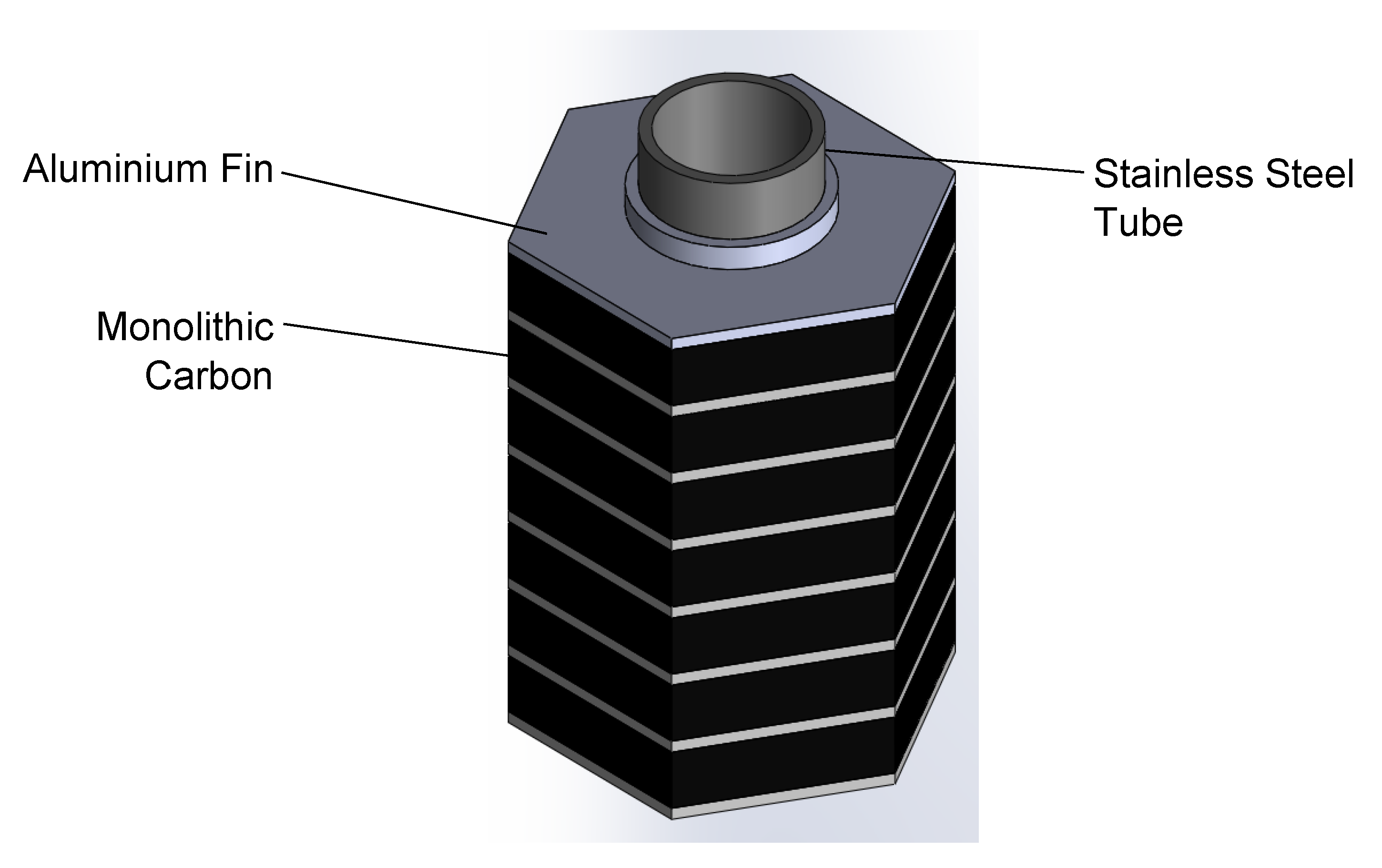
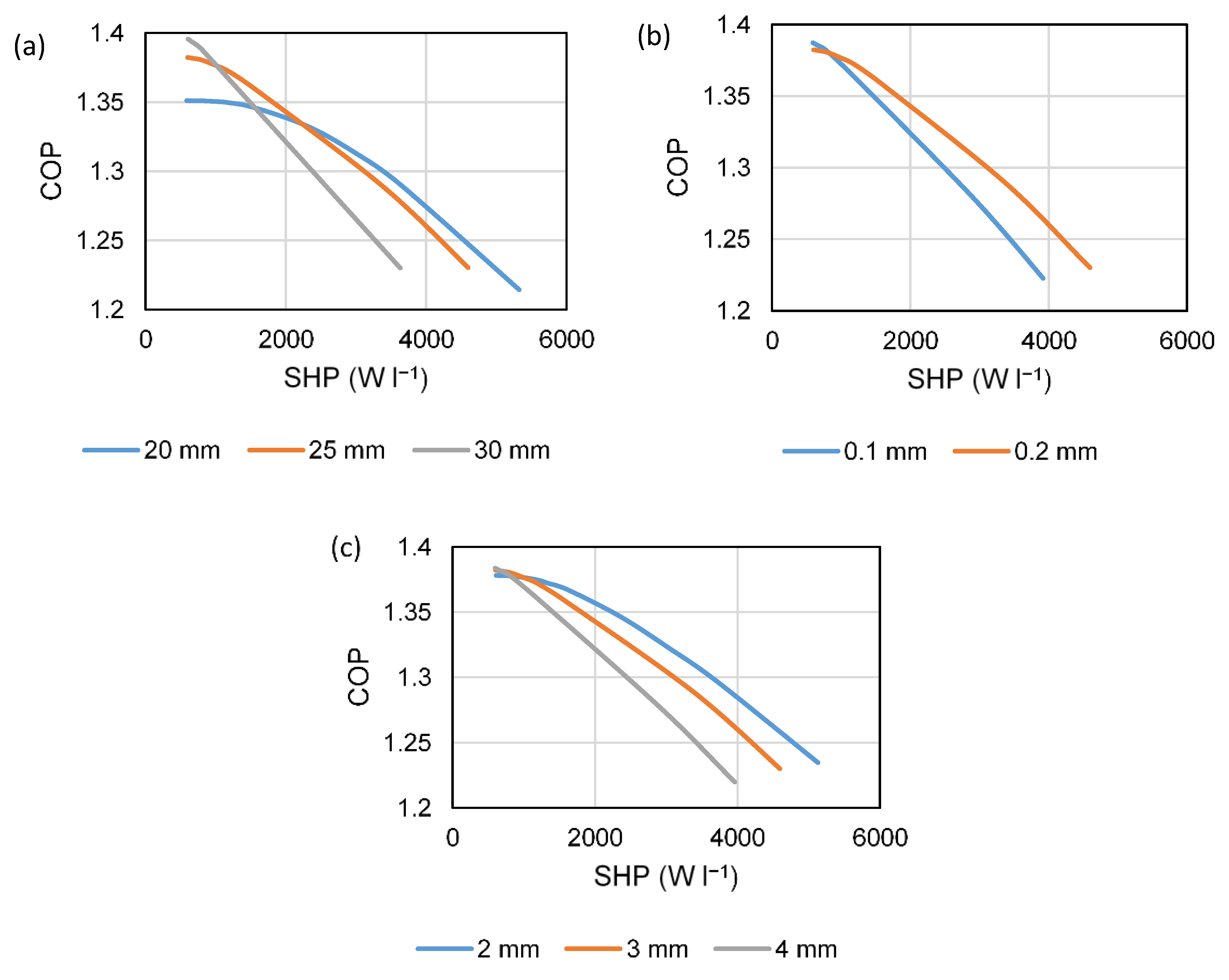
2.1. Preliminary Modelling and Design Parameters
Development of a computational model and preliminary investigation of dimensions was carried out in [33]. That work determined that as the tube diameter is made smaller the achievable power density and COP increases, but at the expense of an increase in the number of tubes required. The work analyzed 6-mm and 12-mm diameter tubes and found that for the same performance, up to 4 times more 6-mm tubes would be required than 12-mm ones (unless their length were made considerably longer). One of the major limiting factors for larger tubes was found to be the water-side heat transfer. This, however, could be enhanced using turbulence generating tube inserts, which could bring a 12-mm tube closer in performance to 6-mm tube (such inserts are not commonly available for tubes as small as 6 mm). The smallest commercially available tube inserts are suitable for a 10 mm/3/8” outer diameter tube, with an inner diameter in the region of 7 mm. This influenced the final decision to base the design around 3/8” tube.
Figure 3 shows the effect on performance of—(a) tube pitch/hexagon across-the-flats dimension (20, 25, and 30 mm), (b) aluminum fin thickness (0.1 and 0.2 mm), and (c) carbon layer thickness between the fins (2, 3, and 4 mm). The baseline values in each case are the final selected values given in Table 1. The modelled conditions were high-temperature heat input at 200 °C, a condensing temperature of 50 °C, and an evaporating temperature of 5 °C. Pressurized (liquid) water is the heat transfer fluid, which gives a higher heat transfer coefficient than the heat transfer oils. The round, stainless-steel tube design allows the generator to withstand the pressure level required (~16 bar), without excessive thermal mass.
Figure 3.
COP–SHP trade-off with a variation of parameters, (a) tube pitch, (b) aluminum fin thickness, and (c) carbon layer thickness.
Table 1.
Chosen geometry for module (and baseline values for comparisons).
A larger tube pitch gives a higher COP at low power due to the improved thermal mass ratio of heat exchanger to carbon, but it gives a reduced COP at a high power, due to the longer conduction path in the aluminum fin and the reduction in water-side heat transfer area per unit mass of carbon. A 25-mm pitch was chosen to give a good trade-off between high COP at a low power output, whilst still maintaining reasonable efficiency when operating at a higher output. The fin thickness selection was more obvious—the lower fin efficiency of the 0.1-mm fin results in a lower COP at all but the lowest expected output range (as the fins only account for a small amount of the overall thermal mass). It was also felt that 0.2 mm was the thinnest fin that could be used in practice, without tearing during the carbon compaction process. A 3-mm carbon layer thickness was selected, again as a trade-off between high efficiency at low power without experiencing too significant of a drop-off at high output. It can be seen that, in fact, perhaps 2 mm could enable a high-efficiency operation at a very high output power-density, but it was felt that this did not outweigh the requirement for additional layers to be pressed, which would add to the manufacturing cost.
The hexagonal modules must be hexagonally close packed within a cylindrical pressure vessel with minimal void volume, which means that there are a limited number of possible tube arrangements. The most efficient number of tubes to form such a close packed arrangement are given by the ‘centered hexagonal numbers’, which form the sequence 1, 7, 19, 37, 61, etc. With the chosen pitch of 25 mm, an arrangement of 19 tubes could be contained within a ~140 mm inner diameter shell. If the module length were 400 mm, then this would give a total module volume (2 generators) of 8.23 L and a total shell volume of 12.3 L. The necessary SHP for a nominal 10 kW machine would be 1.22 kW per liter. From Figure 1 it can be seen that the COP would then be 1.37. The final system would of course be driven by heat from a gas burner. The GUE could be calculated as:
If it is assumed that the burner operates with an efficiency, ηburner, of 0.8 (based on higher calorific value of gas) and that a further 10% of the gas input can be recovered directly to the load from the flue gases (i.e., ηfluerecov = 0.1), then the gas utilization efficiency would be 0.8 × 1.37 + 0.1 ≅ 1.2. If a compact and low cost system could be developed with a GUE of 1.2, then this could represent a sufficient increase in efficiency as compared to a condensing boiler (typical GUE 0.9), to warrant further development.
The final design could be refined with a more detailed model of the heat pump annual operation, but this is an extremely complex task, which depends on the climate, the building heat loss and heat emitters, and the chosen nominal power output of the system. This would also require coupling to manufacturing cost estimates, which are notoriously difficult to determine (particularly during early development stages). The driving temperature of 200 °C may add costs to components like pumps, valves, and expansion vessels, as the system would have to be pressurized to >15.5 bar to remain in the liquid phase. A compromise would be to operate at 175 °C/9 bar, where more standard and lower cost components could be used. The penalty in doing so is a reduction in the maximum COP from 1.378 to 1.371—a small reduction which is likely to be outweighed by the reduction in component costs.
2.2. Active Carbon Adsorbent
The monolithic carbon used was developed in [30,31]. The precursor material is a coconut-shell-derived, steam-activated granular material designated as ‘208C’, which has uptake characteristics well-suited to high driving temperature systems. The material is mixed with a commercial lignosulfonate binder and pressed to 150 MPa, to achieve a density of up to 840 kg m−3 and a conductivity of up to 0.5 W m−1 K−1. However, in this application, the required compaction pressure caused crushing of the tube, as shown in Figure 4.
Figure 4.
Preliminary trials with cylindrical modules caused crushing of the central tube.
The tube wall was already made as thick as is desirable, in order to maintain sufficient heat transfer area on the inside of the tube. The use of a central mandrel was considered, but this would become trapped due to the compression of the tube during the carbon compaction process and would require a difficult and time consuming operation to machine it out. The compaction pressure of the carbon was therefore reduced to 42.5 MPa, the limit to avoid crushing of the tube. The drawback of this was that it significantly reduced the density, conductivity, and strength of the monolithic carbon, so measures were needed to improve it. During the compaction with 155 MPa, the carbon grains are fractured and are forced to ‘fit together’ with less void space, giving a high density and conductivity. The solution to achieve a similar density with a lower compaction pressure was to use a mixture of carbon grains and carbon powder. The carbon powder fills in the voids between the grains, creating a higher density and conductivity than with grains alone. The optimal mix was found to be one-third by mass powder and two-thirds by mass grains. The properties of the resulting monolithic carbon are given in Table 2.
Table 2.
Monolithic carbon properties.
The uptake of ammonia can be calculated by a modified form of the Dubinin–Astakhov (D–A) equation [34], with the parameters given in Table 2:
where T is the adsorbent temperature, Tsat is the saturation temperature, x0 is the limiting mass concentration of ammonia, and K and n are constants for the adsorbent–adsorbate pair.
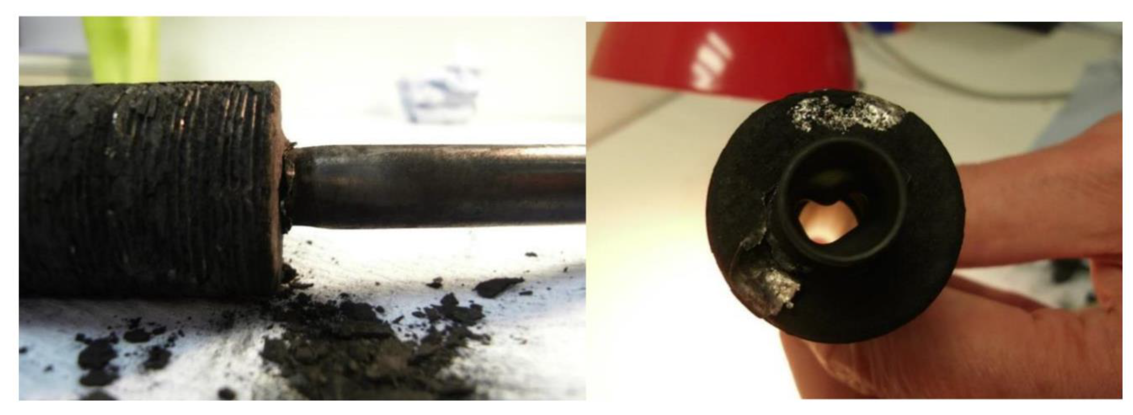
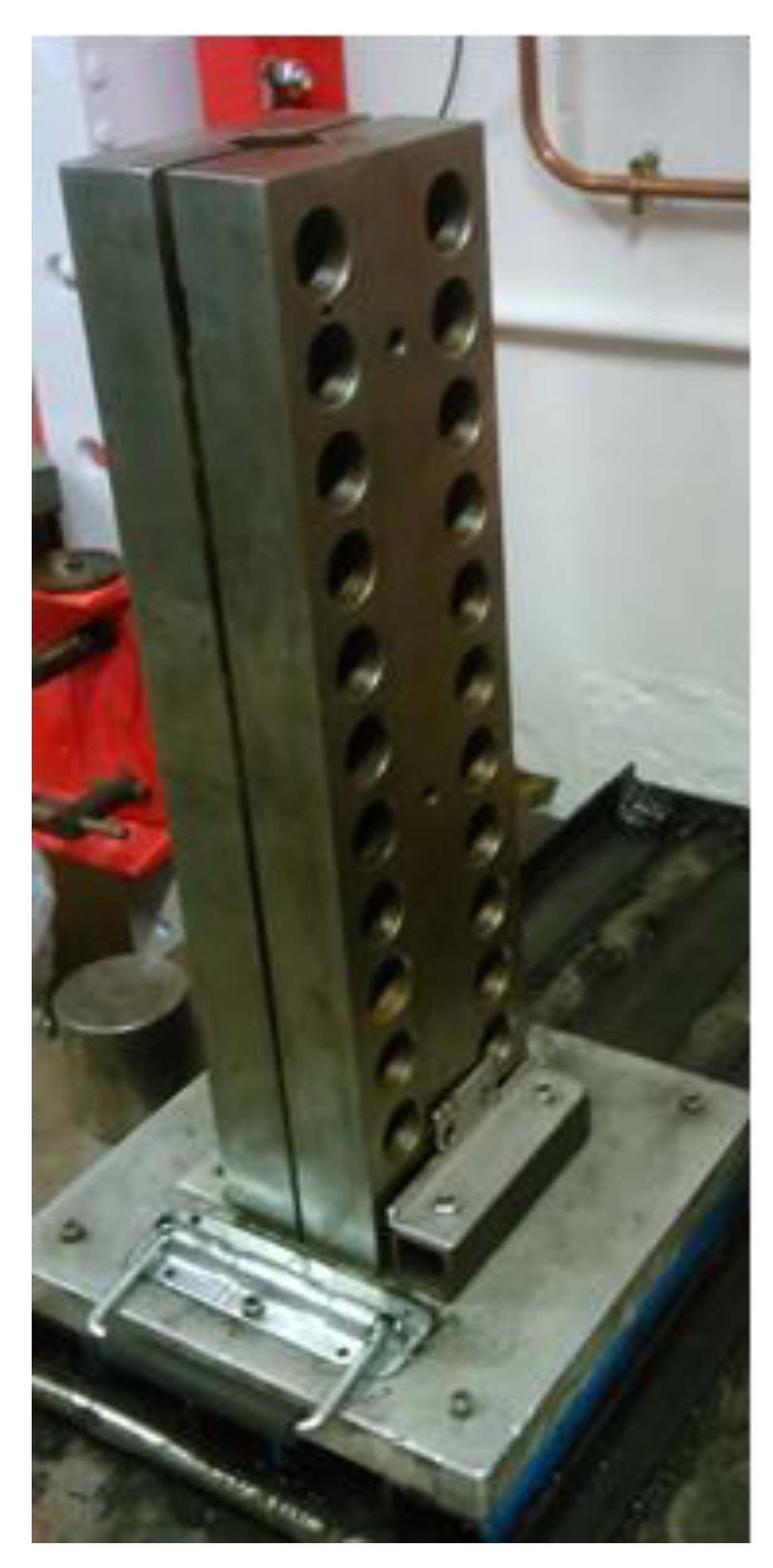
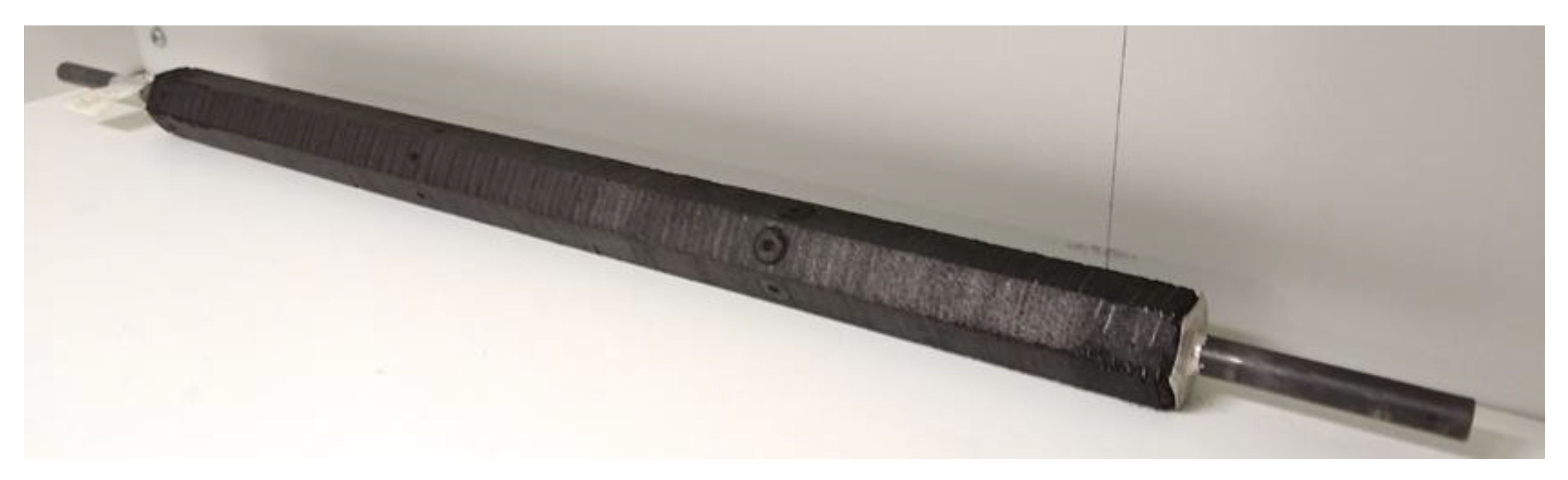
2.3. Module Manufacture
The aluminum fins are stamped from 0.2-mm thick aluminum sheet, using a purpose-made hexagonal steel punch and die, which cuts a central 7-mm hole at the same time as producing the hexagonal outer profile. The fin collar is then produced using the swaging tool shown in Figure 5, which expands the central hole to 9.5 mm/3/8” and folds the material into a ~1-mm high collar.
Figure 5.
Fin collar forming swaging tool (left) and the resulting fin (right).
The 3/8” stainless steel tube is then placed inside the hexagonal split mold shown in Figure 6, and the first aluminum fin is slid down the tube using a steel plunger. The carbon and binder mixture is then poured into the mold on top of the fin and pressed to 42.5 MPa (i.e., with a force of 20 kN), using a steel plunger in a hydraulic press. The pressing operation not only compacts the carbon and enables the binder to consolidate it, but it also creates thermal contact between the carbon and the fin, and presses the fin against the tube to create good fin–tube thermal contact. This process is continued until 125 layers have been built up to create a total fin-carbon laminate length of 400 mm. However, initial trials were carried out on 100-mm, 200-mm, and 300-mm long modules before scaling up to the full size. A completed 400-mm long module is shown in Figure 7.
Figure 6.
Hexagonal split mold.
Figure 7.
Completed aluminum–carbon laminate tube module.
Investigations were carried out into pressing multiple layers at a time in order to speed up the manufacturing process, but it was discovered that this caused damage to the fins and allowed carbon to be squeezed between the fin collar and the tube. The compression distance when pressing multiple layers was significant, as the carbon compacted from its loose, uncompressed density of ~500 kg m−3. The layers were, therefore, compressed one-by-one. It was envisaged that during mass production, multiple molds would be positioned on a carousel and would automatically rotate between a linear motor station for sliding down fins, a hopper station for loading carbon, and a pressing station for the compression process.
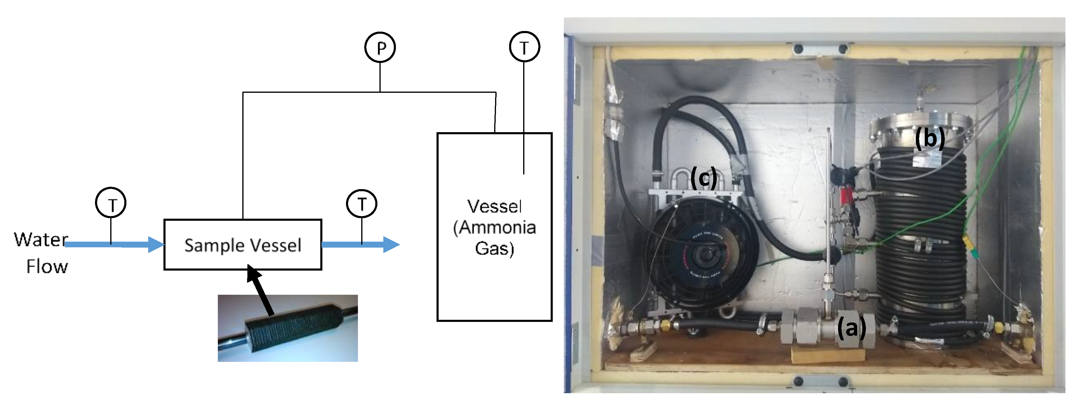
2.4. Large Temperature Jump Apparatus
The large temperature jump (LTJ) apparatus is shown in Figure 8. The object of the experiment was to subject the module under test to the same jump in temperature that would be experienced during a real cycle at an almost constant pressure. The pressure was controlled by charging a large gas receiver vessel with ammonia at a measured temperature and pressure. The temperature of the vessel and enclosure was controlled by a thermostatic bath, which circulated water through tubes wrapped around the vessel and a fan coil inside the enclosure. The temperature was set at a level high enough to prevent condensation in the vessel or in the interconnecting pipework. The volume of the vessel (in this case 6.692 ± 0.01 L) was selected such that the change in pressure was relatively small during adsorption and desorption of the module, but large enough to be measured with sufficient accuracy to be able to calculate the mass adsorbed or desorbed. The measured pressure change during the temperature jump was used to determine the amount and rate of adsorption or desorption and thereby assess the performance of the module. A comparison was made between the result of the experiment and the computational model in order to determine if the module behaved as predicted.
Figure 8.
Large temperature jump apparatus. Schematic (left) and actual system (right). (a) Sample vessel, (b) receiver vessel wrapped with tubing, and (c) enclosure heater (fan coil). Key: P = pressure transducer, T = temperature sensor.
An idealized, typical heat pump cycle is shown on the Clapeyron diagram in Figure 9. Adsorption occurs at around 5–6 bar abs. (5–10 °C saturation temperature) and from 113 °C down to 50 °C. It is the adsorption conditions that are the most important to test, as the rate of adsorption is lower than desorption due to the lower gas density (higher gas velocity and pressure drop) and the smaller driving temperature difference available (isosteres are closer together at lower temperature). The heat transfer coefficient on the water side would also be lower during adsorption, due to the higher viscosity of water at lower temperatures, which reduces the amount of turbulence. Since adsorption begins at 113 °C, the water would require pressurization to prevent boiling if the test conditions were to completely match the real cycle. The LTJ apparatus uses open baths and in order to provide pressurized water they would have to be filled with a heat transfer oil and the heat transferred to a pressurized water circuit via a heat exchanger. In order to avoid this complication, the large temperature jump was instead made between 25 °C and 80 °C, and the open baths were used directly.
Figure 9.
Clapeyron diagram of the typical heat pump cycle.
Table 3 shows that these conditions result in a similar concentration change in the carbon, as calculated by the modified D-A Equation (3). Since the adsorption reaction was a physical rather than a chemical one, the rate was not strongly affected by the absolute temperature. The main objective of the test was to validate the model predictions and confirm if the heat transfer performance of the module was as expected.
Table 3.
Real cycle conditions vs. LTJ conditions for adsorption.
Pressure was measured using a 0–10 V pressure transmitter, calibrated with a deadweight tester to a combined accuracy and repeatability of ±0.02 bar. The inlet and outlet temperatures of the water and the internal temperature in the gas vessel were measured with K-type, 1-mm diameter, stainless-steel-sheathed thermocouples, with an accuracy of ±0.2 °C. The combined error in the pressure, temperature, and vessel volume measurement gave an error in the calculated adsorption or desorption from the experiment of ±0.13 g. The 300-mm long module tested had a total carbon mass of 105 g and adsorbed and desorbed 13.125 g, giving an error margin on the calculated mass of ammonia adsorbed and desorbed of ±1%. Readings were made with a data logger connected to a laptop computer and set to a sampling rate of 1 Hz, in order to give a sufficient temporal resolution to the data.
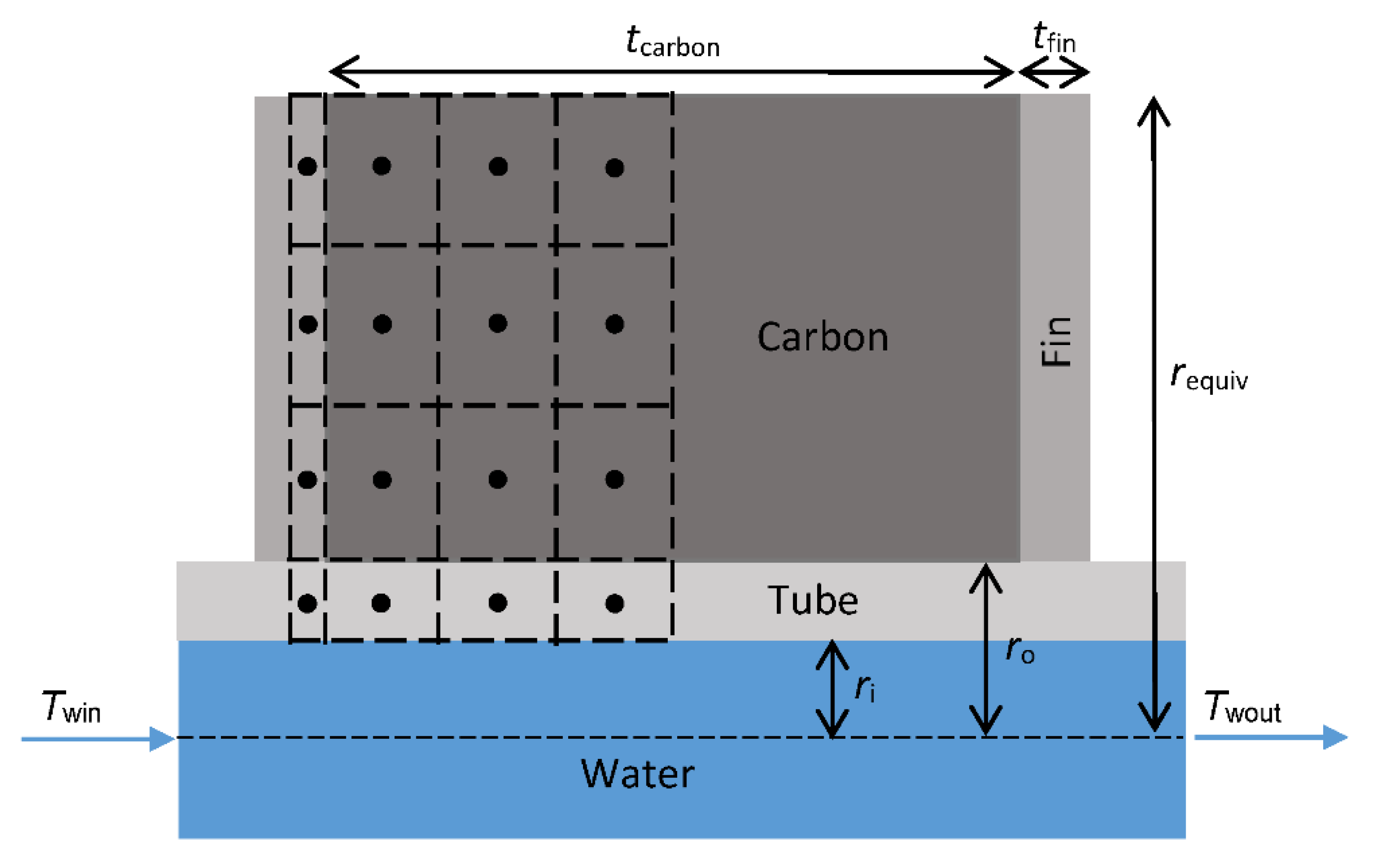
2.5. Large Temperature Jump Model
The computational model is presented in [33] but details are included here for completeness, particularly in respect to the way in which the model is used to analyze the LTJ results. The model is written in MATLAB (version R2020a, Natick, MA, USA) and is a finite difference model with a forward Euler time scheme. The geometry is discretized radially, as shown in Figure 10, and takes advantage of symmetry to model only half of one fin and carbon layer.
Figure 10.
Discretization of the control volume in the finite difference model.
The model approximates the hexagon as a cylinder of the same volume. The radius, requiv, of the equivalent cylinder is therefore calculated as:
where rAF is the radius across the flats of the hexagon. The carbon can be divided into nl cells axially and nr cells radially, where nl and nr are any positive integer. However, for speed and accuracy, it was determined that a 3 × 3 grid in the carbon was optimal (as illustrated in Figure 10).
The ammonia uptake is calculated from Equation (3) and the material property values assumed in the model are given in Table 4. The heat of adsorption, Hads, is calculated as:
where C is the slope of the ammonia saturation line on a Clapeyron diagram (value taken to be 2823.4), p is the ammonia pressure, and νg is the specific volume of ammonia gas (calculated from a high-order polynomial fit to data from tables).
Table 4.
Property values used in the computational model.
The mass of ammonia gas in the vessel is calculated as:
and the gas-specific volume is again calculated with a high-order polynomial data fit. Similarly, the mass of ammonia gas in the sample cell is calculated as follows:
The gas in the sample cell is assumed to be at the carbon temperature, Tc. This approximation is acceptable as the sample vessel void volume, Vsamplecell, is only 0.2 L, and is therefore only 3% of that of the large receiver vessel.
The water-side heat transfer coefficient was obtained from the tube insert manufacturer’s calculation software for the given conditions and is also given in Table 4. The flow rate of water during testing is relatively high and the temperature drops low, and therefore, the model uses a simple average of the inlet and outlet water temperature to calculate the heat transfer from the water to the tube wall per cell:
The remaining heat transfer is by conduction.
The inputs to the model from the experiment were the water inlet and outlet temperatures and vessel temperature throughout the duration of the test and the initial ammonia pressure. The model then calculated the pressure change due to the change in the water temperature and the result was compared to the model.
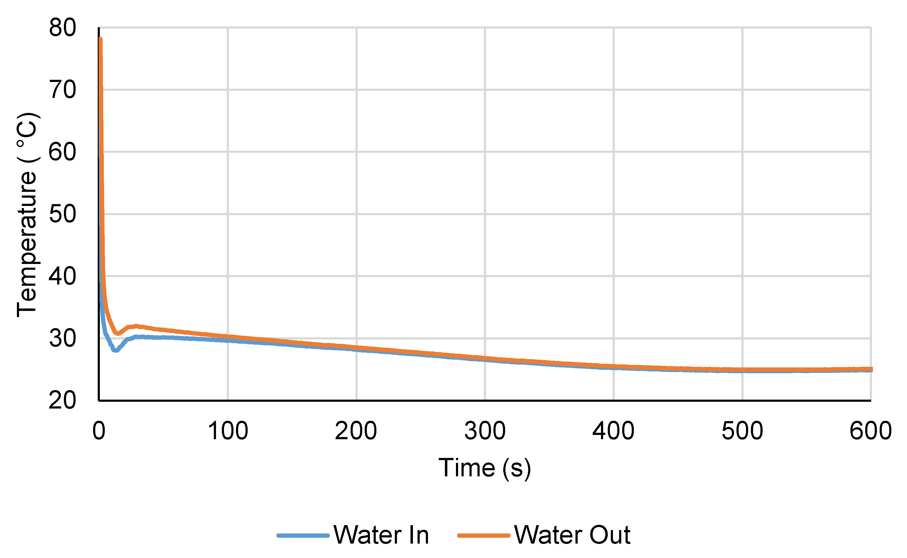
3. Results and Discussion
The inlet and outlet water temperatures during the LTJ adsorption test are shown in Figure 11. It can be seen that the temperature jump was not quite ideal and the bath took a while after the initial transient to reach the set temperature of 25 °C. However, the inlet temperature was below 35 °C after the first 2.5 s and after 5 s, it was 30 °C or lower for the remainder of the test. In comparing the performance of the module to the simulation model, the water inlet temperature measured during the experiment was used as an input to the model in order to account for this. Figure 12 plots the pressure change during the LTJ adsorption test, together with the predictions from the simulation model for a carbon thermal conductivity of 0.2, 0.3, and 0.4 W m−1 K−1. This could be considered to be an effective carbon thermal conductivity—the model assumed perfect tube-fin contact and carbon-fin contact and it was not possible to differentiate between the effects of contact resistance and the bulk conductivity of the carbon from the tests. The complete effect of contact resistance, bulk thermal conductivity, and for that matter any mass transfer resistance, was accounted for by this effective thermal conductivity value. The key part of the test was in the first 200 s or so—after this period, the changes were mainly due to the bath reaching its set temperature and the carbon slowly cooling to 25 °C (hence, the lines for different thermal conductivities converged after 200 s).
Figure 11.
Inlet and outlet water temperature during the LTJ adsorption test.
Figure 12.
Pressure change during the LTJ adsorption test and comparison to model with carbon conductivity of 0.2, 0.3, and 0.4 W m−1 K−1 (300-mm module).
It can be seen from Figure 12 that the effective thermal conductivity lay somewhere between 0.3 and 0.4 W m−1 K−1, which given the fact that the bulk conductivity of the carbon was measured to be 0.4 Wm−1 K−1 from the steady-state thermal conductivity measurements, indicated that the tube-fin and carbon-fin contact resistance was low.
Figure 13 shows the desorption test under the same conditions, and again the effective thermal conductivity lay somewhere between 0.3 and 0.4 W m−1 K−1. The time constant for the module (the time to complete 63.2% of the concentration change) was about 50 s.
Figure 13.
LTJ desorption test pressure change and comparison to model (300-mm module).
Running the model with a range of conductivity values between 0.3 and 0.4 W m−1 K−1, the lowest root mean squared error between the model and experiment was achieved with a conductivity of 0.36 ± 0.01 W m−1 K−1. The module therefore behaved as expected, with only a slight correction required to the effective thermal conductivity of the carbon from 0.4 to 0.36 W m−1 K−1. The effect of this on the cycling rate of the module was almost negligible (as can be seen from Figure 12 and Figure 13) and did not warrant correction of the model predictions in Figure 3 (<1% change to the COP and SHP when entered back into the cycle simulation model). It was not possible to deduce the cause of the lower effective carbon conductivity than that of the bulk from the test, but it was most likely due to the fin to tube contact. Upon deconstructing the modules for examination, each fin collar had a thin layer of carbon between it and the tube, which would cause some contact resistance.
The next step in the development and proof of the concept would be to scale up the modules into a full-sized generator. Since the volume of vessel required to test a full-size generator in an LTJ test would be large (127 L if directly scaled from the test system for a single module), it would perhaps be preferable to instead test the generator with a condenser and evaporator. If such a system were to be constructed, then it may be advantageous to construct two generators and operate them in a proper cycle, with heat and mass recovery between beds. The driving heat, however, would still be provided by an electric heater, in order to focus the development on the adsorption system. The COP and heating power predicted by the system model could then be validated.
4. Conclusions
The proposed modular finned tube adsorption generator design was constructed and its performance was verified by large temperature jump tests. The module performed as predicted and had a time constant of 50 s. It is predicted that a machine constructed with the modules could achieve a gas utilization efficiency of 1.2 and an output of 10 kW, with a total generator volume of only 12.3 L.
Author Contributions
Conceptualization, all; methodology, all; software/model generation, R.C., Á.R.-P.; manufacture and testing, S.M. and Á.R.-P.; validation, S.M. and Á.R.-P.; writing—original draft preparation, S.M.; writing—review and editing, all; project administration, R.C. All authors have read and agreed to the published version of the manuscript.
Funding
This research was funded by the UK EPSRC grants ‘i-STUTE’ EP/K011847/1 and ‘4S-DHW’ EP/N021304/1 and by the UK government department BEIS grant LCHTIF1021 ‘Gas Adsorption Heat Pump’.
Institutional Review Board Statement
Not applicable.
Informed Consent Statement
Not applicable.
Data Availability Statement
Additional model and experimental data are available at: wrap.warwick.ac.uk. Date accessed on 4 June 2021.
Conflicts of Interest
The authors declare no conflict of interest.
Nomenclature and Subscripts
| Symbol | Unit | Description |
| η | - | Efficiency |
| ν | m3 kg−1 | Specific volume |
| C | - | Slope of ammonia saturation line on a Clapeyron diagram |
| Hads | J kg−1 | Heat of adsorption |
| h | W m−2 K−1 | Heat transfer coefficient |
| k | W m−1 K−1 | Thermal conductivity |
| l | m | Length (axial direction) |
| K | - | D-A equation coefficient |
| n | - | D-A equation exponent |
| p | Pa | Pressure |
| Q | J | Heat |
| W | Rate of heat flow | |
| T | K | Temperature |
| V | m3 | Volume |
| x | kg kg−1 | Adsorbate concentration |
| Subscripts | Description | |
| 0 | Limiting value | |
| ads | Adsorption | |
| AF | Across flats | |
| cell | Finite difference cell | |
| cond | Condenser | |
| fluerecov | Flue gas heat recovery | |
| HTin | High temperature input | |
| sat | Saturation | |
| w | Water | |
| wall | Tube wall | |
| win | Water inlet | |
| wout | Water outlet | |
References
- Ürge-Vorsatz, D.; Cabeza, L.F.; Serrano, S.; Barr, C. Heating and cooling energy trends and drivers in buildings. Renew. Sustain. Energy Rev. 2015, 41, 85–98. [Google Scholar] [CrossRef]
- Intergovernmental Panel on Climate Change. Climate Change 2014 Mitigation of Climate Change Working Group III Contribution to the Fifth Assessment Report of the Intergovernmental Panel on Climate Change; Cambridge University Press: Cambridge, UK, 2014; ISBN 978-1-107-65481-5. [Google Scholar]
- Delta-EE. IEA HPT Programme Annex 42: Heat Pumps in Smart Grids Task 4: Roadmap, IEA Heat Pump Centre; Report No. HPT-AN42-1; Sweden, 2018; ISBN 978-91-88695-05-5. [Google Scholar]
- Lapsa, M.V.; Khowailed, G.; Sikes, K.; Baxter, V. Heat Pumps in North America—2017 Regional Report. In Proceedings of the 12th IEA Heat Pump Conference, Rotterdam, The Netherlands, 1–30 June 2017; ISBN 978-90-9030412-0. [Google Scholar]
- Baxter, V.; Sikes, K.; Domitrovic, R. IEA HPP Annex 42 Heat Pumps in Smart Grids—Task 1 Market Overview United States; ORNL/TM-2014/73; 2014. Available online: https://info.ornl.gov/sites/publications/files/Pub48773.pdf (accessed on 4 June 2021).
- BSRIA. World Heating: Domestic & Commercial Boilers 2020; 2020; Available online: https://www.bsria.com/uk/market-intelligence/market_reports/heating/ (accessed on 4 June 2021).
- Heat Pump Centre. Annex 43 Fuel Driven Sorption Heat Pumps Final Report; Report No. HPT-AN43-1; Sweden, 2020; ISBN 978-91-89167-50-6. [Google Scholar]
- Wittstadt, U.; Füldner, G.; Vasta, S.; Volmer, R.; Bendix, P.; Schnabel, L.; Mittelbach, W. Adsorption Heat Pumps and Chillers—Recent Developments for Materials and Components. In Proceedings of the 12th IEA Heat Pump Conference, Rotterdam, The Netherlands, 1–30 June 2017; ISBN 978-90-9030412-0. [Google Scholar]
- Füldner, G. ADOSO—Gas Adsorption Heat Pump with a Crystalline Zeolite Heat Exchanger and a Novel Evaporator-condenser Device, German Federal Ministry of Economic Affairs and Energy (BMWi) Project; 2017; Available online: https://www.ise.fraunhofer.de/en/research-projects/adoso.html (accessed on 4 June 2021).
- Aprile, M.; Scoccia, R.; Toppi, T.; Guerra, M.; Motta, M. Modelling and experimental analysis of a GAX NH3-H2O gas-driven absorption heat pump. Int. J. Refrig. 2016, 66, 145–155. [Google Scholar] [CrossRef]
- Garrabrant, M.; Stout, R.; Blaylock, M.; Keinath, C. Residential and Commercial Capacity Absorption Heat Pumps for Space and Domestic Water Heating Applications. In Proceedings of the 12th IEA Heat Pump Conference, Rotterdam, The Netherlands, 1–30 June 2017; ISBN 978-90-9030412-0. [Google Scholar]
- Blackman, C.; Bales, C.; Thorin, E. Experimental Evaluation and Concept Demonstration of a Novel Modular Gas-Driven Sorption Heat Pump. In Proceedings of the 12th IEA Heat Pump Conference, Rotterdam, The Netherlands, 1–30 June 2017; ISBN 978-90-9030412-0. [Google Scholar]
- Gluesenkamp, K.R.; Frazzica, A.; Velte, A.; Metcalf, S.J.; Yang, Z.; Rouhani, M.; Blackman, C.; Qu, M.; Laurenz, E.; Rivero-Pacho, A.; et al. Experimentally measured thermal masses of adsorption heat exchangers. Energies 2020, 13, 1150. [Google Scholar] [CrossRef]
- Wang, R.; Xia, Z.; Wang, L.; Lu, Z.; Li, S.; Li, T.; Wu, J.; He, S. Heat transfer design in adsorption refrigeration systems for efficient use of low-grade thermal energy. Energy 2011, 36, 5425–5439. [Google Scholar] [CrossRef]
- Tamainot-Telto, Z.; Metcalf, S.; Critoph, R. Novel compact sorption generators for car air conditioning. Int. J. Refrig. 2009, 32, 727–733. [Google Scholar] [CrossRef][Green Version]
- Mikhaeil, M.; Gaderer, M.; Dawoud, B. On the development of an innovative adsorber plate heat exchanger for adsorption heat transformation processes; an experimental and numerical study. Energy 2020, 207, 118272. [Google Scholar] [CrossRef]
- Sapienza, A.; Brancato, V.; Aristov, Y.; Vasta, S. Plastic heat exchangers for adsorption cooling: Thermodynamic and dynamic performance. Appl. Therm. Eng. 2021, 188, 116622. [Google Scholar] [CrossRef]
- Sapienza, A.; Santamaria, S.; Frazzica, A.; Freni, A. Influence of the management strategy and operating conditions on the performance of an adsorption chiller. Energy 2011, 36, 5532–5538. [Google Scholar] [CrossRef]
- Frazzicaa, A.; Palombaa, V.; Dawoud, B.; Gullì, G.; Brancato, V.; Sapienza, A.; Vasta, S.; Freni, A.; Costa, F.; Restuccia, G. Design, realization and testing of an adsorption refrigerator based on activated carbon/ethanol working pair. Appl. Energy 2016, 174, 15–24. [Google Scholar] [CrossRef]
- Freni, A.; Bonaccorsi, L.; Calabrese, L.; Caprì, A.; Frazzica, A.; Sapienzaa, A. SAPO-34 coated adsorbent heat exchanger for adsorption chillers. Appl. Therm. Eng. 2015, 82, 1–7. [Google Scholar] [CrossRef]
- Bendix, P.; Füldner, G.; Möllers, M.; Kummer, H.; Schnabel, L.; Henninger, S.; Henning, H.-M. Optimization of power density and metal-to-adsorbent weight ratio in coated adsorbers for adsorptive heat transformation applications. Appl. Therm. Eng. 2017, 124, 83–90. [Google Scholar] [CrossRef]
- Li, S.; Xia, Z.; Wu, J.; Li, J.; Wang, R.; Wang, L. Experimental study of a novel CaCl2/expanded graphite-NH3 adsorption refrigerator. Int. J. Refrig. 2010, 33, 61–69. [Google Scholar] [CrossRef]
- Sharafian, A.; Mahdi, S.; Mehr, N.; Thimmaiah, P.; Huttema, W.; Bahrami, M. Effects of adsorbent mass and number of adsorber beds on the performance of a waste heat-driven adsorption cooling system for vehicle air conditioning applications. Energy 2016, 112, 481–493. [Google Scholar] [CrossRef]
- Jiang, L.; Wang, L.; Liu, C.; Wang, R. Experimental study on a resorption system for power and refrigeration cogeneration. Energy 2016, 97, 182–190. [Google Scholar] [CrossRef]
- Rocky, K.A.; Pal, A.; Rupam, T.H.; Palash, M.L.; Saha, B.B. Recent advances of composite adsorbents for heat transformation applications. Therm. Sci. Eng. Prog. 2021, 23, 100900. [Google Scholar] [CrossRef]
- Wang, K.; Wu, J.; Wang, R.; Wang, L. Composite adsorbent of CaCl2 and expanded graphite for adsorption ice maker on fishing boats. Int. J. Refrig. 2006, 29, 199–210. [Google Scholar] [CrossRef]
- Wang, W.L.; Tamainot-Telto, Z.; Thorpe, R.; Critoph, R.E.; Metcalf, S.J.; Wang, R.Z. Study of thermal conductivity, permeability, and adsorption performance of consolidated composite activated carbon adsorbent for refrigeration. Renew. Energy 2011, 36, 2062–2066. [Google Scholar] [CrossRef]
- Wittstadt, U.; Füldner, G.; Andersen, O.; Herrmann, R.; Schmidt, F. A New Adsorbent Composite Material Based on Metal Fiber Technology and Its Application in Adsorption Heat Exchangers. Energies 2015, 8, 8431–8446. [Google Scholar] [CrossRef]
- Velte, A.; Weise, J.; Laurenz, E.; Baumeister, J.; Füldner, G. Zeolite NaY-Copper Composites Produced by Sintering Processes for Adsorption Heat Transformation—Technology, Structure and Performance. Energies 2021, 14, 1958. [Google Scholar] [CrossRef]
- Tamainot-Telto, Z.; Critoph, R.E. Monolithic carbon for sorption refrigeration and heat. Appl. Therm. Eng. 2001, 21, 37–52. [Google Scholar] [CrossRef]
- Tamainot-Telto, Z.; Critoph, R.E. Thermophysical properties of monolithic carbon. Int. J. Heat Mass Transf. 2000, 43, 2053–2058. [Google Scholar] [CrossRef]
- Aristov, Y.; Dawoud, B.; Glazneva, I.; Elyasc, A. A new methodology of studying the dynamics of water sorption/desorption under real operating conditions of adsorption heat pumps: Experiment. Int. J. Heat Mass Transf. 2008, 51, 4966–4972. [Google Scholar] [CrossRef]
- Rivero-Pacho, A.M.; Critoph, R.E.; Metcalf, S.J. Modelling and development of a generator for a domestic gas-fired. Renew. Energy 2017, 110, 180–185. [Google Scholar] [CrossRef]
- Critoph, R.E. Adsorption Refrigerators and Heat Pumps, in Carbon Materials for Advanced Technologies; Elsevier: Amsterdam, The Netherlands, 1999. [Google Scholar]
- Turner, L. Improvement of Activated Charcoal-Ammonia Adsorption Heat Pumping/Refrigeration Cycles. Investigation of Porosity and Heat/Mass Transfer Characteristics. Ph.D. Thesis, University of Warwick, Coventry, UK, June 1992. Available online: http://wrap.warwick.ac.uk/35984 (accessed on 4 June 2021).
Publisher’s Note: MDPI stays neutral with regard to jurisdictional claims in published maps and institutional affiliations. |
© 2021 by the authors. Licensee MDPI, Basel, Switzerland. This article is an open access article distributed under the terms and conditions of the Creative Commons Attribution (CC BY) license (https://creativecommons.org/licenses/by/4.0/).