Abstract
The application of a catalyst on a surface inside a combustion chamber is known as a supplementary method of exhaust gas aftertreatment. The efficiency of this method in the reduction in exhaust emissions as well as its influence on other engine properties has been analyzed in multiple scientific works. Most often, these works present the results of investigations carried out on dynamometers under engine stationary conditions. There are no results of the catalyst investigations performed under dynamic states, particularly on-going real time analyses during engine operation. Therefore, the authors set out to explore the efficiency of the in-cylinder catalyst of a diesel engine under dynamic conditions simulating actual vehicle operation. A unique methodology was applied. The investigations were carried out in road conditions in a test simulating the New European Driving Cycle (NEDC) homologation test in compliance with the similarity criteria of the zero-dimensional characteristics of vehicle speed during the investigations and in the homologation test. For the research, the authors used portable exhaust emissions measurement equipment. A unique method of test results analysis was also applied (a continuous method in the time domain). As a result of the tests being repeated several times, it was observed that the application of an internal catalyst under different operating engine conditions repeatedly results in: an approx. 2% reduction in the emissions of carbon monoxide, hydrocarbons, and carbon dioxide; a similar increase in the emission of nitrogen oxides; and a significant (over 10%) reduction in the particle number. The obtained results substantiate the purpose of actions aiming at improving the efficiency of the internal catalyst.
1. Introduction
Environmental protection to mitigate the effects of civilization also applies to a large extent to the automotive industry and the use of internal combustion engines in general. The main environmental threats from the operation of internal combustion engines are the emissions of pollutants harmful to the health of living organisms as well as other substances harmful to the environment, primarily gases contributing to the intensification of the greenhouse effect [,]. The requirements set out for the properties of internal combustion engines due to environmental protection have led to the search for increasingly advanced technical solutions. These activities mainly include phenomena such as fuel dosage, air-fuel mixture formation, combustion, exhaust gas aftertreatment, and, above all, the control of the combustion processes occurring in the engine [,]. The development of catalytic exhaust aftertreatment methods has been particularly beneficial. The possibilities of affecting the fuel combustion processes in the engine cylinder are relatively small. This is due in part to the physical limitations. In this paper, the problem of the impact of the catalyst coating on the combustion process in the engine cylinder is investigated.
Efforts towards the use of catalysts in the combustion chamber have been made, and the results obtained are encouraging. Various methods of introducing catalysts into the combustion chamber are used, including coating catalyst layers on various components of the combustion chamber, such as the piston crown, or by using catalytic inserts in the combustion chamber [,,,,]. Ref. [] constitutes a patent for the production of a glow plug. The positive results of the application of this solution in terms of exhaust emissions were described in []. In [], the following were considered as a ceramic coating: zirconium dioxide stabilized with yttrium monoxide, and lanthanum zirconate and oxides of the rare earth metals. In [], the authors analyzed the influence of the application of the thermal barrier coatings (nanoceramic insulation applied on the surface of the combustion chamber, piston crowns, and cylinders) on the overall engine efficiency. In [], the authors described the possibility of reduction in the temperature of autoignition of the injected fuel following the application of a rhodium catalytic coating inside the combustion chamber. Additionally, various substances and different methods of applying catalyst layers in the combustion chamber and individual components of the internal combustion engine were tested. The results of extensive research in this field were discussed in [,].
The existing publications mainly pertain to empirical research under stationary conditions. There are no investigations under dynamic conditions (indexes averaged in time and on-going analyses). This is particularly important for engines applied in vehicles. The states of operation of vehicle engines are characterized by a high variability of engine speeds and loads. Moreover, there are no publications on the influence of the internal catalysts on the engine properties under actual operating conditions. To that end, the authors proposed investigations with the use of a portable exhaust emissions measurement system, simulating the actual vehicle operation in city traffic. The exhaust emissions tests were carried out on an on-going basis, which allowed a real time assessment of the efficiency of the applied internal catalyst solution under the dynamic conditions of operation.
The solution of placing a platinum-coated glow plug is unique and original on a global scale. The technology of application of the platinum coat is also unique. The results of investigations performed by the authors to date substantiate the purpose of development of this concept in terms of the reduction in exhaust emissions from diesel engines.
2. The Aim, Plan, and Test Object
The aim of the study was to assess the internal catalyst efficiency in a compression-ignition engine in dynamic engine operating conditions. The engine operating conditions were determined by the conditions of passenger car operated in road traffic. The test object was a Fiat 1.3 JTD (MultiJet) engine (Fiat Chrysler Automobiles, Amsterdam, Netherlands). The engine technical data are presented in Table 1. The latest generation engine was deliberately selected for testing in order to expose the sensitivity of the exhaust emissions level to the use of an internal catalyst. The Fiat 1.3 JTD engine is fitted in the Fiat Idea car model.

Table 1.
Technical specifications of the 1.3 JTD (MultiJet) combustion engine.
The research program included performing a representation of the Malta test on the engine dynamometer. The Malta test [,] was developed at the Poznan University of Technology to simulate the New European Driving Cycle (NEDC) type approval test in road conditions []. The NEDC cycle was developed based on the synthesis of the vehicle acceleration in accordance with the assumed characteristics of the vehicle driving cycle [], e.g., average vehicle speed, maximum vehicle speed, extreme acceleration values, vehicle probability density, etc., as determined in the empirical studies of vehicle operation under real driving conditions.
This method of developing a road test makes the traffic conditions usually less dynamic than they would be in the case of actual road traffic. Therefore, there is a common tendency to create driving tests in accordance with the principle of faithful simulation of the vehicle in the time domain based on the recorded mileage of cars in their actual operating conditions []. The Malta test is one of such tests (Figure 1).
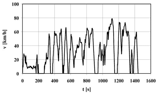
Figure 1.
Vehicle velocity (v) in the Malta test as a function of time (t).
Relative torque is defined as:
where n is the engine speed, Me is the torque, and Me ext is the torque at the maximum engine control setting.
This test is characterized by the values of zero-dimensional characteristics of the velocity similar to the values of these characteristics in the NEDC test (New European Driving Cycle). Performing the Malta test with a Fiat Idea (Fiat Chrysler Automobiles, Amsterdam, Netherlands) determines the engine operating states shown in Figure 2 and Figure 3.
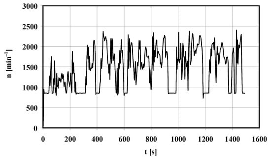
Figure 2.
Engine speed (n) in the Malta test as a function of time (t).
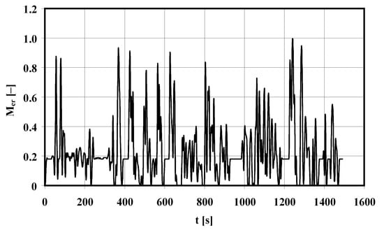
Figure 3.
Relative engine torque (Mer) in the Malta test as a function of time (t).
The engine dynamometer test, performed in accordance with the engine speed and torque as reflected in the Malta test, was carried out on the engine in a thermally stable condition. An AVL Dynoroad 120 kW test stand adapted for testing in dynamic conditions was used for the tests on the engine dynamometer. The exhaust gas analysis was performed using a Semtech DS analyzer (Sensors, Inc., MI, USA), equipped with the following measuring modules:
- FID—Flame Ionization Detector for determining the concentration of hydrocarbons,
- NDUV (Non-Dispersive Ultraviolet)—a non-dispersive analyzer using ultraviolet radiation to measure the concentration of nitrogen monoxide and dioxide,
- NIDR (Non-Dispersive Infrared)—a non-dispersive analyzer using infrared radiation to measure the concentration of carbon monoxide and dioxide,
- an electrochemical analyzer for determining the concentration of oxygen.
The exhaust mass flow rate was also measured using the Semtech DS analyzer. The TSI 3090 EPSS™ (Engine Exhaust Particle Sizer™ Spectrometer) analyzer (TSI Incorporated, MN, USA) was used for the measurement of particulate emissions. The parameters in the dynamic tests were sampled and recorded with a frequency of 10 Hz. The internal catalyst used in the research was platinum (Pt), increasing the rate of oxidation reaction and, consequently, helping reduce the emissions of carbon monoxide, hydrocarbons, and particulates. The catalyst was applied on commercial GLP016 glow plugs (Robert Bosch GmbH, Gerlingen, Germany) used in the experiment.
The catalyst application technology included:
- application of zirconium dioxide (ZrO2), stabilized with yttrium (Y) (20% m/m of yttrium). The works were carried out at Pratt & Witney Rzeszów SA,
- catalytic layer application—made at Lindo Catsystem Sp. z o.o. in Gorzów Wielkopolski.
The application of the catalytic layer consisted of the following main stages:
- applying a washcoat of aluminum in the form of a gel with a thickness of approx. 0.1 mm,
- heating the washcoat at 500 °C for 0.5 h,
- waterproofing (6 times) with a 23.98% platinum nitrate solution together with heat treatment cycles at 350 °C.
The engine dynamometer tests representing the Malta test were carried out for the standard engine and for the engine fitted with an internal catalyst.
3. Research Results
The measurements of the pollutant concentrations and the exhaust gas mass flow made it possible to determine the emission rate of the tested exhaust components and the number of particles for the standard engine (S) designation and for the engine with the internal catalyst (C)—Figure 4, Figure 5, Figure 6, Figure 7 and Figure 8. As can be seen in Figure 4, Figure 5, Figure 6, Figure 7 and Figure 8, the characteristics of the pollutant emissions from the standard engine and the engine with the internal catalyst are very closely synchronized with each other, which indicates the high precision of the tests. The most sensitive to the operating conditions of the engine was the rate of the carbon monoxide emission and the least sensitive was the emission rate of carbon dioxide.
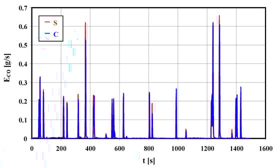
Figure 4.
Carbon monoxide emission rate in the Malta test for the standard engine (S) and for the engine with the internal catalyst (C).
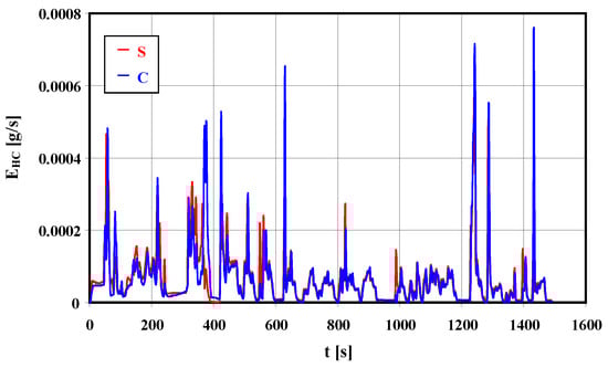
Figure 5.
Hydrocarbons emission rate in the Malta test for the standard engine (S) and for the engine with the internal catalyst (C).
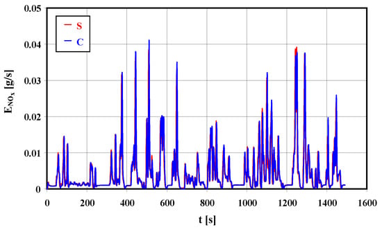
Figure 6.
Nitrogen oxides emission rate in the Malta test for the standard engine (S) and for the engine with the internal catalyst (C).
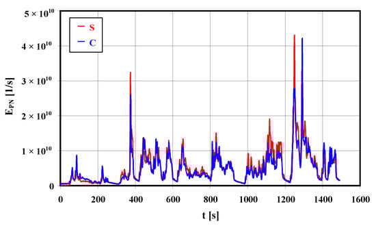
Figure 7.
Particle number emission rate in the Malta test for the standard engine (S) and for the engine with the internal catalyst (C).
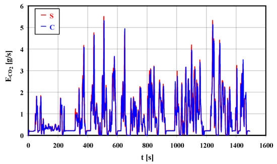
Figure 8.
Carbon dioxide emission rate in the Malta test for the standard engine (S) and for the engine with the internal catalyst (C).
As can be seen in Figure 4, Figure 5, Figure 6, Figure 7 and Figure 8, the characteristics of the pollutant emissions from the standard engine and the engine with the internal catalyst are very closely synchronized with each other, which indicates the high precision of the tests. The most sensitive to the operating conditions of the engine is the intensity of carbon monoxide and the least sensitive is carbon dioxide.
4. Test Results Analysis
Knowledge of the pollutant emission rates makes it possible to conduct time domain analyses of the efficiency of an internal catalyst in the reduction in exhaust emissions. Based on the obtained results, the emission of pollutants (m) and the number of particles (PN) during the test were determined (Figure 9, Figure 10, Figure 11, Figure 12 and Figure 13).
where m is the emission rate of x: CO, HC, NOx, CO2; PN is the particle number; t is time; and τ is the integration variable.
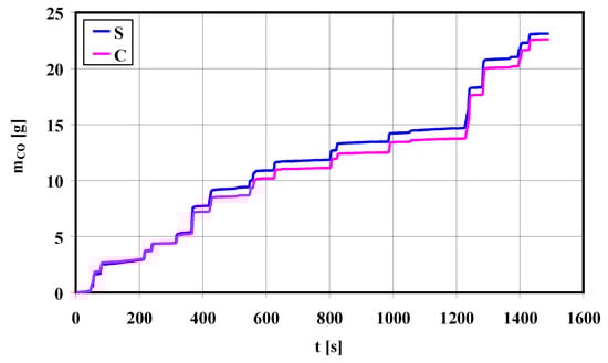
Figure 9.
Carbon monoxide emission in the Malta test for the standard engine (S) and for the engine with the internal catalyst (C).
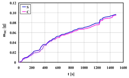
Figure 10.
Hydrocarbons emission in the Malta test for the standard engine (S) and for the engine with the internal catalyst (C).
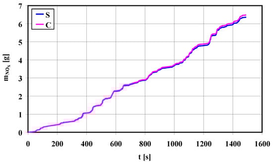
Figure 11.
Nitrogen oxides emission in the Malta test for the standard engine (S) and for the engine with the internal catalyst (C).
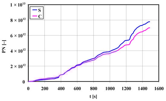
Figure 12.
Particle number in the Malta test for the standard engine (S) and for the engine with an internal catalyst (C).
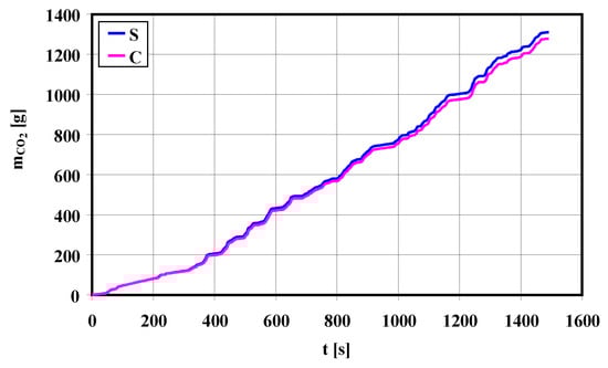
Figure 13.
Carbon dioxide emission in the Malta test for the standard engine (S) and for the engine with the internal catalyst (C).
The average value and standard deviation of the pollutant emission rate and the particle number emission rate were also determined (Table 2 and Figure 14, Figure 15, Figure 16, Figure 17 and Figure 18).
Table 2.
The average value (AV) and standard deviation (D) of the pollutant emission rate and the particle number emission rate for the standard engine (S) and for the engine with the internal catalyst (C).
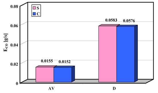
Figure 14.
Average value (AV) and standard deviation (D) of the carbon monoxide emission rate in the Malta test for the standard engine (S) and for the engine with the internal catalyst (C).
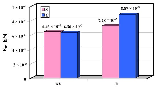
Figure 15.
Average value (AV) and standard deviation (D) of the hydrocarbons emission rate in the Malta test for the standard engine (S) and for the engine with the internal catalyst (C).
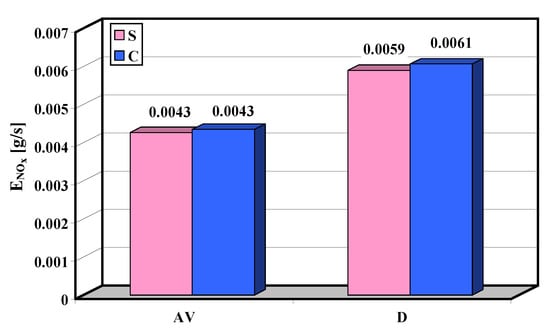
Figure 16.
Average value (AV) and standard deviation (D) of the nitrogen oxides emission rate in the Malta test for the standard engine (S) and for the engine with the internal catalyst (C).
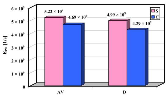
Figure 17.
Average value (AV) and standard deviation (D) of the particle number emission rate in the Malta test for the standard engine (S) and for the engine with the internal catalyst (C).
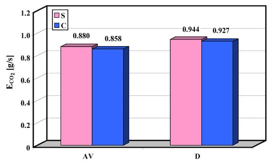
Figure 18.
Average value (AV) and standard deviation (D) of the carbon dioxide emission rate in the Malta test for the standard engine (S) and for the engine with the internal catalyst (C).
The emission rates of individual pollutants and the particle number are characterized by a high value of standard deviation that results from the high sensitivity of the emissions to both the stationary and dynamic operating conditions of the internal combustion engine. Figure 19 presents the coefficient of variation of the operating conditions along with the gaseous and particulate exhaust emissions.
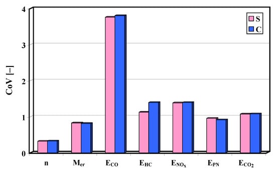
Figure 19.
Coefficient of variation of: engine speed, relative torque, and exhaust emission intensity in the Malta test for the standard engine (S) and for the engine with the internal catalyst (C).
Figure 14, Figure 15, Figure 16, Figure 17 and Figure 18 show a relative decrease in the emissions of carbon monoxide, hydrocarbons, carbon dioxide, and the particle number in the Malta test and an increase in the emission of nitrogen oxides (Figure 20).
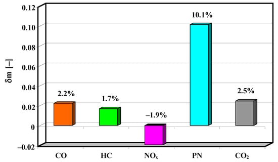
Figure 20.
Relative decrease in the average pollutant emission in the Malta test owing to the application of the internal catalyst.
The difference in the average value of the particle number emission rate in the Malta test for the standard engine and for the engine with the internal catalyst is significant in the t-Student test at a significance level of less than 0.001. The significance level of the difference of the average value of the other pollutants is greater than 0.99.
The strongest effect of the application of the internal catalyst is observed for particulate matter, leading to a relative decrease in the average particle number by more than 10%.
5. Conclusions
Based on the tests carried out on an internal combustion engine in its dynamic states, as determined by the vehicle operating conditions measured in the road test, the following conclusions can be made:
- The impact of the internal catalyst on the exhaust emissions is small (aside from the PN, the relative difference in the emission of other components is approx. 2%). It is, however, unambiguous and repeatable.
- The application of the internal catalyst reduced the emissions of carbon monoxide, hydrocarbons, carbon dioxide, and particulate matter. As a result of these changes (mainly the reduction in the emission of carbon dioxide), a reduction in the fuel consumption took place, and thus an increase in the overall engine efficiency. This can be explained by an increase in the engine thermal efficiency caused by an increase in the oxidation rate and, consequently, an increase in the heat release rate.
- The particle number was most affected by the use of the internal catalyst.
- Applying the internal catalyst increased the emission of nitrogen oxides.
It is possible to increase the catalyst-covered surface area by also applying it to other elements, such as injectors, valves, or piston crowns. It is also possible to improve the efficiency of the internal catalyst by increasing the glow plug heating time after engine cold start. Despite the small, but unambiguous and repeatable, impact of the use of the internal catalyst on the exhaust emissions from a compression-ignition engine under conditions simulating real vehicle driving, the results of the tests performed should be considered positive and promising for the successful development of the proposed solution.
Author Contributions
Conceptualization, M.A.-Z. and J.M.; methodology, Z.C.; software, J.P.; validation, Z.C. and M.A.-Z.; formal analysis, J.P.; investigations, J.M.; resources, J.P.; data curation, Z.C.; writing—original draft preparation, M.A.-Z.; writing—review and editing, Z.C.; visualization, M.A.-Z.; supervision, J.M.; project administration, J.M.; funding acquisition, J.P. All authors have read and agreed to the published version of the manuscript.
Funding
This research received no external funding.
Conflicts of Interest
The authors declare no conflict of interest.
References
- Eichner, T.; Pethig, R. Competition in emissions standards and capital taxes with local pollution. Reg. Sci. Urban Econ. 2018, 68, 191–203. [Google Scholar] [CrossRef]
- Serrano, J.R.; Arnau, F.J.; Martín, J.; Ángel, Á. Development of a variable valve actuation control to improve diesel oxidation catalyst efficiency and emissions in a light duty diesel engine. Energies 2020, 13, 4561. [Google Scholar] [CrossRef]
- Weber, C.; Sundvor, I.; Figenbaum, E. Comparison of regulated emission factors of Euro 6 LDV in Nordic temperatures and cold start conditions: Diesel- and gasoline direct-injection. Atmos. Environ. 2019, 206, 208–217. [Google Scholar] [CrossRef]
- Ko, S.; Park, J.; Kim, H.; Kang, G.; Lee, J.; Kim, J.; Lee, J. NOx emissions from Euro 5 and Euro 6 heavy-duty diesel vehicles under real driving conditions. Energies 2020, 13, 218. [Google Scholar] [CrossRef]
- Walkowiak, W.; Janicka, A.; Wróbel, R. Sposób wytwarzania świecy żarowej. Patent. Polska, nr 213284. Zgłoszenie nr 384930 z 14.04.2008, 28.02.2013, Politechnika Wrocławska. Available online: https://ewyszukiwarka.pue.uprp.gov.pl/search/pwp-details/P.384930 (accessed on 12 May 2020).
- Cao, X.; Vassenb, A.; Stoeverb, D. Ceramic materials for thermal barrier coatings. J. Eur. Ceram. Soc. 2004, 24(1), 1–10. [Google Scholar] [CrossRef]
- Diaz, P.M. Efficiency of nano ceramic coated and turbocharged internal combustion engine – A Review. J. Adv. Mech. Eng. Sci. 2017, 3, 1–13. [Google Scholar] [CrossRef]
- Andrych-Zalewska, M.; Chłopek, Z.; Merkisz, J.; Pielecha, J. Evaluation of the test drive cycle conditions impact on exhaust emissions from an internal combustion engine. Combust. Engines 2018, 175, 3–9. [Google Scholar] [CrossRef]
- Williams, K.; Schmidt, L. Cataytic autoignition of higher alkane partial oxidation on Rh-coated foams. Appl. Calatysis A Gen. 2006, 299, 30–45. [Google Scholar] [CrossRef]
- Bukatov, G.; Maslov, D.; Sergeev, S.; Matsko, M. Effect of internal donors on the performance of Ti-Mg catalysts in propylene polymerization: Donor introduction during or after MgCl2 formation. Appl. Catal. A Gen. 2019, 577, 69–75. [Google Scholar] [CrossRef]
- Ciniviz, M.; Sahir Salman, M.; Canli, E.; Köse, H. Ceramic coating applications and research fields for internal combustion engines. Ceram. Coat. Appl. Eng. 2012, 7, 195–234. [Google Scholar] [CrossRef]
- Merkisz, J.; Pielecha, J. Comparison of real driving emissions tests. IOP Conf Ser. Mater. Sci. Eng. 2018, 421, 042055. [Google Scholar] [CrossRef]
- Kurtyka, K.; Pielecha, J. The evaluation of exhaust emission in RDE tests including dynamic driving conditions. Transp. Res. Procedia 2019, 40, 338–345. [Google Scholar] [CrossRef]
- European Commission. (2017) Regulation (EC) 2017/1151 of 1 June 2017 supplementing Regulation (EC) No 715/2007 of the European Parliament and of the Council on type-approval of motor vehicles with respect to emissions from light passenger and commercial vehicles (Euro 5 and Euro 6) and on access to vehicle repair and maintenance information, amending Directive 2007/46/EC of the European Parliament and of the Council, Commission Regulation (EC) No 692/2008 and Commission Regulation (EU) No 1230/2012 and repealing Commission Regulation (EC) No 692/2008. Off. J. Eur. Un. 2017, 175, 1–643. [Google Scholar]
- Chłopek, Z. Synthesis of driving cycles in accordance with the criterion of similarity of frequency characteristics. Eksploat. i Niezawodn. Maint. Reliab. 2016, 18, 572–577. [Google Scholar] [CrossRef]
Publisher’s Note: MDPI stays neutral with regard to jurisdictional claims in published maps and institutional affiliations. |
© 2020 by the authors. Licensee MDPI, Basel, Switzerland. This article is an open access article distributed under the terms and conditions of the Creative Commons Attribution (CC BY) license (http://creativecommons.org/licenses/by/4.0/).