Abstract
Due to the poor thermal characteristics of the air, the absorber roughness of solar air collectors is commonly artificially increased in order to enhance the heat transfer to the air stream. However, this is also accompanied by an undesirable increase in the pumping power due to increased friction losses. As a result, several authors have experimentally investigated several ways of maximizing the heat transfer while minimizing the friction losses of different absorbers, resulting in the development of semi-empirical functions relating the Nusselt number (a measure of heat transfer) and the friction factor (a measure of friction losses) to the Reynolds number and the roughness parameters considered for each absorber. The present paper reviews, considering the publications from the last ten years, these semi-empirical functions. Moreover, the optimum roughness parameters and operating conditions of the absorbers were estimated by finding the maximum values of two performance parameters (the thermo-hydraulic efficiency and effectiveness), calculated using the semi-empirical functions, in order to classify the absorbers in terms of their energy characteristics. This approach proves to be a rather effective way of optimizing the roughness characteristics of solar air collector absorbers. It is also concluded that, considering the range of absorbers analyzed here, generally, multiple V-shaped ribs with gaps provide the most effective roughness geometry.
1. Introduction
The importance of solar thermal energy may be appreciated by the fact that, worldwide, the aggregate surface area of all collector units used for solar thermal conversion was, in 2018, , resulting in an installed capacity of (i.e., an increase of compared to the year 2000). In annual terms, of solar thermal energy were produced in 2018, corresponding to savings of of CO2 [1].
Solar air heaters are a solar thermal technology with a great potential. They have been used in a wide range of thermal energy applications that require low to moderate air temperatures, such as space heating, drying, and air preheating [2,3,4,5]. Solar air heating systems use air as the working fluid for absorbing and transferring solar energy, i.e., the available solar radiation is captured by an absorbing medium, which then heats the air through forced convection.
The main advantages of air heating systems are the following [6,7,8]: air is non-toxic, non-corrosive, it does not freeze or boil, and it does not spill or need to be replaced; in hot air applications, such as space heating or drying, there is no need for a heat exchanger, since air is the only working fluid.
The major disadvantages of solar air systems are related to the low volumetric heat capacity and low heat transfer characteristics of the air, which have to be compensated by large volume flow rates and large turbulence levels of the air stream, causing relatively high air-pumping costs. In addition, as air systems are comparatively difficult to seal, air leakages can represent a significant energy loss from the system [6,7,8].
As shown in Figure 1, a typical solar air heater comprises the following main elements [7,8,9]: a collection unit (usually, a flat-plate collector) to convert solar radiation into usable thermal energy (heated air), a storage unit (normally, a pebble bed) for the accumulation of thermal energy, and an auxiliary heater to compensate for energy shortfalls. These elements are interconnected by ducts, through which the air flows by means of a blower. Depending on the availability of energy and on the load demand, solar air heaters generally operate according to three main modes [7]:
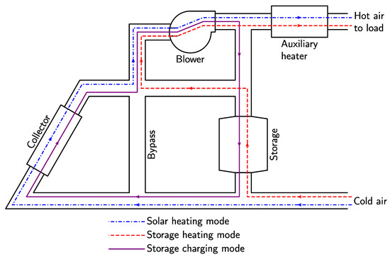
Figure 1.
Main elements and working modes of a solar air heater.
- Solar heating mode
- When the load requires thermal energy, and there is solar energy available, this energy is collected in the solar collector, causing air to heat up, which is then directly delivered to the load.
- Storage heating mode
- When the load requires thermal energy, and there is no solar energy available, cold air is heated up in the storage unit, being then delivered to the load.
- Storage charging mode
- When the load does not require thermal energy, and there is solar energy available, this energy is collected in the solar collector, causing air to heat up, which is then transferred to the storage unit.
Generally, the air heating process takes place in the following order: first, cold air is blown through the solar collectors in order to collect solar energy; if there is not enough energy to attend the load demand, then cold air is blown through the storage unit to recover previously accumulated energy; finally, if there is still not enough energy, the auxiliary heater is used to attend the load demand [7].
Two basic schemes are typically used to control the air flow [7,8]: on-off control, where the air flow rate is fixed and either turned on or off, depending on the air temperature at the collector outlet, and proportional control, where the flow rate is continuously varied so as to keep at a predetermined value the air temperature at the collector outlet. Per unit collector area, typical air flow rates are of the order of [7,10]. Furthermore, although the proportional control scheme performs slightly better than the on-off type, it normally consumes more electrical energy to pump the air [7]. In any case, the on-off control scheme is much more commonly used in solar air heating systems [8].
1.1. Collector unit
Flat-plate collectors are typically used in solar air heating systems and are composed by the following main elements (Figure 2) [3,11,12,13]: a transparent top cover (one or two transparent plates to create a separation between the ambient air and the air being heated), an absorber (typically, a blackened plate to collect solar radiation), and an insulated back casing. Air circulates in contact with the absorber to extract, through forced convection, its collected energy; the transparent cover reduces convection and radiation heat losses from the absorber to the atmosphere, while still allowing the solar radiation to reach the absorber; the insulated case reduces back conduction losses to the surroundings [8,13,14].
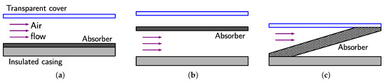
Figure 2.
Solar air collector. (a) Air flow above the absorber. (b) Air flow below the absorber. (c) Air flow through the absorber (porous absorber).
Solar air collectors may be categorized, according to their absorber types, as non-porous, if the air stream does not flow through the absorber (only above and/or below the absorber surface, as shown in Figure 2a,b), or porous, if the air stream flows through the absorber (Figure 2c) [7,12,14,15].
In order to compensate for the poor heat transfer characteristics of the air, the absorber must be designed in such a way to maximize the heat transfer from the absorber to the air stream. This is mainly achieved by increasing the turbulence of the air inside the collector and the heat transfer area of the absorber [2,11,15]. In non-porous absorbers, this is done by modifying the absorber plate with fins, obstacles, roughened surfaces, or corrugated surfaces. Porous absorbers use porous materials, such as wire meshes or perforated plates, to enhance the heat transfer characteristics of the absorber [3,12,15].
1.2. Storage Unit
Since solar energy is an intermittent resource, a thermal storage unit is necessary to meet the load demand whenever the solar radiation is not enough or is unavailable (e.g., during cloudy days or at night). In solar air heating, the usual energy storage media is a packed bed of small rocks or crushed gravel, i.e., the so-called pebble-bed storage [8]. Other storage media are also possible, such as water, the thermal mass of buildings, or phase-changing materials [12].
Pebble-bed units use the heat capacity of the bed material to store energy by circulating air though the bed to add or remove energy. When charging, hot air from the collector unit enters through the top of the bed, it flows downwards, heating up the pebbles, resulting in a stratified temperature distribution (i.e., a decreasing temperature gradient from the top to the bottom of the bed). When discharging, cold air enters through the bottom of the bed, it heats up as it flows upwards through the hot pebbles, causing the bed to release its stored energy [12,16].
An important advantage of pebble-bed storage systems is their high degree of thermal stratification, which results in low collector inlet temperatures and, consequently, in high collector efficiencies. In addition, the material of the bed is low-cost, easy to handle, non-toxic, and non-combustible. Other advantages include the possibility of high storage temperatures, and the fact that heat exchangers can be avoided [16,17].
One limitation of pebble-bed systems is that they cannot be charged and discharged simultaneously. In addition, the storage volumes have to be relatively large, and the pressure drop across the bed can be relatively high [16,17].
1.3. Energy Analysis
As shown schematically in Figure 3, the available solar irradiance () reaches the top surface of the collector, crosses its transparent cover, but only a fraction () is absorbed, causing an increase of the average temperature () of the absorber. Due to the temperature difference between the absorber and the external ambient air, thermal energy is, per unit of collector area, lost to the ambient due to conduction through the back casing and radiation and convection through the top transparent cover. An energy-efficient solar collector should absorb the incident solar radiation, convert it to thermal energy, and deliver it to the air stream with minimum losses [8,12].
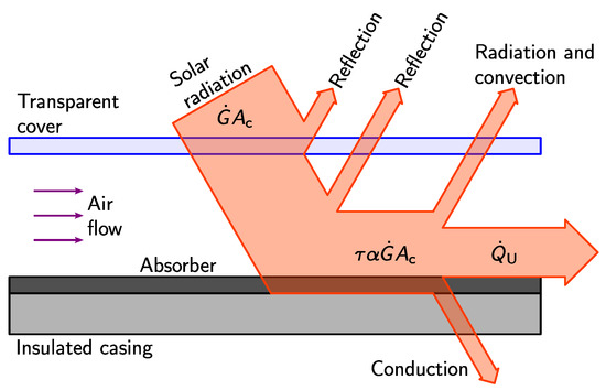
Figure 3.
Energy fluxes in solar collector.
Therefore, under steady-sate conditions, considering the heat fluxes on the absorber plate, the rate of useful energy collected by the air within a collector with area may be estimated as follows [8,12]:
where is the effective transmittance-absorbance product of the combined effect of the transparent cover and the absorber, is the absorber heat-loss coefficient based on the collector area, and is the ambient air temperature outside the collector.
The problem with Equation (1) is that, in most regular situations, average temperature is difficult to calculate or measure [8]. Therefore, an alternative equation, not dependent on , may be derived to express the useful heat transfer as a function of mid-range air temperature , where and are the air temperatures at the inlet and outlet of the collector, respectively [2,8]:
where is the collector efficiency factor, defined as the ratio of the actual value of to the value of that would be obtained if, for the whole absorber, temperature . Furthermore, considering the interaction between the absorber plate and the air system, as , it is not difficult to show that
where h is the coefficient of convection between the absorber surface and the air stream.
1.4. Work Objectives
As previously mentioned in Section 1.1, in solar air heaters, the convective heat transfer from the absorber surface to the air stream may be improved by either increasing the heat transfer surface area, using extended or corrugated surfaces, or by increasing the heat transfer coefficient, using artificial roughness on the absorber surface to promote turbulence in the air stream. However, this increase in heat transfer is also accompanied by an undesirable increase in the pumping power due to increased friction losses. Therefore, the design of the absorber surface should be implemented with the aim of maximizing heat transfer but minimizing friction losses [2,11,13,15,18,19,20].
As a result, several authors have experimentally investigated different ways of maximizing heat transfer by artificially modifying, using different techniques, the roughness characteristics of the exposed surface of the absorber, while minimizing friction losses. These studies often resulted in the development of semi-empirical functions relating the Nusselt number (a measure of heat transfer) and the friction factor (a measure of friction losses) to the Reynolds number (a measure of operating conditions) and the variable roughness parameters considered for each absorber [2,11,18,19,20].
The main objective of the present work is to review the aforementioned semi-empirical functions that were published in the last decade. It is also intended to use the outputs of these semi-empirical functions to evaluate the application of two performance parameters, i.e., the thermo-hydraulic efficiency and the thermo-hydraulic effectiveness, commonly used to compare the performance between different roughened absorber types or to find the optimum roughness parameters and operating conditions of a particular absorber design.
Section 2 describes the experimental procedure used by most researchers to obtain the data used to estimate heat transfer and friction losses in roughened ducts; it also describes the data processing methodology and defines both thermo-hydraulic performance parameters. Section 3 reviews the semi-empirical functions, it groups the absorbers into different roughness categories, and it classifies the absorbers according to their thermo-hydraulic performance. Finally, Section 4 compares the thermo-hydraulic performance between the best absorbers from the different categories defined in Section 3 and summarizes the main conclusions of the work.
2. Data Collection and Analysis
In turbulent flow, a laminar viscous sub-layer is developed adjacent to the heat transfer surface, causing a reduction in the heat transfer coefficient. The artificial roughness breaks up the viscous sub-layer and increases the turbulence adjacent to the heat transfer surface [21]. However, although the artificial roughness results in an advantageous increase in heat transfer, it also causes an undesirable increase in pumping power due to increased friction [2,11,13,18,19,20].
A solar air heater may be simulated as a rectangular duct having one rough surface, representing the absorber, and three smooth walls. Although the heat transfer and friction losses on a roughened duct may be investigated by analytical means, due to the complexity of the problem, many researchers have focused their attention on experimental investigations.
The experimental procedure and data analysis methods reviewed in this section to calculate heat transfer and friction losses in roughened ducts are essentially the same as those used to collect and process the data used in the derivation of the semi-empirical models described in Section 3. Detailed descriptions of the experimental procedures can be found, for example, in the works of Alam et al. [22] or Chamoli and Thakur [23]; a review paper by Yadav and Thapak [11] presents several schematic diagrams showing the experimental procedures employed by different researchers.
2.1. Experimental Procedture
Generally, the experimental procedure involves heating the absorber under test, forcing air to flow over the roughened surface of the absorber, and measuring, under steady-state conditions, the absorber temperature and the temperature rise and the pressure drop of the air. As shown in Figure 4, a typical test rig is composed by the following main elements: an electric heater placed under the unexposed surface of the absorber, a blower to promote air flow, and a duct system to direct the air over the absorber surface being tested.
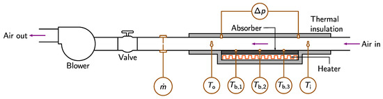
Figure 4.
Experimental set-up configuration for absorber testing.
As a minimum, the following measurements are necessary for the analysis of the energy interactions between the absorber and the air stream: The temperatures (, where ) at different locations of the exposed surface of the absorber, the temperatures of the air before and after the absorber ( and , respectively), the pressure drop () of the air along the entire length of absorber, and the mass flow rate () of the air. The temperatures measured at different locations of the absorber surface can then be used to estimate its average temperature:
2.2. Data Processing
A process of data reduction is typically applied to the experimental data by computing three dimensionless parameters: the average Reynolds number (), the average Nusselt number (), and the average Fanning friction factor (f) [21,24]. The Reynolds number is written as
the Nusselt number as
and the friction factor as
where , , and k are the average density, dynamic viscosity, and conductivity of the air, respectively, is the average speed of the air stream, L is the length of the absorber, and D is the hydraulic diameter. For rectangular ducts with non-porous absorbers,
where and are the cross-section area and perimeter of the duct, respectively, W is the width of the absorber, and H is the height of the duct.
For the calculation of , the convection coefficient may be readily obtained using the useful heat gain and the difference between the average absorber temperature and the mid-range air temperature:
Useful heat gain can be calculated using the air temperature rise along the heated section of the absorber:
where is the average specific heat capacity of the air at constant pressure.
2.3. Thermo-Hydraulic Performance
The most straightforward energy performance parameter of a solar thermal collector is its thermal efficiency (), which is based on the useful collected energy and the available solar irradiance [8,12]:
However, as mentioned before, in solar air collectors, the low heat transfer between the absorber and the air stream and the low volumetric heat capacity of the air have to be compensated by, respectively, high turbulence levels and high volume flow rates, resulting in increased friction losses. As a result, additional hydraulic energy is required, which has to be supplied by the blower at the expense of electrical energy [2,15,18].
Therefore, the energy performance of a solar collector has to be evaluated based on maximum thermal gains and minimum friction losses and cannot be, therefore, uniquely quantified by its thermal efficiency.
2.3.1. Thermo-Hydraulic Efficiency
The thermo-hydraulic efficiency () of the collector, introduced by Cortés and Piacentini [25] as the effective efficiency, incorporates both thermal gains and hydraulic losses and is a good indicator of the thermo-hydraulic performance of solar air heating systems [2,15,18,20,26,27,28]:
where is the hydraulic power needed to circulate the air, and represents the conversion efficiency from primary thermal energy to the mechanical energy used for air pumping. Parameter was introduced since the final cost (including production, transport, distribution, and final conversion) of electrical energy is much higher than that of thermal energy [25]. Furthermore, the hydraulic power is the product of the volume flow rate () and the pressure drop of the air flow [15,18]:
The problem with efficiency is that it does not dependent only on the thermal properties of the collector, but, due to the dependency of on , it also depends on collector-independent parameters, i.e., irradiance and temperature difference , as stated by Equation (2).
2.3.2. Thermo-Hydraulic Effectiveness
The thermo-hydraulic effectiveness () of the collector, introduced by Webb and Eckert [29], is another thermo-hydraulic performance parameter, which is not dependent on any collector-independent parameter; it takes into account both increased heat transfer and friction losses of an artificially roughened absorber and, for the same pumping power, relates these values to those of a smooth absorber [2,11,15,20,30,31,32,33,34,35]:
where and are the Nusselt numbers of the roughened and smooth ducts, respectively, and f and are the friction factors of the roughened and smooth ducts, respectively. A thermo-hydraulic effectiveness ensures that the roughened duct under consideration performs better than a smooth duct.
3. Semi-Empirical Modeling
The values of heat transfer and friction losses, obtained experimentally for different absorbers using the experimental procedure described in Section 2.1, were used by several researchers to develop, through regression analysis, semi-empirical models correlating both heat transfer and friction losses to the operating conditions of the collector and the roughness characteristics of the absorber.
Heat-transfer modeling was achieved through the development of mathematical functions relating the Nusselt number to the Reynolds number and parameters associated with the roughness of the absorber. Section 3.2 presents these functions, which generally take the following form:
where are non-dimensionalized roughness parameters, whose values are varied during the experiments, N is the number of roughness parameters, and b, , , and are free parameters obtained by regression analysis using the data from the experimental procedure.
Similarly, for friction-loss modeling, the friction factor was set as a function of the Reynolds number and parameters related to the absorber roughness. As stated in Section 3.2, these functions generally take the following form:
where are the same non-dimensionalized roughness parameters as those in Equation (12), and c, , , and are free parameters obtained by regression analysis using the data from the experimental procedure.
Although, in the derivation of the semi-empirical models presented in Section 3.2, the air properties are normally a function of the mid-range air temperature, in the present work, in order to simplify the calculations, all air properties were obtained for [24]: , , , and .
3.1. Performance Parameters
The two performance parameters described in Section 2.3.1 and Section 2.3.2 were used to quantify the energy performance of the absorbers whose models are presented throughout Section 3.2.
3.1.1. Maximum Thermo-Hydraulic Effectiveness
For a given value of , effectiveness was computed by means of Equation (11) and values of and f using the semi-empirical functions presented in Section 3.2 for different absorber designs. The Nusselt number and friction factor for a smooth duct were obtained using the Dittus–Boelter equation [24] and the Blasius equation [21], respectively, as proposed by Yadav and Thapak [11]:
valid for and , and
valid for , where is the Prandtl number.
Since, as stated by Equation (11), is a function of and f, and, as stated by Equations (12) and (13), and f are, in turn, functions of variable parameters , values of the maximum thermo-hydraulic effectiveness () were estimated for different values of and for each semi-empirical function presented in Section 3.2:
subjected to , where and are the lower and upper limits, respectively, of parameters , and . Maximum effectiveness was computed as a function of using box-constrained optimization with package Optim [36], a package for univariate and multivariate optimization in programming language Julia [37].
3.1.2. Maximum Thermo-Hydraulic Efficiency
The computation of efficiency is slightly more complex and needs additional data on the solar irradiance and some geometric and thermal characteristics of the solar collector; according to Equation (9), it basically involves, for a given value of , the calculation of useful heat rate and hydraulic power using values of and f calculated with the semi-empirical functions presented in Section 3.2.
Considering that inlet temperature (i.e., external ambient air is directly blown into the collector inlet), so that , solving Equations (2), (4), (7), and (8) simultaneously, the following equation may be derived for the rate of useful energy absorbed by the air stream:
where can be calculated using Equation (3), and convection coefficient h can be computed by means of Equation (5) for values of obtained from the semi-empirical functions.
Using values of f obtained using the semi-empirical functions, the following equation for the hydraulic power may be obtained by solving Equations (4), (6), and (10) simultaneously:
Two solar irradiance levels and the same typical values used by Mittal et al. [18] were used for the evaluation of : and , , , , , , and . Furthermore, it was assumed that the collector area is equal do the area of the absorber, i.e., .
In view of Equations (9), (14), and (15), since is a function of and f, and and f are functions of variable parameters , values of the maximum thermo-hydraulic efficiency () were estimated for different values of and for each semi-empirical function presented in Section 3.2:
subjected to , where . The optimum values of (represented by ) for which were also evaluated. Moreover, a performance parameter independent of was estimated by means of the maximum value of :
subjected to and , where and are the lower and upper limits, respectively, of , and . The optimum value of (represented by ) for which was also evaluated. As before, maximum efficiencies and were computed using box-constrained optimization with package Optim [36].
3.2. Nusselt Number and Friction Factor
This section presents and comparatively reviews, using the performance parameters presented in Section 3.1, the most relevant semi-empirical models published in the last decade; these models relate, as aforementioned, the Nusselt number and the friction factor to the Reynolds number and to other dimensionless roughness parameters related to different absorber designs. The different roughness surfaces were created by producing ribs and other types of obstacles of different geometries and dimensions on the exposed surface of the absorbers. The models are grouped, according to the roughness type, into straight ribs, curved ribs, round obstacles, and other obstacle types.
3.2.1. Straight Ribs
Straight ribs are made of straight metal wires of different diameters, attached to the exposed surface of the absorber, usually oriented diagonally with respect to the direction of air flow. Figure 5 shows the rib arrangement and roughness parameters of the different straight-rib absorbers presented in this section. The following roughness parameters are common to all straight-rib models: The height (e) of the rib, which, for circular wire ribs, equals the thickness of the rib, the longitudinal pitch (p), i.e., the distance between two consecutive ribs in the flow direction, and the attack angle (), i.e., the angle between the rib and flow directions.
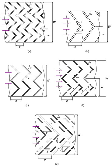
Figure 5.
Rib arrangement and roughness parameters of absorber plates with straight ribs. (a) Hans et al. [38]. (b) Singh et al. [39]. (c) Lanjewar et al. [40]. (d) Kumar et al. [41]. (e) Deo et al. [42].
Hans et al. [38] used aluminum wires to investigated the effect of different configurations of multiple V-shaped ribs with the apex facing downstream. As shown in Figure 5a, in addition to the parameters defined at the beginning of the current section, the width (w) of each V-shaped rib was also regarded as a roughness parameter. In addition to , dimensionless parameters , , , and were selected as the independent variables for the derivation of the following semi-empirical functions:
and
These functions are valid for the following ranges: , , , , and . Table 1 presents the values of and optimum parameters , , , and for , , and .

Table 1.
Maximum efficiency and optimum roughness parameters according to the model developed by Hans et al. [38].
Singh et al. [39] investigated the effect of single V-shaped ribs having two small gaps located symmetrically on both legs of each rib. The ribs were produced using aluminum wires with the apex facing downstream. As shown in Figure 5b, in addition to the parameters defined at the beginning of this section, the following roughness parameters were also considered: the gap distance (j) from the side of the rib, measured perpendicular to the flow direction, and the gap width (g). In addition to , dimensionless parameters , , , , where , and were selected as the independent variables for the derivation of the following semi-empirical functions:
and
These functions are valid for the following ranges: , , , , , and . Table 2 presents the values of and optimum parameters , , , , and for , , and .
Table 2.
Maximum efficiency and optimum roughness parameters according to the model developed by Singh et al. [39].
Lanjewar et al. [40] used copper wires to produce absorbers with W-shaped ribs. As shown in Figure 5c, this rib shape corresponds, in effect, to two V-shaped ribs placed side by side with the apex pointing downstream, i.e., a particular case of the absorber investigated by Hans et al. [38]. Moreover, from the parameters defined at the beginning of this section, the authors fixed the relative pitch . Hence, in addition to , only dimensionless parameters and were selected as the independent variables for the derivation of the following semi-empirical functions:
and
These functions are valid for the following ranges: , , and . Table 3 presents the values of and optimum parameters and for , , and .
Table 3.
Maximum efficiency and optimum roughness parameters according to the model developed by Lanjewar et al. [40].
Kumar et al. [41] produced, using aluminum wires, an absorber based on the design by Hans et al. [38], i.e., multiple V-shaped ribs, and also on the design by Singh et al. [39], i.e., having two small gaps located symmetrically on both legs of the ribs. As shown in Figure 5d, in addition to the parameters defined at the beginning of this section, the following roughness parameters were also considered: the width (w) of each rib, the gap distance (j) from the side of each rib, measured along the length of the rib, and the gap width (g). In addition to , dimensionless parameters , , , , , where l is the distance, measured along the ribs, from the side to the midpoint of the ribs, and were selected as the independent variables for the derivation of the following semi-empirical functions:
and
These functions are valid for the following ranges: , , , , , , and . Table 4 presents the values of and optimum parameters , , , , , and for , , and .
Table 4.
Maximum efficiency and optimum roughness parameters according to the model developed by Kumar et al. [41].
Deo et al. [42] used aluminum wires to produce single V-shaped ribs having four gaps, placed symmetrically on the legs of each rib, having a staggered rib placed in front of each gap. As shown in Figure 5e, in addition to the parameters defined at the beginning of this section, the authors also considered the following roughness parameters: The length (j) of each staggered rib, measured perpendicular to the flow direction, the distance (q) between V-shaped and staggered ribs, measured in the flow direction, and the gap width (g). However, the following dimensionless parameters were kept constant: , , and . As a result, in addition to , only dimensionless parameters , , and were selected as the independent variables for the derivation of the following semi-empirical functions:
and
These functions are valid for the following ranges: , , , and . Table 5 presents the values of and optimum parameters , , and for , , and .
Table 5.
Maximum efficiency and optimum roughness parameters according to the model developed by Deo et al. [42].
Figure 6 and Figure 7 show the variation of efficiency with for and , respectively; Figure 8 shows the variation of effectiveness with . The values of and were computed for varying between 3000 and 18000, regardless of the limits and valid for each model. For all models, increases with increasing when is low, reaching maximum value when , from which starts decreasing with further increasing . However, effectiveness increases monotonically with increasing for all values of
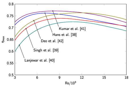
Figure 6.
Relationship between and for absorber plates with straight ribs and
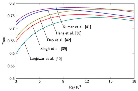
Figure 7.
Relationship between and for absorber plates with straight ribs and
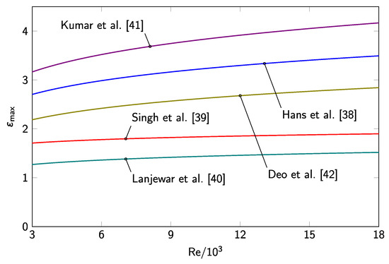
Figure 8.
Relationship between and for absorber plates with straight ribs.
Considering the values of maximum efficiency presented in Table 1, Table 2, Table 3, Table 4 and Table 5 for optimum values , it can be concluded that the absorber type investigated by Kumar et al. [41], i.e., multiple V-shaped ribs with gaps, outperforms all the other straight-rib absorbers. This conclusion is confirmed by the values presented in Figure 8, in which, for all values of , the value of effectiveness for this absorber is higher than that for all the other absorbers. For example, when , , , , , and for the absorbers investigated, respectively, by Kumar et al. [41], Hans et al. [38], Deo et al. [42], Singh et al. [39], and Lanjewar et al. [40].
Table 1, Table 2, Table 3, Table 4 and Table 5 and Figure 6, Figure 7 and Figure 8 also show that, especially for low values of , increasing roughness parameter above unity has a positive impact on the thermo-hydraulic performance of the absorbers, i.e., multiple V-shaped ribs perform better than single V-shaped ribs. Therefore, considering the two absorber designs with single V-shaped ribs and gaps, as the absorbers with staggered ribs [42] outperforms the absorber without staggered ribs [39], it may be inferred that an absorber with multiple V-shaped ribs having gaps and staggered ribs could probably also outperform the absorber without staggered ribs investigated by Kumar et al. [41]. Or you could also provide us a tex version which can show the cited refs on figures. Thank you for your cooperation.
3.2.2. Curved ribs
Curved ribs are made of arc-shaped metal wires of different diameters attached to the exposed surface of the absorber, in which the tangent to the arc midpoint is perpendicular to the air flow direction. Figure 9 shows the rib arrangement and roughness parameters of the different curved-rib absorbers presented in this section. The following roughness parameters are common to all curved-rib models: the height (e) of the rib, which, for circular wire ribs, equals the thickness of the rib, the longitudinal pitch (p), i.e., the distance between two consecutive ribs in the flow direction, and the arc angle (), i.e., the inscribed angle subtended by the arc of the ribs.
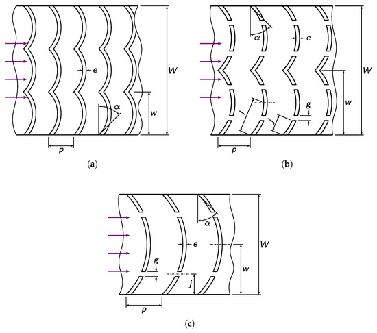
Figure 9.
Rib arrangement and roughness parameters of absorber plates with curved ribs. (a) Singh et al. [43]. (b) Pandey et al. [44]. (c) Hans et al. [34].
Singh et al. [43] used aluminum wires to investigated the effect of different configurations of multiple arc-shaped ribs with the convex curvature facing downstream. As shown in Figure 9a, in addition to the parameters defined at the beginning of the current section, the width (w) of each arc rib was also regarded as a roughness parameter. In addition to , dimensionless parameters , , , and were selected as the independent variables for the derivation of the following semi-empirical functions:
and
These functions are valid for the following ranges: , , , , and . Table 6 presents the values of and optimum parameters , , , and for , , and .
Table 6.
Maximum efficiency and optimum roughness parameters according to the model developed by Singh et al. [43].
Pandey et al. [44] investigated the effect of multiple arc ribs with two small gaps located symmetrically on each rib. The ribs were produced using aluminum wires with the convex curvature facing downstream. As shown in Figure 9b, in addition to the parameters defined at the beginning of this section, the authors also considered the following roughness parameters: the width (w) of each rib, the gap distance (j) from the side of each rib, measured along the rib arc, and the gap width (g). In addition to , dimensionless parameters , , , , , where l is the distance, measured along the arc, from the side to the midpoint of the ribs, and were selected as the independent variables for the derivation of the following semi-empirical functions:
and
These functions are valid for the following ranges: , , , , , , and . Table 7 presents the values of and optimum parameters , , , , , and ( for , , and .
Table 7.
Maximum efficiency and optimum roughness parameters according to the model developed by Pandey et al. [44].
Hans et al. [34] used aluminum wires to produce absorbers with single arc ribs having two small gaps located symmetrically on each rib. As shown in Figure 9c, this rib geometry corresponds, in effect, to the particular case in which of the absorber investigated by Pandey et al. [44]. In addition to the parameters defined at the beginning of this section, the authors also considered the following roughness parameters: the gap distance (j) from the side of each rib, measured perpendicular to the flow direction, and the gap width (g). In addition to , dimensionless parameters , , , , where , and were selected as the independent variables for the derivation of the following semi-empirical functions:
and
These functions are valid for the following ranges: , , , , , and . Table 8 presents the values of and optimum parameters , , , , and ( for , , and .
Table 8.
Maximum efficiency and optimum roughness parameters according to the model developed by Hans et al. [34].
Figure 10 and Figure 11 show the variation of efficiency with for and , respectively; Figure 12 show the variation of effectiveness with . As before, the values of and were computed for ranging from 3000 to 18000, regardless of the limits and valid for each model. For all models, increases with increasing when is low, reaching maximum value when , from which starts decreasing with further increasing . However, effectiveness increases continually with increasing for all values of
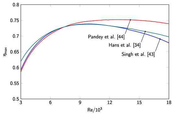
Figure 10.
Relationship between and for absorber plates with curved ribs and
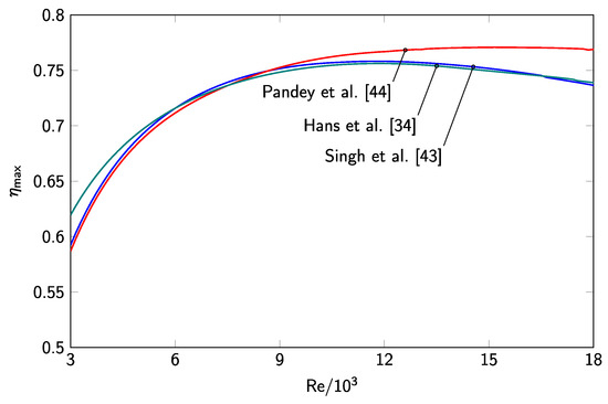
Figure 11.
Relationship between and for absorber plates with curved ribs and
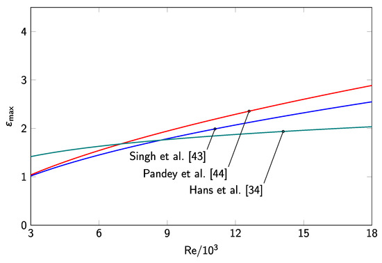
Figure 12.
Relationship between and for absorber plates with curved ribs.
Maximum efficiency presented in Table 6, Table 7 and Table 8 for optimum values show that the absorber investigated by Pandey et al. [44], i.e., multiple arc-shaped ribs with gaps, outperforms all the other curved-rib absorbers. This conclusion is confirmed by the values presented in Figure 12, in which, excluding the lowest values of , maximum effectiveness for this absorber is higher than that for the other two absorbers. For example, when , , , and for the absorbers investigated, respectively, by Pandey et al. [44], Singh et al. [43], and Hans et al. [34].
Finally, it is worth mentioning that Kumar et al. [45] also investigated the effect of arc-shaped ribs with a variable number of gaps. However, this work was not included in the preset analysis due to two reasons: the model is only valid for a rather limited range of Reynolds numbers (), and the semi-empirical functions developed for the Nusselt number and friction factor are quadratic polynomials that do not allow the convergence to a single maximum efficiency value.
3.2.3. Round obstacles
Round obstacles include circular-shaped interferences, both concave or convex, to the air stream, located on the exposed surface of the absorber. Figure 13 shows the obstacle arrangement and roughness parameters of the different round-obstacle absorbers presented in this section. The following roughness parameters are common to all models: the height or depth (e) of the obstacles, the longitudinal pitch (p), i.e., the distance between two consecutive obstacles in the flow direction, and the diameter (d) of the obstacles.
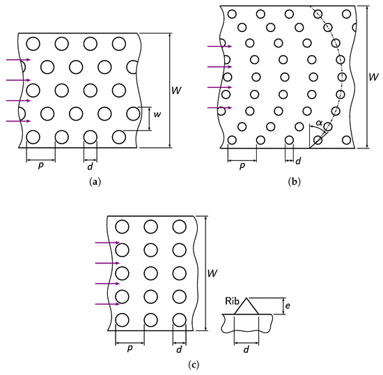
Figure 13.
Rib arrangement and roughness parameters of absorber plates with round obstacles. (a) Bhushan and Singh [46]. (b) Sethi et al. [47] and Yadav et al. [48]. (c) Alam and Kim [49].
Bhushan and Singh [46] investigated the effect of absorbers having circular protrusions, produced by indentation on the absorber plate. As shown in Figure 13a, the obstacles were arranged in rows of aligned protrusions, interspersed with staggered rows of protrusions. With respect to the roughness parameters defined at the beginning of this section, for this particular case, pitch p was defined as the distance between two consecutive rows of aligned protrusions; the transverse pitch (w), i.e., the distance between two consecutive aligned rows of protrusions, measured perpendicular to the flow direction, was also regarded as a roughness parameter. Dimensionless parameters was kept constant, and, in addition to , dimensionless parameters , , and were selected as the independent variables for the derivation of the following semi-empirical functions:
and
These functions are valid for the following ranges: , , , and . Table 9 presents the values of and optimum parameters , , and ( for , , and .
Table 9.
Maximum efficiency and optimum roughness parameters according to the model developed by Bhushan and Singh [46].
Acknowledging that both dimple-shaped elements and arc-shaped ribs outperform all other roughness types, Sethi et al. [47] developed an absorber plate with circular dimples, produced by indentation, located symmetrically along succeeding arcs, whose midpoint tangents are perpendicular to the flow direction, with the convex curvature facing downstream. As shown in Figure 13b, in addition to the parameters defined at the beginning of this section, the arc angle (), i.e., the inscribed angle subtended by the location arc of the dimples, was also regarded as a roughness parameter. Dimensionless parameters was kept constant, and, in addition to , dimensionless parameters , , and were selected as the independent variables for the derivation of the following semi-empirical functions:
and
These functions are valid for the following ranges: , , , and . Table 10 presents the values of and optimum parameters , , and for , , and .
Table 10.
Maximum efficiency and optimum roughness parameters according to the model developed by Sethi et al. [47].
Yadav et al. [48] investigated the effect of absorbers having circular protrusions, produced by indentation, located symmetrically along succeeding arcs, whose midpoint tangents are perpendicular to the flow direction, with the convex curvature facing downstream. As shown in Figure 13b, in addition to the parameters defined at the beginning of this section, the arc angle (), i.e., the inscribed angle subtended by the location arc of the protrusions, was also regarded as a roughness parameter. Dimensionless parameters was kept constant, and, in addition to , dimensionless parameters , , and were selected as the independent variables for the derivation of the following semi-empirical functions:
and
These functions are valid for the following ranges: , , , and . Table 11 presents the values of and optimum parameters , , and for , , and .
Table 11.
Maximum efficiency and optimum roughness parameters according to the model developed by Yadav et al. [48].
Alam and Kim [49] produced absorber plates with conical ribs, arranged, as shown in Figure 13c, in rows of aligned ribs. Although the authors stated that relative diameter was kept constant, its value was not disclosed. Hence, in addition to , dimensionless parameters and were selected as the independent variables for the derivation of the following semi-empirical functions:
and
These functions are valid for the following ranges: , , and . Table 12 presents the values of and optimum parameters and for , , and .
Table 12.
Maximum efficiency and optimum roughness parameters according to the model developed by Alam and Kim [49].
Figure 14 and Figure 15 show the variation of efficiency with for and , respectively; Figure 16 show the variation of effectiveness with . As before, the values of and were computed for ranging from 3000 to 18000, regardless of the limits and valid for each model. For all models, increases with increasing when is low, reaching maximum value when , from which starts decreasing with further increasing . However, effectiveness increases monotonically with increasing for all values of
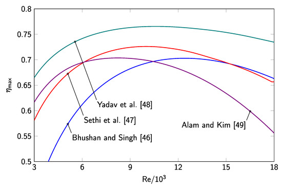
Figure 14.
Relationship between and for absorber plates with round obstacles and
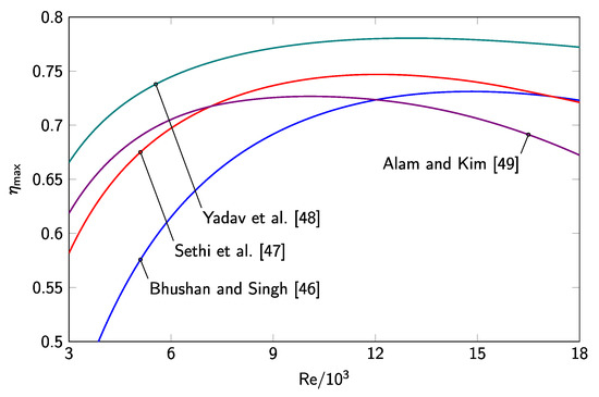
Figure 15.
Relationship between and for absorber plates with round obstacles and
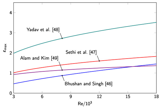
Figure 16.
Relationship between and for absorber plates with round obstacles.
The values of maximum efficiency presented in Table 9, Table 10, Table 11 and Table 12 for optimum values show that the absorber investigated by Yadav et al. [48] is the round-obstacle absorber with the best performance, followed by the absorber investigated by Sethi et al. [47]. In these two absorbers, the obstacles are located along succeeding arcs, but the obstacles of the first absorber are protrusions, whereas the obstacles of the second are dimples. This conclusion is confirmed by the values of maximum effectiveness presented in Figure 16. For example, when , , , , and for the absorbers investigated, respectively, by Yadav et al. [48], Sethi et al. [47], Alam and Kim [49], and Bhushan and Singh [46].
3.2.4. Other obstacle types
This section presents the absorber models whose roughness types are not covered by the previous three categories presented in Section 3.2.1, Section 3.2.2 and Section 3.2.3; the obstacle arrangement and roughness parameters are shown in Figure 17. One roughness parameter is common to all models: the longitudinal pitch (p), i.e., the distance between two consecutive obstacles in the flow direction.
Figure 17.
Rib arrangement and roughness parameters of absorber plates with other obstacle types. (a) Chauhan and Thakur [50]. (b) Gawande et al. [27]. (c) Chamoli et al. [51]. (d) Kumar and Layek [28].
Chauhan and Thakur [50] investigated the thermo-hydraulic characteristics of impingement jet solar air collectors with aligned round holes. As shown in Figure 17a, impingement jet collectors use a perforated plate (the impingement plate) to increase the air speed and direct the air against the absorber plate in order to enhance the heat transfer between the absorber and the air stream [5,15]. In this particular case, pitch p was defined as the distance between consecutive holes in the impingement plate; in addition, the following parameters were also considered: the transverse pitch (w), i.e., the distance between two consecutive holes, measured perpendicular to the flow direction, and the diameter (d) of the holes. In addition to , dimensionless parameters , , and were selected as the independent variables for the derivation of the following semi-empirical functions:
and
These functions are valid for the following ranges: , , , and . Table 13 presents the values of and optimum parameters , , and for , , and .
Table 13.
Maximum efficiency and optimum roughness parameters according to the model developed by Chauhan and Thakur [50].
Gawande et al. [27] investigated a new roughness geometry using reverse L-shaped ribs attached to the exposed surface of the absorber. As shown in Figure 17b, in addition to pitch p, the height (e) of the ribs, which, for this particular case, equals the thickness of the ribs, was also regarded as a roughness parameter. Dimensionless parameters was kept constant, and, in addition to , only dimensionless parameter was selected as the independent variable for the derivation of the following semi-empirical functions:
and
These functions are valid for the following ranges: and . Table 13 presents the values of and optimum parameter for , , and .
Chamoli et al. [51] investigated the effect of trapezoidal winglets attached perpendicularly to the absorber plate. As shown in Figure 17c, the winglets increase linearly in height along the downstream direction and are combined in symmetrical pairs with respect to the flow direction. In addition to pitch p, the following roughness parameters were also considered: the angle () of the winglets with the flow direction, the lowest height (s), the highest height (e), and the length (l) of the winglets. Dimensionless parameters and were kept constant, and, in addition to , dimensionless parameters and were selected as the independent variables for the derivation of the following semi-empirical functions:
and
These functions are valid for the following ranges: , , and . Table 14 presents the values of and optimum parameters and for , , and .
Table 14.
Maximum efficiency and optimum roughness parameters according to the model developed by Chamoli et al. [51].
Kumar and Layek [28] used parallel twisted ribs, perpendicular to the flow direction, to produce the artificial roughness on absorber plates. As shown in Figure 17d, in addition to pitch p, the following roughness parameters were also considered: the height (e) of the ribs, which, for a twisted rib, equals its thickness, the width (w) of each complete twist, the twist angle (), i.e., the inclination of the rib with respect to the flow direction. In addition to , dimensionless parameters , , and were selected as the independent variables for the derivation of the following semi-empirical functions:
and
These functions are valid for the following ranges: , , , and . Table 15 presents the values of and optimum parameters , , and for , , and .
Table 15.
Maximum efficiency and optimum roughness parameters according to the model developed by Kumar and Layek [28].
Figure 18 and Figure 19 show the variation of efficiency with for and , respectively; Figure 20 show the variation of effectiveness with . As before, the values of and were computed for ranging from 3000 to 18000, regardless of the limits and valid for each model. For all models, increases with increasing when is low, reaching maximum value when , from which starts decreasing with further increasing . For the models presented by Chauhan and Thakur [50], Gawande et al. [27], and Kumar and Layek [28], as before, effectiveness increases monotonically with increasing for all values of . However, for the model presented by Chamoli et al. [51], decreases monotonically with increasing .
Figure 18.
Relationship between and for absorber plates with other obstacle types and
Figure 19.
Relationship between and for absorber plates with other obstacle types and
Figure 20.
Relationship between and for absorber plates with other obstacle types.
The values of maximum efficiency presented in Table 13, Table 14, Table 15 and Table 16 for optimum values show that the absorber investigated by Chamoli et al. [51] outperforms all the other absorbers, and the one investigated by Gawande et al. [27] is the worst-performing absorber. This conclusion is confirmed by the values of maximum effectiveness presented in Figure 20. For example, when , , , , and for the absorbers investigated, respectively, by Chamoli et al. [51], Kumar and Layek [28], Chauhan and Thakur [50], and Gawande et al. [27].
Table 16.
Maximum efficiency and optimum roughness parameters according to the model developed by Gawande et al. [27].
Finally, it is worth mentioning that some modeling works, also developed during the last decade for different roughness types, were not analyzed herein, mainly because the experimental setup deviates considerably from the typical configuration of a rectangular duct with a single rough surface: Skullong and Promvonge [30] used triangle-shaped winglets to enhance the roughness of a collector having two absorber plates; Tamna et al. [32] investigated the effect of multiple thin V-shaped ribs attached to the absorber surfaces of a double-absorber collector; Skullong et al. [31] investigated the effect of absorbers with multiple V-shaped ribs, interspersed with straight grooves, oriented perpendicular to the flow direction, in a double-absorber collector; Acır et al. [33] investigated round-duct collectors containing inner ring-shaped plates with holes, perpendicular to the flow direction, to increase the turbulence of the air stream; Kumar et al. [35] studied the effect of straight ribs, perpendicular to the flow direction, attached to the absorber of a collector made of a triangle-shaped cross-section duct.
4. Concluding Remarks
Five collectors with the best thermo-hydraulic performance were selected in order to be comparatively analyzed: two collectors from Section 3.2.1 (straight ribs) and one collector from Section 3.2.2 (curved ribs), from Section 3.2.3 (round obstacles), and from Section 3.2.4 (other obstacle types). Figure 21 and Figure 22 show the variation of efficiency with for and , respectively; Figure 23 show the variation of effectiveness with .
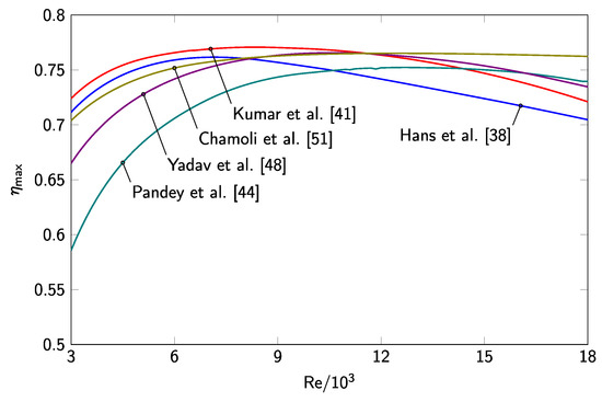
Figure 21.
Relationship between and for the best performing absorber plates and
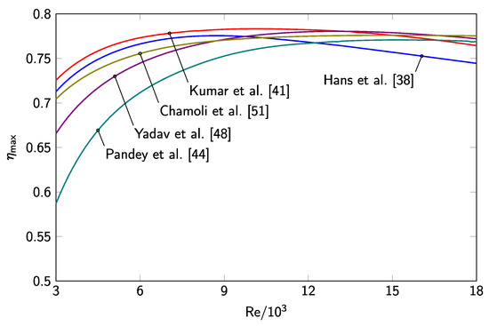
Figure 22.
Relationship between and for the best performing absorber plates and
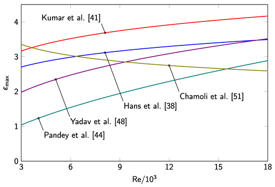
Figure 23.
Relationship between and for the best performing absorber plates.
With respect to maximum efficiency , three absorbers appear to have roughly equivalent performance: with and for and , respectively, the absorber with multiple V-shaped ribs and gaps investigated by Kumar et al. [41], the round-obstacle absorber with protrusions located along arcs investigated by Yadav et al. [48], and the absorber with trapezoidal winglets investigated by Chamoli et al. [51]; then, with and for and , respectively, it follows the absorber with V-shaped ribs investigated by Hans et al. [38]; finally, with and for and , respectively, it follows the curved-rib absorber with gaps investigated by Pandey et al. [44].
However, considering effectiveness , Figure 23 shows that the two straight-rib absorbers outperform all the other absorbers. When , for example, the most effective is the absorber by Kumar et al. [41] (), followed by, in order of decreasing effectiveness, the absorbers by Hans et al. [38] (), Chamoli et al. [51] (), Yadav et al. [48] (), and, finally, Pandey et al. [44] (). These results are in agreement with Kumar et al. [52], who also concluded that multiple V-shaped ribs with gaps outperform all the other roughness configurations.
In order to use parameter to compare the thermo-hydraulic performance of different absorbers, one has to assume that each absorber under consideration operates at its optimum value ; for different values of , different results may be obtained, since is strongly dependent on , and the shape of the relationship between and is different for different absorbers. However, although is also dependent on , the shape of the relationship between and is, in most cases, very similar for different absorbers. In any case, for collectors with reasonably distinguishable thermo-hydraulic performances, using or seems to produce comparable conclusions. Moreover, since efficiency exhibits a well-defined maximum when , this performance parameter can be used to select the ideal operating conditions for a particular absorber, namely the optimum flow rate of the air stream, which can be particularly useful in on-off control systems.
Funding
This research received no external funding.
Conflicts of Interest
The authors declare no conflict of interest.
Nomenclature
| Attack angle, arc angle, or twist angle () | |
| Generic free parameter of semi-empirical Nu function | |
| Generic free parameter of semi-empirial Nu function | |
| Generic free parameter of semi-empirical f function | |
| Generic free parameter of semi-empirical f function | |
| Thermo-hydraulic effectiveness of the collector | |
| Maximum thermo-hydraulic effectiveness as a function of | |
| Thermo-hydraulic efficiency of the collector | |
| Maximum thermo-hydraulic efficiency as a function of | |
| Absolute maximum thermo-hydraulic efficiency | |
| Thermal efficiency of the collector | |
| Conversion efficiency from thermal to mechanical energy | |
| Average dynamic viscosity of the air () | |
| Average density of the air () | |
| Transmittance-absorptance product of the collector | |
| Pressure drop of the air stream () | |
| b | Generic free parameter of semi-empirical Nu function |
| Generic free parameters of semi-empirical Nu function | |
| c | Generic free parameter of semi-empirical f function |
| Generic free parameter of semi-empirical f function | |
| Average specific heat capacity of the air at constant pressure () | |
| d | Diameter of obstacle or hole () |
| e | Rib height, obstacle height or depth, or highest height of winglet () |
| f | Average friction factor3 |
| Friction factor of a smooth absorber | |
| g | Gap width () |
| h | Convection coefficient () |
| j | Gap distance or length of staggered rib () |
| k | Average conductivity of the air () |
| l | Half the rib length or winglet length () |
| Mass flow rate of the air stream () | |
| n | Parameter index3 |
| p | Longitudinal pitch () |
| q | Distance to staggered ribs () |
| s | Lowest height of winglet () |
| u | Average speed of the air stream () |
| w | Rib width or transverse pitch () |
| Generic dimensionless roughness parameter n | |
| Optimum generic roughness parameter | |
| Upper limit of generic roughness parameter | |
| Lower limit of generic roughness parameter | |
| A | Cross-section area of the collector duct () |
| Collector area () | |
| D | Hydraulic diameter of the collector duct () |
| Collector efficiency factor | |
| Solar irradiance () | |
| H | Height of the collector duct () |
| L | Length of the absorber () |
| N | Number of dimensionless roughness parameters |
| Number of absorber temperature measurements | |
| Average Nusselt number | |
| Nusselt number of a smooth absorber | |
| P | Cross-section perimeter of the collector duct () |
| Prandtl number | |
| Useful heat gain () | |
| Average Reynolds number | |
| Optimum | |
| Upper limit of | |
| Lower limit of | |
| Ambient temperature () | |
| Average temperature of the absorber () | |
| Absorber temperature n () | |
| Mid-range temperature of the air stream () | |
| Inlet temperature of the air stream () | |
| Outlet temperature of the air stream () | |
| Heat-loss coefficient of the collector () | |
| Volume flow rate of the air stream () | |
| W | Width of the absorber () |
| Pumping power () |
References
- Weiss, W.; Spörk-Dür, M. Solar Heat Worldwide: Global Market Development and Trends in 2018; AEE INTEC: Gleisdorf, Austria, 2019. [Google Scholar]
- Kumar, A.; Saini, R.P.; Saini, J.S. A review of thermohydraulic performance of artificially roughened solar air heaters. Renew. Sustain. Energy Rev. 2014, 37, 100–122. [Google Scholar] [CrossRef]
- Kabeel, A.E.; Hamed, M.H.; Omara, Z.M.; Kandeal, A.W. Solar air heaters: Design configurations, improvement methods and applications—A detailed review. Renew. Sustain. Energy Rev. 2017, 70, 1189–1206. [Google Scholar] [CrossRef]
- Bezbaruah, P.J.; Das, R.S.; Sarkar, B.K. Overall performance analysis and GRA optimization of solar air heater with truncated half conical vortex generators. Sol. Energy 2020, 196, 637–652. [Google Scholar] [CrossRef]
- Singh, S.; Chaurasiya, S.K.; Negi, B.S.; Chander, S.; Nemś, M.; Negi, S. Utilizing circular jet impingement to enhance thermal performance of solar air heater. Renew. Energy 2020, 154, 1327–1345. [Google Scholar] [CrossRef]
- Garg, H.P. Advances in Solar Energy Technology: Volume 1, Collection and Storage Systems; Reidel: Dordrecht, The Netherlands, 1987. [Google Scholar]
- Garg, H.P. Advances in Solar Energy Technology: Volume 2, Industrial Applications of Solar Energy; Reidel: Dordrecht, The Netherlands, 1987. [Google Scholar]
- Duffie, J.A.; Beckman, W.A. Solar Engineering of Thermal Processes, 4th ed.; Wiley: Hoboken, NJ, USA, 2013. [Google Scholar] [CrossRef]
- Kalogirou, S.A.; Florides, G.A. Solar space heating and cooling systems. In Comprehensive Renewable Energy, Volume 3; Sayigh, A., Ed.; Elsevier: Oxford, UK, 2012; Chapter 3.13; pp. 449–480. [Google Scholar] [CrossRef]
- Caouris, Y.G. Low Temperature Stationary Collectors. In Comprehensive Renewable Energy, Volume 3; Sayigh, A., Ed.; Elsevier: Oxford, UK, 2012; Chapter 3.04; pp. 103–147. [Google Scholar] [CrossRef]
- Yadav, A.S.; Thapak, M.K. Artificially roughened solar air heater: Experimental investigations. Renew. Sustain. Energy Rev. 2014, 36, 370–411. [Google Scholar] [CrossRef]
- Kalogirou, S.A. Solar Energy Engineering: Processes and Systems, 2nd ed.; Academic Press: Oxford, UK, 2014. [Google Scholar]
- Arunkumar, H.S.; Karanth, K.V.; Kumar, S. Review on the design modifications of a solar air heater for improvement in the thermal performance. Sustain. Energy Technol. Assessments 2020, 39, 100685. [Google Scholar] [CrossRef]
- Saxena, A.; Varun; El-Sebaii, A.A. A thermodynamic review of solar air heaters. Renew. Sustain. Energy Rev. 2015, 43, 863–890. [Google Scholar] [CrossRef]
- Aravindh, M.A.; Sreekumar, A. Efficiency enhancement in solar air heaters by modification of absorber plate—A review. Int. J. Green Energy 2016, 13, 1209–1223. [Google Scholar] [CrossRef]
- Sarbu, I.; Sebarchievici, C. Solar Heating and Cooling Systems: Fundamentals, Experiments and Applications; Academic Press: Amsterdam, The Netherlands, 2017. [Google Scholar]
- Garg, H.P.; Mullick, S.C.; Bhargave, A.K. Solar Thermal Energy Storage; D. Reidel: Dordrecht, The Netherlands, 1985. [Google Scholar]
- Mittal, M.K.; Varun; Saini, R.P.; Singal, S.K. Effective efficiency of solar air heaters having different types of roughness elements on the absorber plate. Energy 2007, 32, 739–745. [Google Scholar] [CrossRef]
- Kumar, K.; Prajapati, D.R.; Samir, S. Determination of effective efficiency of artificially roughened solar air heater duct using ribs. Distrib. Gener. Altern. Energy J. 2015, 30, 57–77. [Google Scholar] [CrossRef]
- Yadav, A.S.; Thapak, M.K. Artificially roughened solar air heater: A comparative study. Int. J. Green Energy 2016, 13, 143–172. [Google Scholar] [CrossRef]
- Munson, B.R.; Okiishi, T.H.; Huebsch, W.W.; Rothmayer, A.P. Fundamentals of Fluid Mechanics, 7th ed.; Wiley: Hoboken, NJ, USA, 2013. [Google Scholar]
- Alam, T.; Saini, R.P.; Saini, J.S. Experimental investigation of thermohydraulic performance of a rectangular solar air heater duct equipped with V-shaped perforated blocks. Adv. Mech. Eng. 2014, 6. [Google Scholar] [CrossRef]
- Chamoli, S.; Thakur, N.S. Thermal behavior in rectangular channel duct fitted with v-shaped perforated baffles. Heat Transf. Eng. 2015, 36, 471–479. [Google Scholar] [CrossRef]
- Çengel, Y.A.; Ghajar, A.J. Heat and Mass Transfer: Fundamentals and Applications, 6th ed.; McGraw-Hill: New York, NY, USA, 2019. [Google Scholar]
- Cortés, A.; Piacentini, R. Improvement of the efficiency of a bare solar collector by means of turbulence promoters. Appl. Energy 1990, 36, 253–261. [Google Scholar] [CrossRef]
- Kumar, A.; Saini, R.P.; Saini, J.S. Heat and fluid flow characteristics of roughened solar air heater ducts—A review. Renew. Energy 2012, 47, 77–94. [Google Scholar] [CrossRef]
- Gawande, V.B.; Dhoble, A.S.; Zodpe, D.B.; Chamoli, S. Experimental and CFD investigation of convection heat transfer in solar air heater with reverse L-shaped ribs. Sol. Energy 2016, 131, 275–295. [Google Scholar] [CrossRef]
- Kumar, A.; Layek, A. Nusselt number and friction factor correlation of solar air heater having twisted-rib roughness on absorber plate. Renew. Energy 2019, 130, 687–699. [Google Scholar] [CrossRef]
- Webb, R.L.; Eckert, E.R. Application of rough surfaces to heat exchanger design. Int. J. Heat Mass Transf. 1972, 15, 1647–1658. [Google Scholar] [CrossRef]
- Skullong, S.; Promvonge, P. Experimental investigation on turbulent convection in solar air heater channel fitted with delta winglet vortex generator. Chin. J. Chem. Eng. 2014, 22, 1–10. [Google Scholar] [CrossRef]
- Skullong, S.; Kwankaomeng, S.; Thianpong, C.; Promvonge, P. Thermal performance of turbulent flow in a solar air heater channel with rib-groove turbulators. Int. Commun. Heat Mass Transf. 2014, 50, 34–43. [Google Scholar] [CrossRef]
- Tamna, S.; Skullong, S.; Thianpong, C.; Promvonge, P. Heat transfer behaviors in a solar air heater channel with multiple V-baffle vortex generators. Sol. Energy 2014, 110, 720–735. [Google Scholar] [CrossRef]
- Acır, A.; Ata, I.; Canli, M.E. Investigation of effect of the circular ring turbulators on heat transfer augmentation and fluid flow characteristic of solar air heater. Exp. Therm. Fluid Sci. 2016, 77, 45–54. [Google Scholar] [CrossRef]
- Hans, V.S.; Gill, R.S.; Singh, S. Heat transfer and friction factor correlations for a solar air heater duct roughened artificially with broken arc ribs. Exp. Therm. Fluid Sci. 2017, 80, 77–89. [Google Scholar] [CrossRef]
- Kumar, R.; Kumar, A.; Goel, V. Performance improvement and development of correlation for friction factor and heat transfer using computational fluid dynamics for ribbed triangular duct solar air heater. Renew. Energy 2019, 131, 788–799. [Google Scholar] [CrossRef]
- Mogensen, P.K.; Riseth, A.N. Optim: A mathematical optimization package for Julia. J. Open Source Softw. 2018, 3, 615. [Google Scholar] [CrossRef]
- Bezanson, J.; Edelman, A.; Karpinski, S.; Shah, V.B. Julia: A fresh approach to numerical computing. SIAM Rev. 2017, 59, 65–98. [Google Scholar] [CrossRef]
- Hans, V.S.; Saini, R.P.; Saini, J.S. Heat transfer and friction factor correlations for a solar air heater duct roughened artificially with multiple v-ribs. Sol. Energy 2010, 84, 898–911. [Google Scholar] [CrossRef]
- Singh, S.; Chander, S.; Saini, J.S. Heat transfer and friction factor correlations of solar air heater ducts artificially roughened with discrete V-down ribs. Energy 2011, 36, 5053–5064. [Google Scholar] [CrossRef]
- Lanjewar, A.; Bhagoria, J.L.; Sarviya, R.M. Heat transfer and friction in solar air heater duct with W-shaped rib roughness on absorber plate. Energy 2011, 36, 4531–4541. [Google Scholar] [CrossRef]
- Kumar, A.; Saini, R.P.; Saini, J.S. Development of correlations for Nusselt number and friction factor for solar air heater with roughened duct having multi v-shaped with gap rib as artificial roughness. Renew. Energy 2013, 58, 151–163. [Google Scholar] [CrossRef]
- Deo, N.S.; Chander, S.; Saini, J.S. Performance analysis of solar air heater duct roughened with multigap V-down ribs combined with staggered ribs. Renew. Energy 2016, 91, 484–500. [Google Scholar] [CrossRef]
- Singh, A.P.; Varun; Siddhartha. Heat transfer and friction factor correlations for multiple arc shape roughness elements on the absorber plate used in solar air heaters. Exp. Therm. Fluid Sci. 2014, 54, 117–126. [Google Scholar] [CrossRef]
- Pandey, N.K.; Bajpai, V.K.; Varun. Experimental investigation of heat transfer augmentation using multiple arcs with gap on absorber plate of solar air heater. Sol. Energy 2016, 134, 314–326. [Google Scholar] [CrossRef]
- Kumar, R.; Goel, V.; Singh, P.; Saxena, A.; Kashyap, A.S.; Rai, A. Performance evaluation and optimization of solar assisted air heater with discrete multiple arc shaped ribs. J. Energy Storage 2019, 26, 100978. [Google Scholar] [CrossRef]
- Bhushan, B.; Singh, R. Nusselt number and friction factor correlations for solar air heater duct having artificially roughened absorber plate. Sol. Energy 2011, 85, 1109–1118. [Google Scholar] [CrossRef]
- Sethi, M.; Varun; Thakur, N.S. Correlations for solar air heater duct with dimpled shape roughness elements on absorber plate. Sol. Energy 2012, 86, 2852–2861. [Google Scholar] [CrossRef]
- Yadav, S.; Kaushal, M.; Varun; Siddhartha. Nusselt number and friction factor correlations for solar air heater duct having protrusions as roughness elements on absorber plate. Exp. Therm. Fluid Sci. 2013, 44, 34–41. [Google Scholar] [CrossRef]
- Alam, T.; Kim, M.H. Heat transfer enhancement in solar air heater duct with conical protrusion roughness ribs. Appl. Therm. Eng. 2017, 126, 458–469. [Google Scholar] [CrossRef]
- Chauhan, R.; Thakur, N.S. Heat transfer and friction factor correlations for impinging jet solar air heater. Exp. Therm. Fluid Sci. 2013, 44, 760–767. [Google Scholar] [CrossRef]
- Chamoli, S.; Lu, R.; Xu, D.; Yu, P. Thermal performance improvement of a solar air heater fitted with winglet vortex generators. Sol. Energy 2018, 159, 966–983. [Google Scholar] [CrossRef]
- Kumar, B.V.; Manikandan, G.; Kanna, P.R.; Taler, D.; Taler, J.; Nowak-Ocłón, M.; Mzyk, K.; Toh, H.T. A performance evaluation of a solar air heater using different shaped ribs mounted on the absorber plate—A review. Energies 2018, 11, 3104. [Google Scholar] [CrossRef]


© 2020 by the author. Licensee MDPI, Basel, Switzerland. This article is an open access article distributed under the terms and conditions of the Creative Commons Attribution (CC BY) license (http://creativecommons.org/licenses/by/4.0/).