1. Introduction
IPMSM has been extensively utilized in the fields of electromechanical drives, servo systems, and automotive industry due to its strong reliability, high efficiency, high power density, and a large torque-ampere ratio [
1,
2]. In order to achieve excellent performance of both dynamic and steady-state current control, many researches focused on the control algorithms of IPMSM, and the most common control algorithms are hysteresis control, proportional-integral (PI) control [
3], MPC [
4,
5], and nonlinear control [
6].
Among all these control algorithms, hysteresis control has many advantages such as quick current responses, good robustness, and simple algorithm implementation. However, large current ripple and variable switching frequency are difficult to be avoided. The PI control algorithm has advantages such as high steady-state control precision and fixed switching frequency. However, for PI-based current double closed-loop IPMSM control system, the method of setting PI parameters is too complicated [
7,
8]. In our case, first, considering the IPMSM double closed-loop control system, which is often regarded as a linear continuous system. The method of numerical analysis and calculation in the continuous domain can be used to adjust the PI parameters, but it requires complex theoretical derivation and mathematical calculation. Second, for the PI controller, although the method of system analysis in the s domain is simple, it needs to be regarded as a continuous module. However, the commonly used PI controllers are digital modules programmed in digital processors analyzed in discrete domain, so only when the sampling frequency is high enough relative to the system working frequency, can IPMSM double closed-loop control system get good control effect. With the development and application of microprocessors, new control algorithms have been extensively studied, including predictive control and nonlinear control. Physical systems are inherently nonlinear. Thus, all control systems are nonlinear to a certain extent. Considering the nonlinear characteristics of the system, common nonlinear control strategies such as sliding mode control [
9,
10], adaptive control [
9,
11] and intelligent control [
12,
13] are proposed. These nonlinear control strategies can improve the dynamic and static performance and the robustness of the system in different ways. But at the same time, the above algorithm increases the complexity of the control system without exception, and increases the amount of calculation, which brings obstacles to practical applications. However, if the operating range of a control system is small and the involved nonlinearities are smooth, then the control system can be reasonably approximated by a linearized system. MPC algorithm [
14,
15,
16] shows a better steady-state and dynamic performance compared to hysteresis control algorithm and PI control algorithm, and its calculation is relatively simpler compared to nonlinear control. MPC has attracted many relevant researchers to conduct their work on it, and its related technology has become a hot research direction.
MPC is gradually applied to power electronic systems because of its fast transient current response, easily modeling and multivariable constraint control capability. The MPC is mainly divided into continuous control set-MPC (CCS-MPC) and discrete state limited control set MPC (FCS-MPC) [
17]. The main difference between the two algorithms is whether the control system requires a modulation unit. Compared with CCS-MPC, FCS-MPC does not need pulse width modulation (PWM) modulator, and it does not need to comprehensively consider the prediction time domain, control time domain, and the coordination design of weight coefficients of each time domain objective function. The key of FCS-MPC is to directly utilize the inherent discrete characteristics and the switch state of power converter. It can also solve the introduced problems including torque ripple and large current harmonic in FCS-MPC in some ways [
9,
11]. These significant advantages make it a hot topic in the research of predictive control of power electronic system models, and it has to be the best alternative to traditional current loop based on PI regulator. Compared with the traditional vector control, FCS-MPC has the advantages of simpler control structure, excellent dynamic response, no need of current inner loop controller and no PWM modulator, it has developed rapidly in the field of motor speed regulation. This paper is based on the direct current control FCS-MPC method.
However, there are unavoidable challenges in MPC systems, when the model parameters are mismatched, the control effect will be ruined. MPC relies heavily on accurate IPMSM mathematical model, which means that the disturbance of motor parameters and the delay of the digital control system would deteriorate the tracking performance of the stator current [
4], while the performance of current control is the key factor to the whole IPMSM control system. Many novel methods have been drawn out to solve the problems mentioned above. In [
18,
19], a motor parameter disturbance compensation method based on sliding-model disturbance observer is presented, which can effectively improve the dynamic performance of stator currents and eliminate its steady-state error. However, the disadvantage is that the design process is complicated, the calculation amount is large, and the differentiation of the state variables is required in the calculation process, which leads to the amplification of the noise signal.
The various methods discussed above are based on parameters disturbance observation to solve the problem of poor robustness caused by parameters mismatch during the operation of motor control system. Moreover, the suppression of parameter disturbance and ability of reference current value tracking could be improved from the perspective of parameter identification. Off-line and online identification are two common types of parameter identification methods. The values of off-line parameter identification cannot track the changes of motor parameters in real time [
20]. Compared with the off-line identification method, the online identification method of motor parameters not only estimates the state values of the motor in real time but also apply the values to the fault diagnosis method of the motor. For IPMSM, recursive least squares algorithm [
21,
22], model reference adaptive algorithm [
23,
24,
25], extended Kalman filter algorithm [
26,
27], and neural network algorithm [
28,
29,
30,
31] are the most common online identification algorithms. The recursive least squares algorithm is often used in practice. Its structure is simple and unbiased estimation can be achieved. However, matrix calculation is complicated and difficult to realize. Kalman filtering algorithm can accurately observe the state variables and model parameters of the system and only requires low accuracy of input variables [
26,
27]. However, the algorithm is complex, and many intermediate variables need to be stored to meet the requirements of the algorithm, which requires high computing power of the processor. In [
28,
29], a dynamic learning estimator is proposed for tracking the electrical parameters of permanent magnet synchronous motor drive by using particle swarm optimization (PSO). However, the structure of PSO is complicated. In [
32], a novel non-linear mapping-based feedback technique for controlling chaotic permanent magnet synchronous motor using dynamic surface control, neural approximation and parameter identification is proposed. In [
33], a novel approach of speed control for a permanent magnet synchronous motor using on-line self-tuning artificial neural network is proposed. However, the algorithms used in [
32,
33] are non-linear neural network, which requires a large amount of calculation. In [
30,
31], the permanent magnet flux linkage is estimated by an Adaline neural network. It is a linearly adjustable network, only contains simple addition, subtraction and multiplication calculations, so it is very suitable for parameter identification applications. However, in [
30,
31], only one parameter was identified based on Adaline neural network and the result had not applied in the motor vector control system. In order to improve the speed control performance of IPMSM system with the predictive current control strategy and MTPA method, this paper combines the parameter identification method with the MPC strategy, which can effectively suppress the effect caused by parameter perturbation. Due to the under-rank of the motor parameter identification matrix, the inductances and flux linkage of the motor cannot be estimated simultaneously. Thus, a step-by-step parameter identification method based on Adaline neural network is proposed to estimate parameters of IPMSM in this paper. And the results are applied into the FCS-MPC controller and MTPA model [
34,
35]. Finally, experimental results demonstrate that, compared with the traditional FCS-MPC algorithm, the proposed optimal FCS-MPC algorithm has better performance of steady-state current tracking.
The rest of this paper is organized as follows. In
Section 2, the mathematical model of the IPMSM and analysis of the traditional model predictive current control based on MTPA are introduced. In
Section 3, the design of optimal MPC method combined with Adaline neural network parameter identification is presented. In
Section 4, the experimental results conducted on a digital control system is presented. In
Section 5, the conclusion of this paper is presented.
2. Predictive Control of IPMSM
2.1. Mathematical Model of the IPMSM
The IPMSM is a multi-variable, non-linear and strongly coupled system. The voltage equations of IPMSM in synchronous rotating frame are shown in Equation (1) [
36,
37].
where
id and
iq are, respectively, the d- and q-axis currents;
ud and
uq are, respectively, the d- and q-axis stator voltages;
Ld and
Lq are, respectively, the d- and q-axis stator inductance of the stator windings;
R is the stator resistance;
Ψf is the permanent magnet flux linkage; and
ωe is rotor electrical angular velocity (rad/s).
The mechanical model of a IPMSM system can be expressed as follows:
where
ωm is the rotor mechanical angular velocity,
J is the moment of inertia,
Te is the electromagnetic torque,
TL is the load torque,
B is the friction coefficient,
np is the number of pole pairs. The relation between the rotor mechanical angular velocity and rotor electrical angular velocity is given by:
As for IPMSM,
Lq >
Ld is valid, in order to minimize the output current while obtaining maximum electromagnetic torque; the MTPA control method is often used to effectively utilize the reluctance torque. The relationship between
id and
iq is:
Equations (2) and (5) indicate that both id and iq are non-zero when the motor is operating on load.
The discrete equations of the motor running in steady state from Equation (1) can be simplified as:
where
k is the sampling moment.
The steady-state voltage equation of the motor is an under-ranking system with two equations and four unknown parameters (R, Ld, Lq, Ψf). Since the back EMF generated by the stator winding can balance the supply voltage, the stator current produces a very small voltage drop across the winding resistance. Therefore, when the stator resistance changes, the influence on the system is very small. Moreover, if the stator resistance is estimated, the under-rank problem of the identification equation will be further increased. Therefore, ignoring the influence of the stator resistance, this paper only estimates the d-q axis inductances and the rotor permanent magnet flux linkage. The step-by-step and cycle update method is used to estimate the motor parameters.
2.2. Design of FCS-MPC for IPMSM
By using a rotating d-q reference frame oriented to the rotor magnetic field axis, a double loop of feedback has been adopted that makes control and scheduling better for synchronous designing and running. In this way, the machine control is implemented as a current control scheme, where the current references are generated by the external speed control loop. The model of the machine is used for predicting the behavior of the stator currents, and the cost function considers the error between the reference currents and predictive currents.
When the sampling period of control system is sufficiently short, the discrete time model of IPMSM can be obtained by a first-order Euler expansion, and the expressions of the stator current in the d-q synchronous rotating frame can be described as Equation (7):
where
Ts is the sampling period.
For the current predictive control strategy, the sum of the squared errors between d-q axis predictive currents, and the reference current is usually used as a cost function, which can be described as Equation (8):
where
idref and
iqref are the d-axis and q-axis reference currents, and
id(
k + 1) and
iq(
k + 1) are predicted current values of d-q axis component of stator current at
k + 1 time period under given voltage vector.
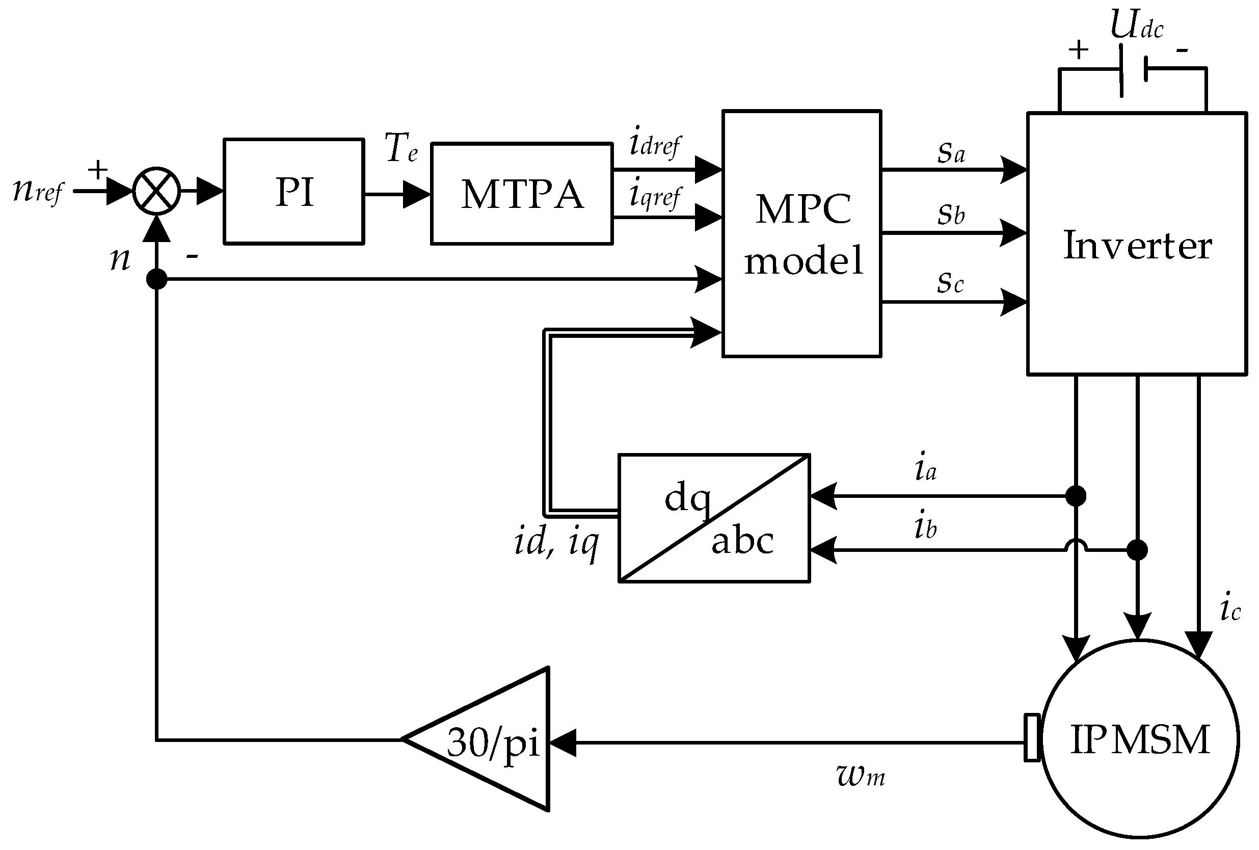
The block diagram of the FOC scheme of IPMSM using proposed FCS-MPC is shown in
Figure 1. As shown in proposed method, the speed loop is controlled by a traditional PI controller, and accurate tracking of stator current is accomplished by FCS-MPC controller.
Where, ia, ib, and ic are a-phase, b-phase, and c-phase stator currents, respectively, and the state definitions for each arm are as follows. Sa, Sb, and Sc are the switching states of the three bridge arms, respectively. When the value of Sa, Sb, or Sc is equal to 1, the corresponding bridge arm is in the open state. Conversely, the bridge arm is in the close state when the value of Sa, Sb, or Sc is equal to 0.
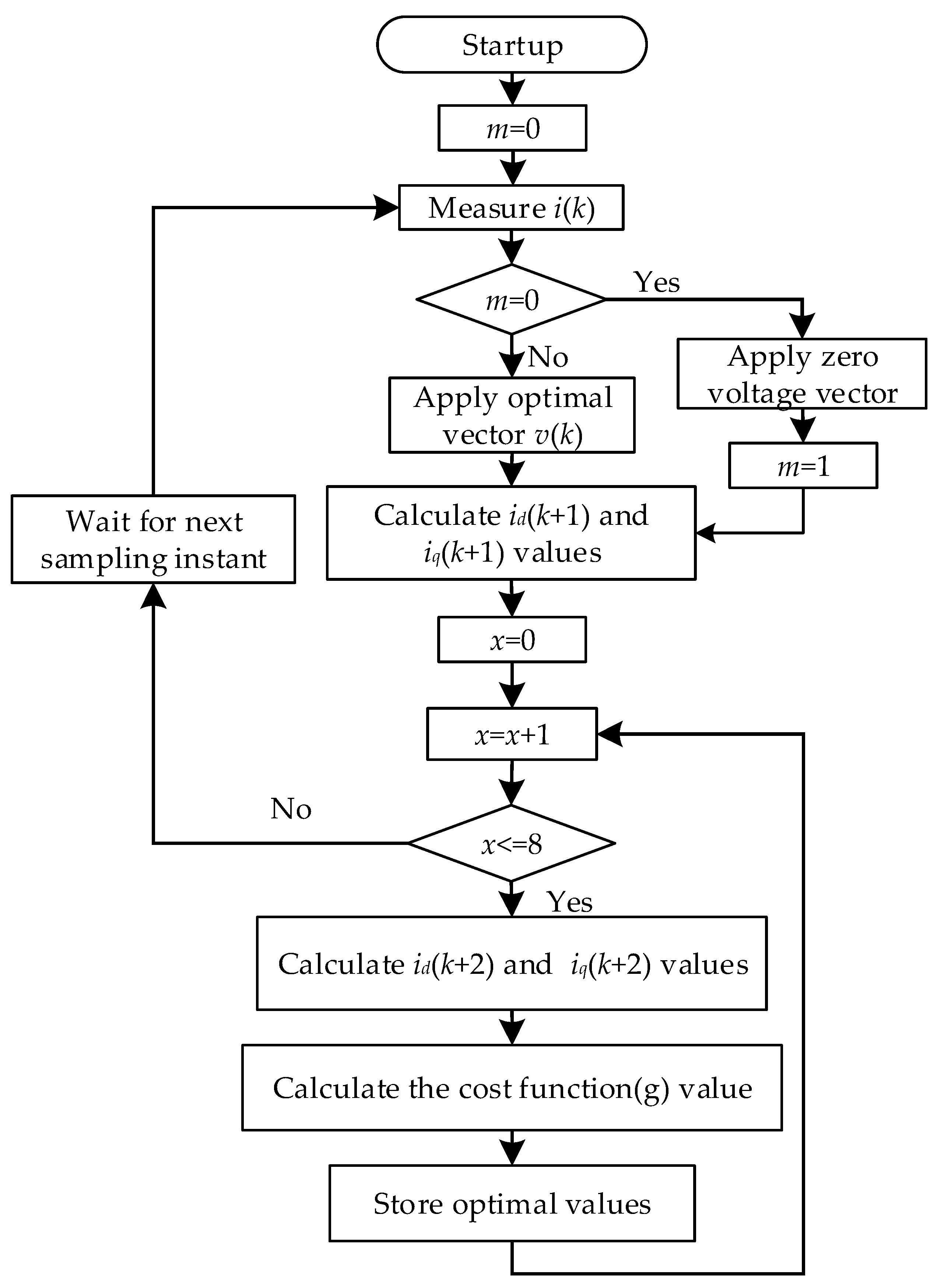
When control schemes based on FCS-MPC are adopted, a large number of calculations are required, introducing a considerable time delay in the actuation. This delay will deteriorate the performance of the system if not considered in the design of the controller. A simple solution to compensate this delay is to take into account of the calculation time and apply the selected switching state after the next sampling instant. The model predictive control algorithm with delay compensation can be represented as the flowchart presented in
Figure 2.
In
Figure 2,
m is the intermediate variable, which is set to judge whether the system is sampling for the first time. When the system is initialized and started,
m = 0 is set. At this time, the system has not calculated the optimal voltage vector; zero voltage vector is applied, and
m = 1 is set. During the operation of the system,
m = 1 is kept, and the optimal voltage vector provided by the predictive controller can be applied. Moreover,
x, from 1 to 8, represents eight switch states of two-level inverter, namely, 000, 001, 010, 011, 100, 101, 110, and 111. When the upper bridge arm is turned on and the lower bridge arm is turned off, it is expressed as 1. Otherwise, when the upper bridge arm is turned off and the lower bridge arm is turned on, it is expressed as 0.
The output voltages of the inverter, in PWM forms, cannot be measured directly. For the IPMSM vector control system based on traditional PI controller, the outputs of the PI controllers in current loop are usually approximated to the actual input voltages ud and uq of IPMSM.
However, the traditional current PI controller is alternated by FCS-MPC controller in IPMSM predictive control system. In order to obtain the effective values of
ud and
uq, it can be reconstructed by DC bus voltage
Udc, inverter switching state, and rotor position electrical angle
θ. The equation is shown in Equation (9):
where
UAN,
UBN, and
UCN are the phase-to-neutral voltage of the inverter.
Udc is DC bus voltage, and
θ is the rotor position electrical angle.
However, the values of ud and uq, obtained from Equation (7), are in the PWM forms, which contain large numbers of high-order harmonics and cannot be used in parameter identification algorithm. An effective solution to obtain the effective values of ud and uq of the inverter is to make the voltages pass through low-pass filters.
3. FCS-MPC of IPMSM Based on Parameter Identification
3.1. Online Parameter Identification Strategy
In order to identify the d-axis inductance, q-axis inductance and rotor permanent magnet flux linkage of IPMSM simultaneously, the rank of the identification coefficient matrix of motor parameters must be greater than or equal to three. However, the maximum rank of the coefficient matrix of the steady-state operation of the motor is two. Two methods are usually adopted to solve the under-rank problem. The first is to obtain the multi-group operation state of the motor by injecting current signal, thereby increasing the rank of identification equations. The second is to divide the parameter identification system into different parts and identify them alternately. However, the first method has some limitations; a fixed current vector will be generated in the motor, which will cause torque ripple, affecting the control accuracy and running quality of the system. The identification accuracy is also heavily dependent on the quality of the injected current signal.
With the MTPA control method, when the motor is running in steady state, Equation (1) is rewritten as the following matrix form:
Φ is defined as the coefficient matrix of motor parameter identification.
The first and third columns of matrix Φ are linearly correlated. Therefore, it is impossible to identify the d-q axis inductances and permanent magnet flux linkage of IPMSM simultaneously. In order to solve the above problem, the parameters of the motor were estimated by the step-by-step identification strategy in this paper.
Through the above analysis, the IPMSM motor parameters can be identified by step-by-step identification strategy proposed in this paper. Considering the under-rank problem of the motor parameter identification matrix, the motor parameters are usually divided into several groups depending on the motor parameters’ changing speed, in which a part of the motor parameters are set to known values, and then, the parameter identification algorithm is used to estimate the remaining parameters. Based on the identification result, the original set parameters values are identified in the next step, so that all parameters of the motor can be identified and cyclically updated by the method proposed in this paper.
3.2. Adaline Neural Network Identification Method
In this paper, the Adaline neural network algorithm is used to identify the motor parameters. It is a linearly adjustable network, which is very similar to the single layer perceptron [
38], except that the functions of creating neural networks are different. It has the characteristics that the network weight and threshold can be directly obtained by using the design function without training, and the output of the network layer can take any value, overcoming disadvantages of the output of the perceptron neural network which can only be 0 or 1. Therefore, it is suitable for the fields of adaptive filtering, prediction and model recognition in signal processing. By observing its excitation function and weight function, we can find that its expression only contains simple addition, subtraction, and multiplication calculations and does not contain matrix calculation or division calculation. The calculation amount is small, and there is only one adjustable parameter (step size), which makes it easy to adjust compared with nonlinear neural network [
32,
33]. Combining the above advantages, the Adaline neural network identification method is selected in this paper.
The principle of parameter identification of Adaline neural network is as follows:
First, the network structure matching the control system is selected, and the input variables are taken into the neural network identifier. Then, according to the output error between the identification system output and the network output, combined with the weight convergence algorithm, the network weight correction is performed to realize the online parameter identification.
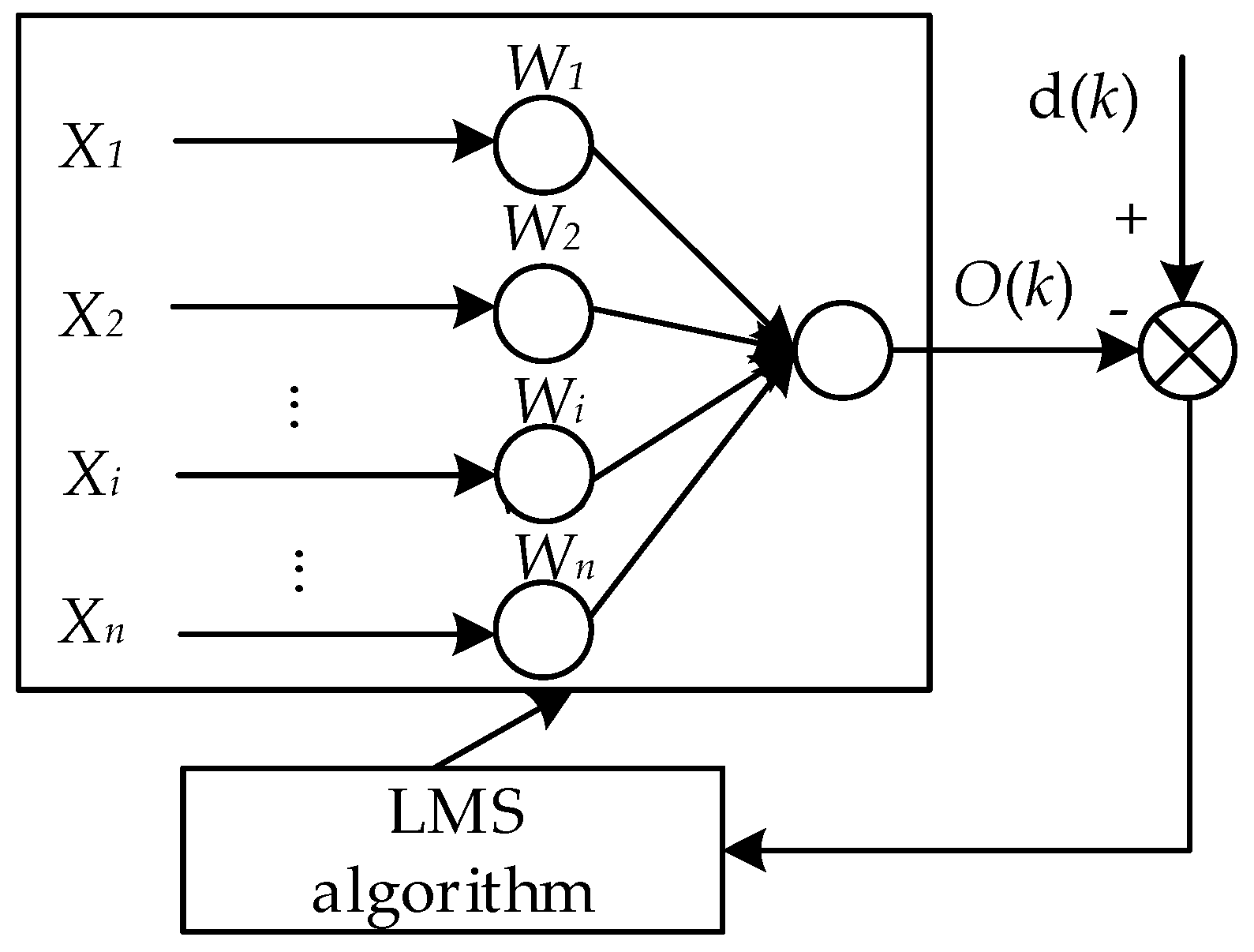
The structure diagram of Adaline neural network is as follows in
Figure 3:
Its excitation function is:
where
Wi is the weight of the neural network,
Xi is the network input signal, and
O(Wi, Xi) is the output of excitation function of the network.
The weight adjustment algorithm of the network when the least mean square (LMS) algorithm is used is:
where
d(
k) is the network target output,
η is the weight adjustment size, and
ε(
k) is the error between the neural network output and the target output.
When the motor parameters are estimated by the Adaline neural network algorithm,
Ld,
Lq, and
Ψf are regarded as the weights of the network, and the values of the motor parameters can be obtained by weight calculation. In order to ensure the convergence of the algorithm,
η in Equation (13) needs to satisfy the following relationship [
31]:
In the above algorithm, the real gradient is replaced by the estimated gradient. The correlation matrix and the inverse matrix are not needed, which makes the computation speed faster. When the convergence factor is selected properly, the stability and rapidity of the identification system can be guaranteed simultaneously.
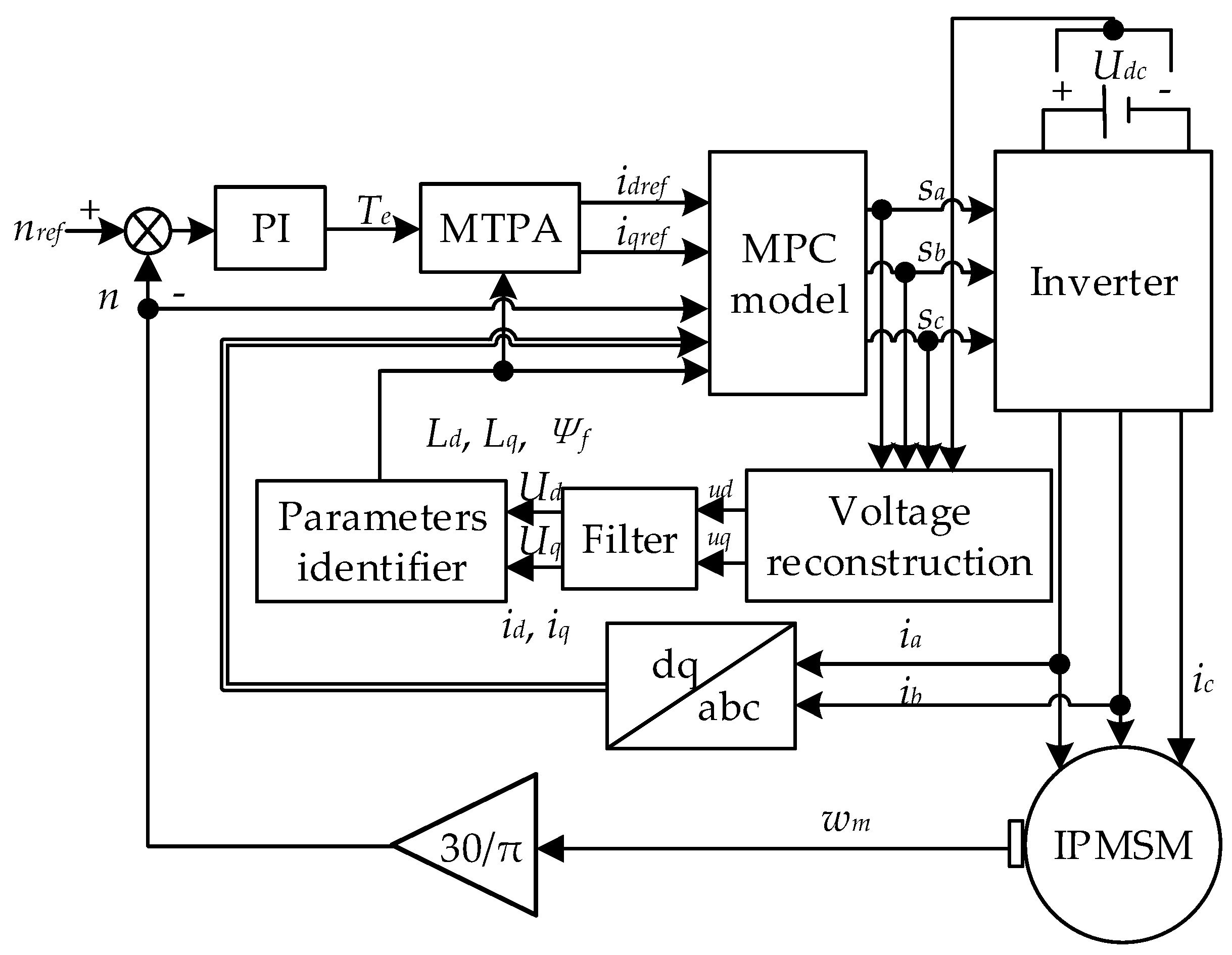
In this paper, an on-line parameter identification method of IPMSM based on Adaline neural network is proposed. The motor parameters are identified in four steps. First, when the motor rotor is in a static state, the stator resistance is measured by injecting d-axis current. Second, when the motor is started, the resistance value in the voltage equation is set to static measurement value, and the q-axis inductance is estimated. Third, the permanent magnet flux linkage and the d-axis inductance are identified. Finally, the motor parameters are cyclically updated. It is assumed that the stator resistance remains constant. According to the motor torque equation, d-axis inductance, q-axis inductance, and rotor flux linkage of IPMSM can be obtained, respectively. The identification equations are as follows:
where,
Ud and
Uq are the effective values of ud and uq.
The model predictive control block diagram of IPMSM based on parameter identification with Adaline neural network is shown in
Figure 4.
4. Experimental Results Analysis
In order to verify the effectiveness of the model predictive control algorithm based on parameter identification mentioned in this paper, an experimental platform is built based on TI 2812 DSP chip (Texas Instruments, Dallas, USA) for experiment. The parameters of the IPMSM motor are listed in
Table 1. In the practical experiment, the crude estimation values are defined as the true parameters of IPMSM (
Ld0,
Lq0, and
Ψf0), which are utilized for experiments under parameter mismatch conditions.
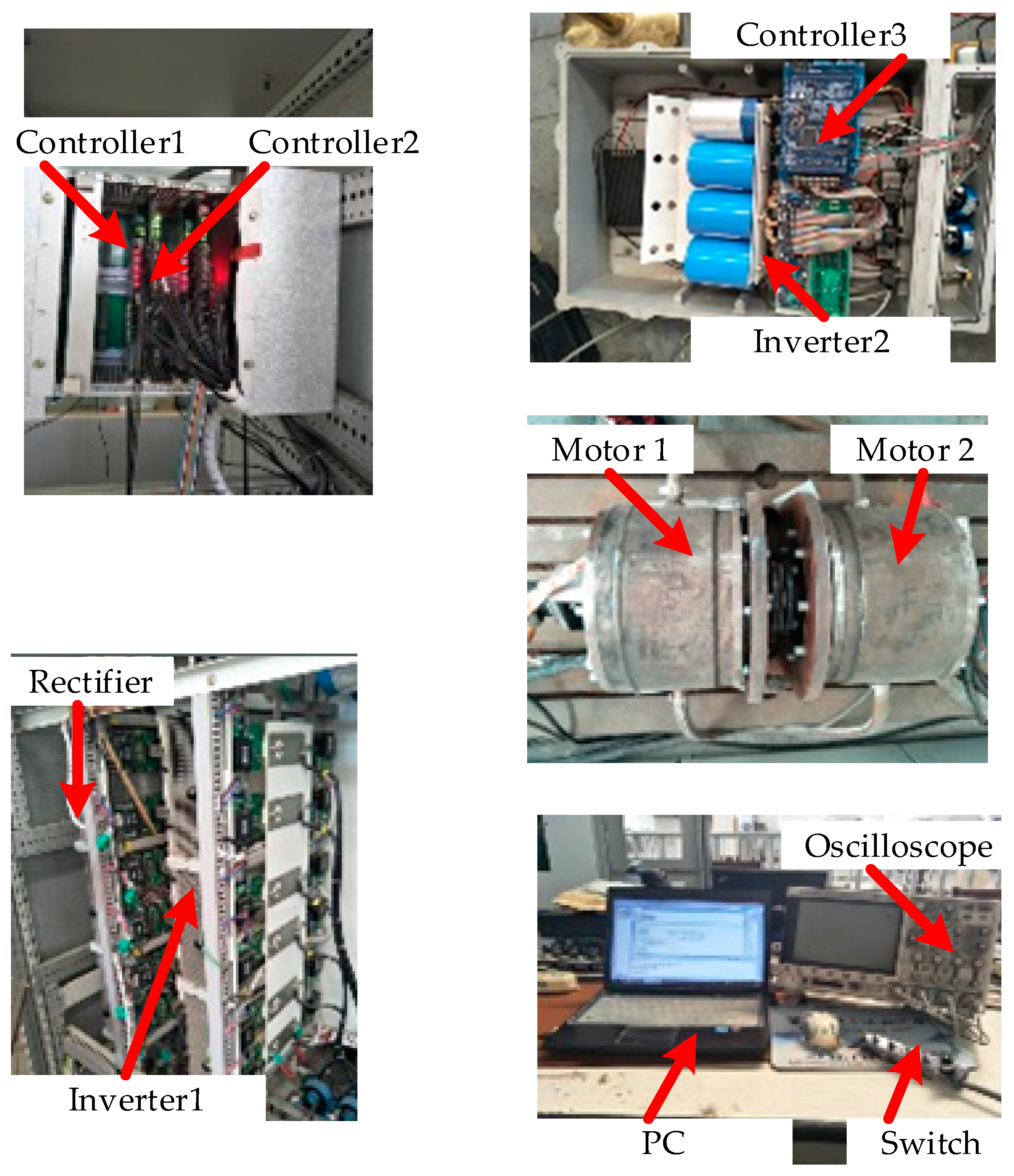
The experimental platform is constructed by TI processor, which is mainly composed of two IPMSMs, one rectifier, two inverters, and three controllers. The experimental platform is shown in
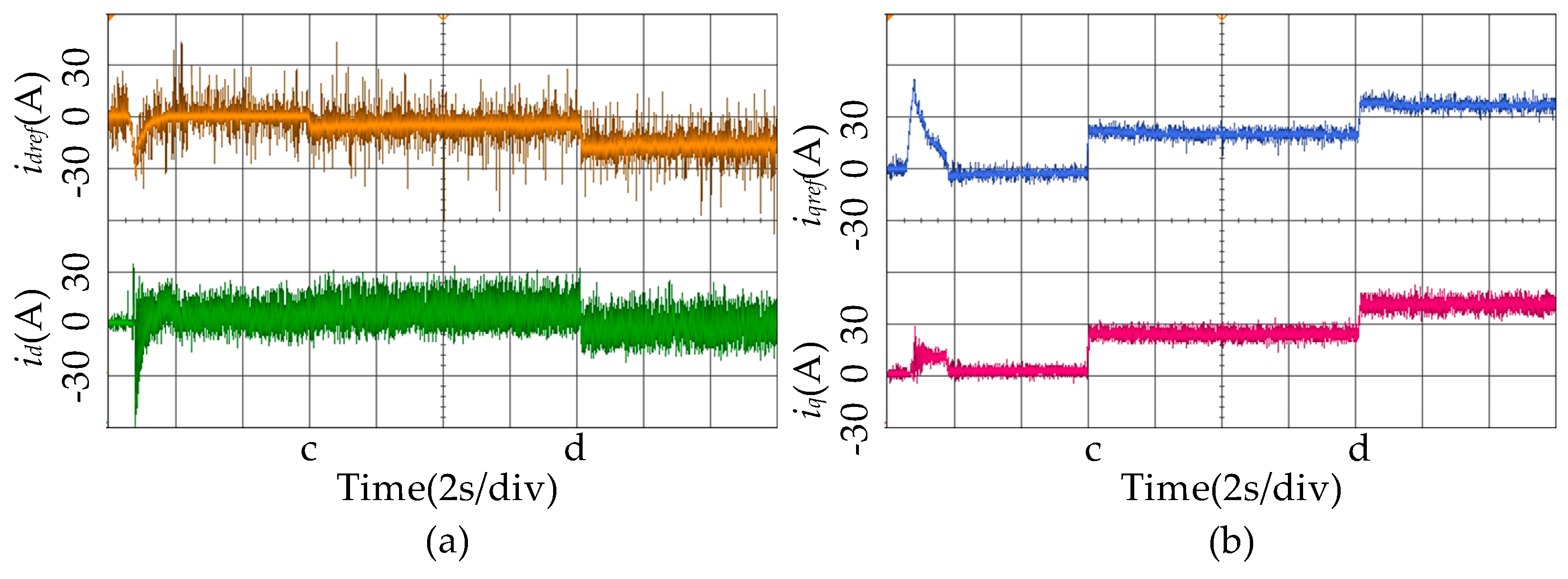
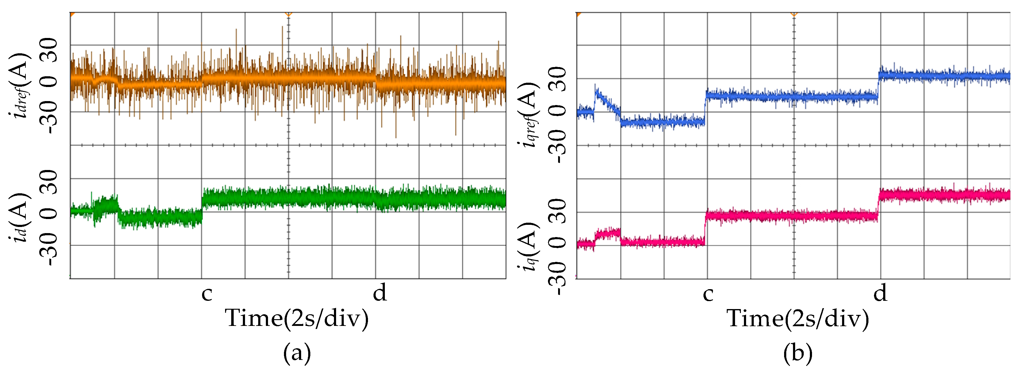
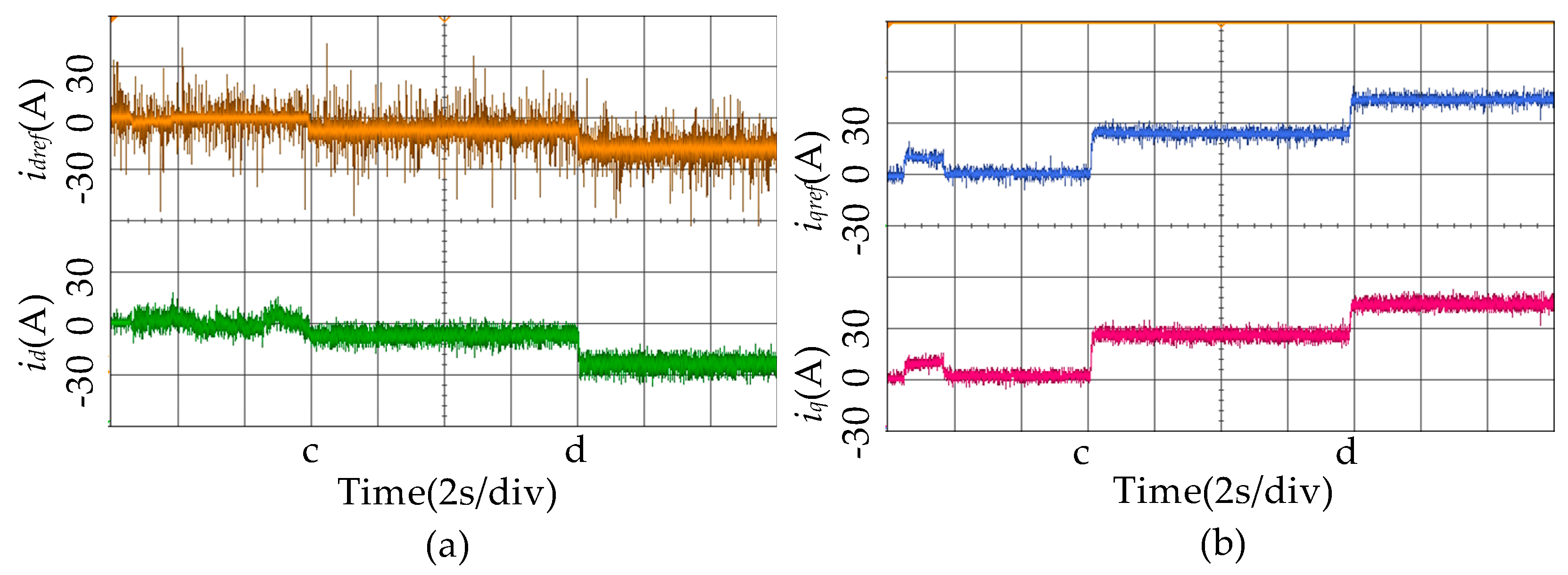
Figure 5. Sampling frequency of the control system is set to 10 kHz, and the speed reference is 900 rpm. A rotary decoder is employed to obtain the position and speed of the motor rotor. In order to verify the effectiveness of the method at variable load, the load torque of 40 Nm and 30 Nm are suddenly added at times c and d.
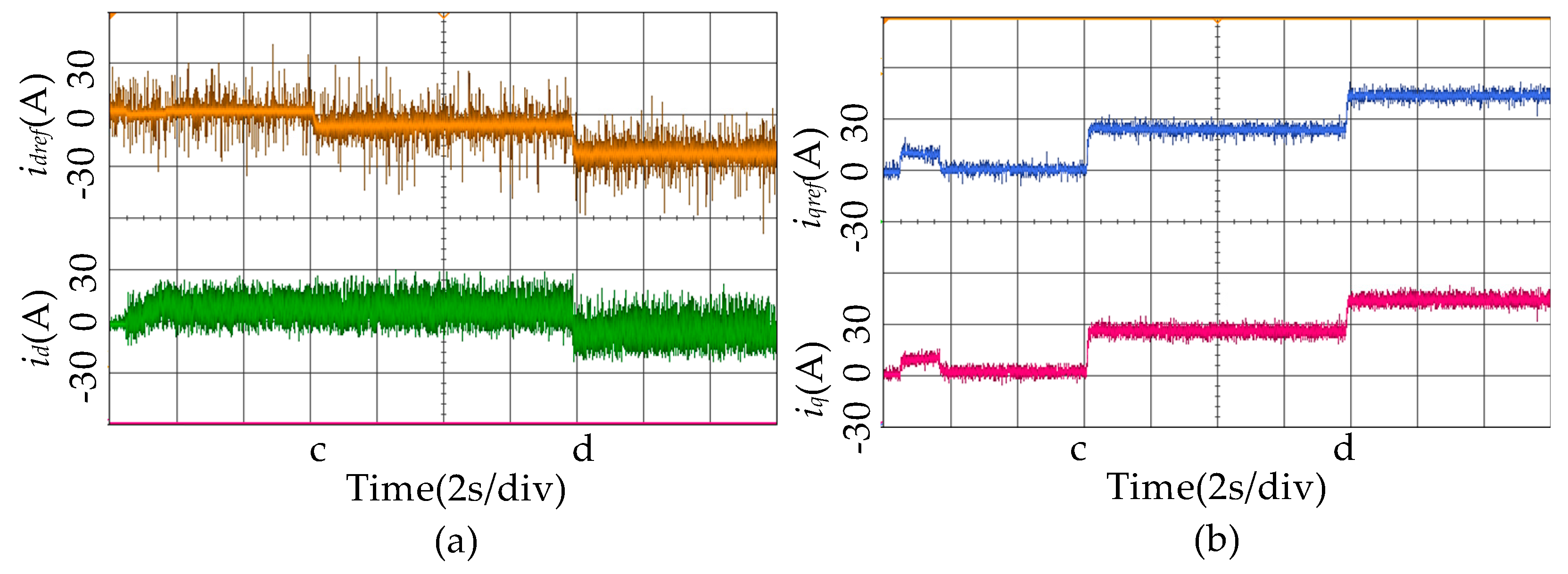
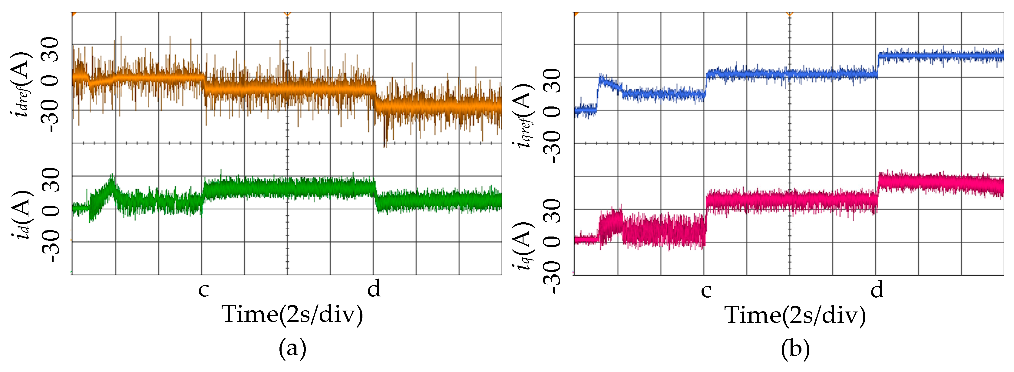
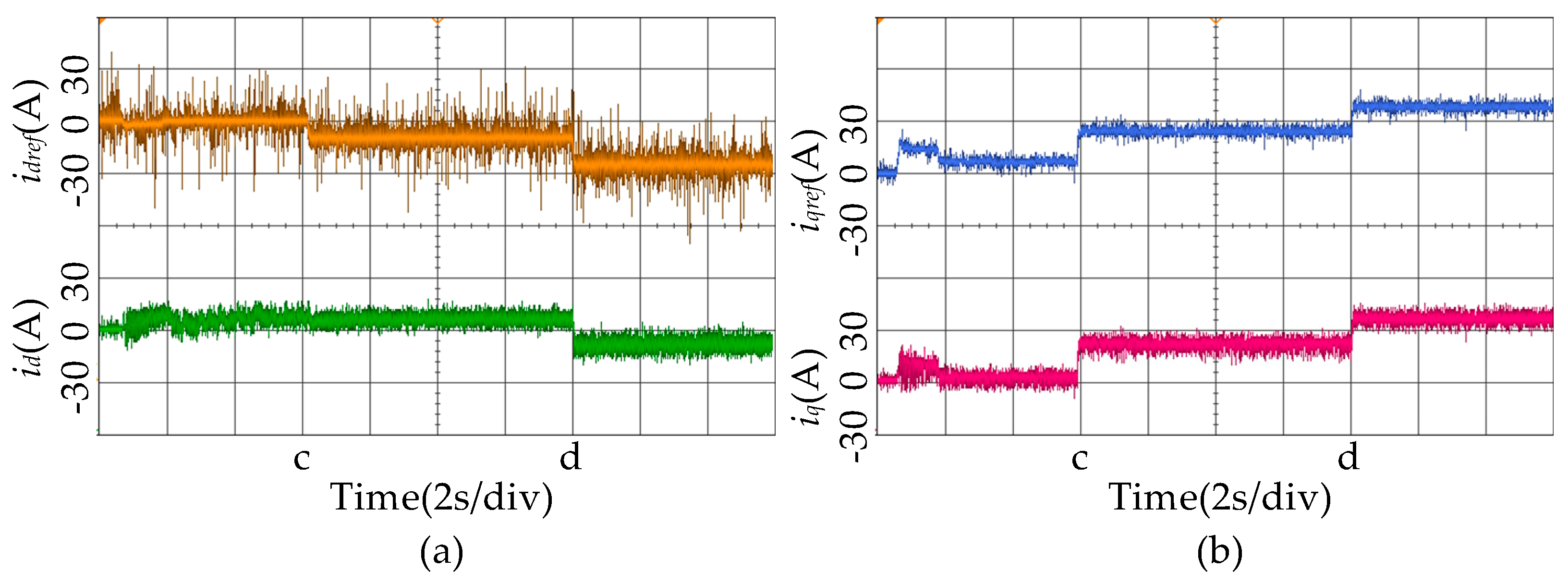
The experiment was conducted in three parts. The experimental results of current references and current responses with different parameter mismatch are shown in
Figure 6,
Figure 7,
Figure 8,
Figure 9,
Figure 10 and
Figure 11. The orange and blue lines represent the d-axis current and q-axis current reference values respectively. The green line and the red line represent the current response values of d-axis and q-axis respectively. As can be seen from
Figure 6,
Figure 7,
Figure 8,
Figure 9,
Figure 10 and
Figure 11, when the parameters are mismatched, the error between the predictive current and the current reference value increases, and the control effect is seriously disturbed. The reason why the control effect is disturbed is that the control performance of IPMSM controlled by FCS-MPC is heavily dependent on the motor parameters. When the motor parameters do not match the motor parameters in the controller, the deviation between the reference current and the response current will occur. More importantly, the parameter mismatch causes significant response current fluctuations, which will have a bad impact on the control performance of the control system.
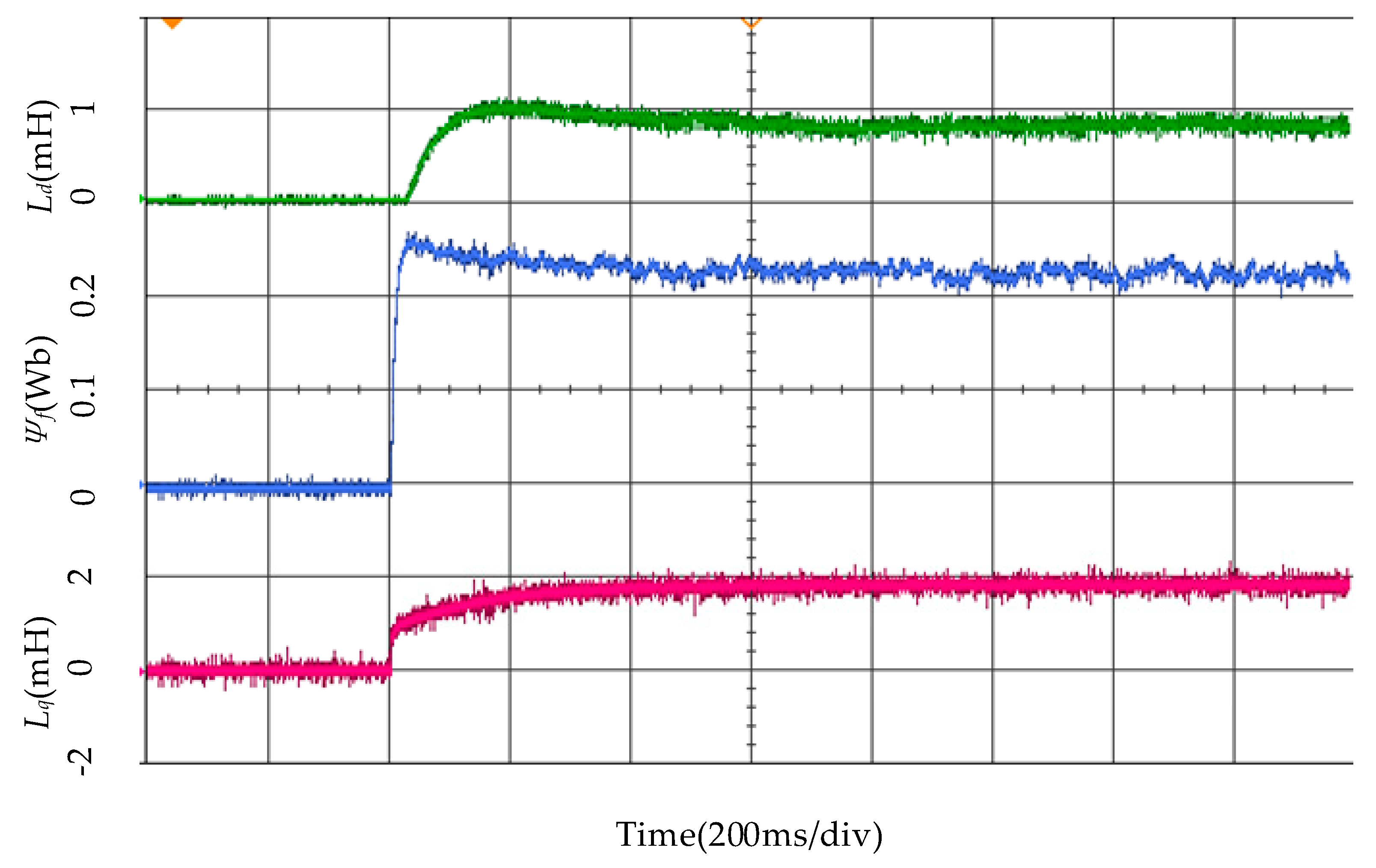
Afterwards, the result of the IPMSM parameters identification based on the FCS-MPC and Adaline neural network algorithm was verified.
Figure 12 shows the identification result of the d-q axis inductances and the rotor permanent magnet flux, where the d-axis inductance is represented by orange line, the q-axis inductance is represented by red line, and the rotor permanent magnet flux linkage is represented by blue line. It can be seen from the figure that the motor parameters can be quickly and accurately estimated in real time by the algorithm proposed in this paper so that the identification values can be applied to the FCS-MPC controller.
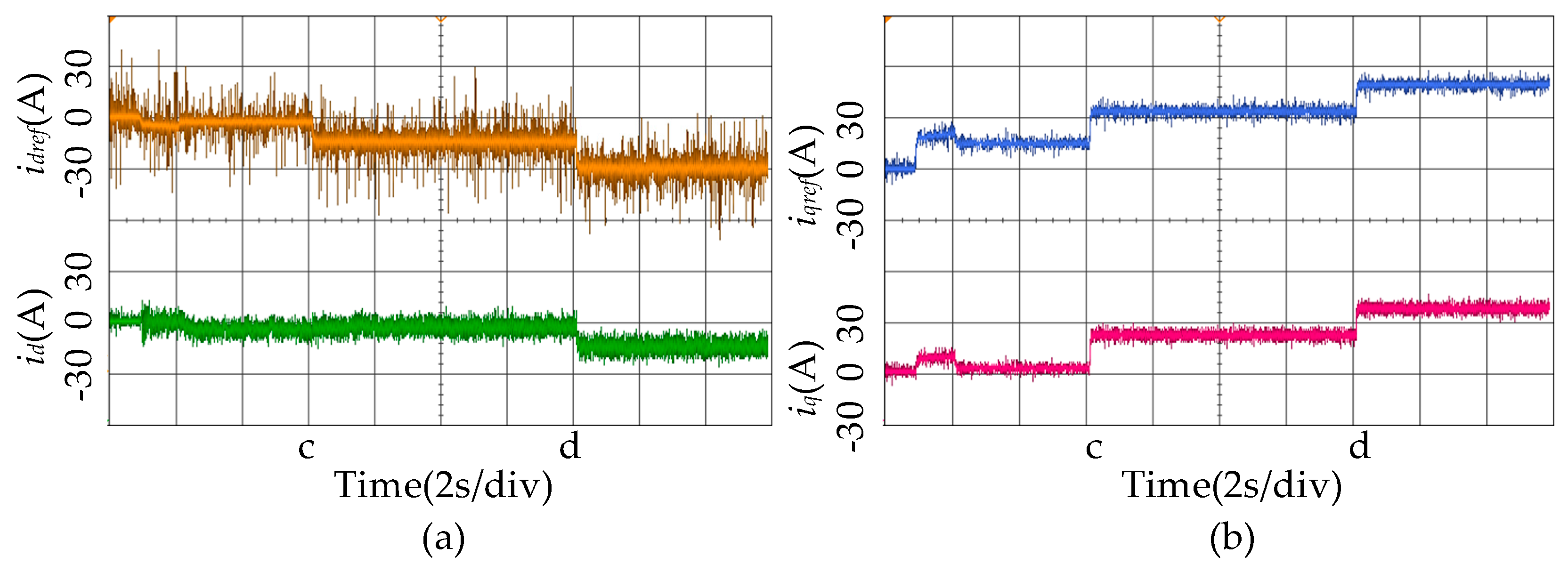
Finally, the experimental results of current references and current responses with MPC based on Adaline parameter identification method are shown in
Figure 13. The orange and blue lines represent the d-axis current and q-axis current reference values, respectively. The green line and the red line represent the current response values of d-axis and q-axis, respectively. Comparing with the parameters mismatch condition, it can be found that in this case the d-q axis, current responses can track the current references better and significantly reduce the errors between them. The reason is that during the operation of the motor, the motor parameters can be estimated effectively, and the controller parameters can be adjusted as well, which can effectively improve the current control effect even under the changing load operating state.
From the analysis of the experimental waveform, it can be known that the disturbance of motor parameters can deteriorate the performance of IPMSM operating based on FCS-MPC control strategy with MTPA method. The accuracy of steady-state tracking of the d-q axis currents are affected by the values of IPMSM parameters. By adopting the proposed optimal MPC method based on Adaline neural network algorithm in this paper, the d-q axis current static error can be eliminated in the presence of parameters disturbance.


