Abstract
Gears are important components of the transmission system. Tooth wear and bearing clearance are significant factors affecting the dynamics of the gear system. In order to reveal the effects of gradual wears and bearing clearance on the gear system dynamics, a six-degrees-of-freedom bending-torsion coupled model of gear-rotor-bearing which considers surface wear, bearing clearance and backlash is established. The Rung-Kutta method is used to solve the nonlinear dynamic system, and the dynamic responses of the system are obtained. The results show that the time-varying mesh stiffness decreases with the tooth surface from the unworn phase to severe wear phase. At the same time, the change of the mesh stiffness in the double-tooth mesh area and single-tooth area are different. Moreover, the amplitude of the X-displacement, Y-displacement and relative gear mesh displacement will be enlarged slightly with the increase of wear depth or bearing clearance. By analyzing variation tendency in the frequency domain, the different order harmonics show the different change characteristic with the variation of the wear phases or bearing clearances. This study provides a theoretical basis for improving the transmission performance and the selection of the bearing clearances in the gear system.
1. Introduction
Geared rotor bearing systems are commonly employed as power transmission mechanisms, and gear system dynamics has received significant attention in recent years. The multi-clearances, including bearing clearance and backlash, is an important factor affecting the dynamics of the gear system. In the process of gear meshing, due to the need for lubrication and manufacture errors, there will be a backlash between the conjugate teeth pair. The presence of the backlash causes an impact between the conjugate teeth pair, which affects the stability of the gear transmission [1]. The bearing clearance affects the number of rolling elements which can bear the load. Meanwhile, due to the presence of the bearing clearance, the gear center distance and pressure angle will change accordingly. Thus, the bearing clearance has an important impact on the dynamic characteristics of the system. In addition, tooth wear is inevitable, resulting in the tooth profile deviating from the ideal tooth profile. The gradual wears affect the backlash and the meshing stiffness [2,3,4], and also affect the friction between conjugate teeth pair. Gear tooth wear occurs over relatively long periods of service, severe wear can lead to an occurrence of other types of gear failures such as pitting and broken teeth [5]. It can be seen that consideration of these factors, which incorporate tooth wear and multi-clearances, has important implications for the dynamics of the gear system.
In the process of gear system dynamics research, scholars have gradually noticed the significant influence of backlash and bearing clearance on system dynamics. Researchers have made a lot of meaningful achievements in the study of system dynamics of bearing clearance and backlash from theory and experiment. The backlash and the time-varying stiffness gear model is proposed by Kahraman [6], and then the dynamic response characteristics of the gear system are analyzed. Chen et al. [7] derived the connection between the gear central distance error and backlash, and defined the dynamic backlash. After that, they established a multi-degree of freedom gear system model, and the influence of dynamic backlash on the system was studied. In order to study the influence of backlash and time-varying mesh stiffness on the dynamics of gear system, a set of test equipment with adjustable backlash was established by Cui et al. [8]. The gear system model is improved by Gou et al. [9], and the influence of the backlash, bearing clearance, flash temperature and mesh stiffness on the nonlinear dynamics is obtained. Xu et al. [10] explored the influence of the backlash and bearing clearance on the characteristics of the gear transmission system by establishing an eight-degrees-of-freedom dynamic model.
Tooth wear changes the profile of gears, which will inevitably affect the system dynamics, Zhang et al. [11] restructured the wear tooth profile, and obtained the dynamic meshing force, the result indicated tooth wear enlarge the peak of dynamic meshing force. The elastic dynamics model of gear teeth with two degrees of freedom was established by Wojnarowski et al. [12]. Later, they analyzed and studied the effects of deformation and wear on the dynamics of spur gears. Ding et al. [13] established a dynamic model considering the factors such as tooth surface wear and comprehensive errors, and studied the influence of surface wear on the dynamics of the gear system. For the ideal involute spur gear, Feng et al. [14] studied the calculation method of the gear meshing stiffness when the tooth surface is worn. Wang et al. [15] used the Archard model and Weber-Banaschek model to calculate the cumulative wear of the tooth surface and the time-varying meshing stiffness of the wear gear pair, and they proved that the gear system has complex dynamic characteristics due to the surface wear. Liu et al. [16] replaced the effects of wear with a modulated mesh impact and introduced them into the system dynamics model to derive the effect of wear on the dynamics of the gear system.
Scholars have done a lot of research on the dynamics of gear systems with factors such as multi-clearances and wear, and have achieved many meaningful results. During the gear transmission process, the tooth wear increases continuously. The wear affects mesh stiffness continuously, thereby changing the dynamic characteristics of the gear system. The current research has not comprehensively considered the effects of wear and multi-clearances on the dynamics of the gear system. At the same time, there is little research on the influence of bearing clearance on gear center distance. In view of this, firstly, the dynamic model of six-degrees-of-freedom single stage spur gear transmission system considering wear and multi-clearances is established in this paper. Then, the time-varying mesh stiffness corresponding to different wear depths are obtained, and thus the tooth wear is introduced into the system dynamics model. Therefore, a more realistic system model is obtained. Based on this model, the effects of gradual wears and bearing clearance on the dynamics of the gear system are analyzed by numerical simulation.
2. Model Description
2.1. Gear Dynamic Model
Figure 1 shows the six-degrees-of-freedom bending-torsion coupled model of the gear-rotor-bearing. The specific vibration form of the drive shaft is not considered. yp, xp and θp represent the vertical displacement, transverse displacement and torsional displacement of the driving gear, yg, xg and θg represent the vertical displacement, transverse displacement and torsional displacement of the driven gear. The subscripts p and g represent driving gear and driven gear, respectively. Other parameters are listed in Table 1. The gear mesh is described by a non-linear displacement function and viscous damping. The friction force at the mesh point is assumed to be negligible. Further, it is assumed that input torque and output torque are constant.
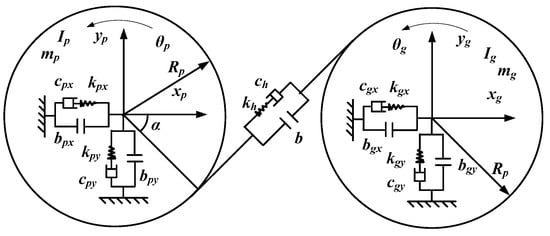
Figure 1.
Dynamic model of gear-rotor-rolling bearing transmission system.

Table 1.
The parameters of the dynamic model.
2.2. Tooth Wear Model
In the process of gear meshing, the wear of the tooth surface makes the tooth profile deviate from the original tooth profile and causes the impact. As mentioned before, gear wear causes the change of gear mesh stiffness, and affects the dynamic characteristics of the gear system.
According to the literature [15] and Equation (1), the wear depth at each point of the gear tooth profile can be obtained.
where μ is the gear slide coefficient; Ih is the coefficient of wear characteristic, E1 and E2 are modulus of elasticity of driving gear and driven gear. ν1 and ν2 are the Poisson ratio of the driving gear and driven gear, m is the gear module, α is the pressure angle in pitch circle, Tp is the input torque, ψ is the width coefficient, t is the gear working time, n is the rotation speed, the parameters of gear and bearing are listed in Table 2.

Table 2.
Parameters of gear and bearing.
Effect of Wear on Mesh Stiffness
The contact ratio of the gear is greater than 1; therefore, there are different logarithmic teeth alternately meshing during the gear meshing process, resulting in periodic variation in tooth meshing stiffness according to the Weber stiffness model, as shown in Figure 2. Assume that the gear tooth is the cantilever beam, the effective length of the cantilever beam is Le, the gear tooth is divided into a series of infinitesimal elements along the X axis. The infinitesimal element is represented by i.
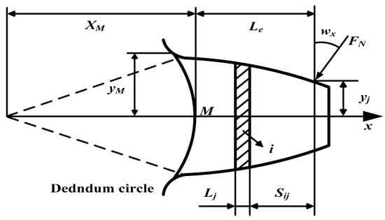
Figure 2.
Mesh stiffness model.
The gear deformation is divided into three parts: (a): bending deformation and shear deformation of gear tooth; (b): deformation produced by the tooth root (c): local deformation caused by contact stress.
δ1 is the tooth deformation, it can be obtained by Equation (2).
δ2 is deformation produced by the tooth root, it can be obtained by Equation (3).
δ3 is the local deformation caused by contact stress, it can be obtained by Equation (5).
The meshing stiffness kh can be obtained by Equation (6).
The is the deformation of the driving gear and is the deformation of the driven gear.
Here, FN is the load. The Lj is the thickness of infinitesimal element, ωx is the load angle, and Ai is the area of the infinitesimal element, Sij is the distance from the infinitesimal element to the loading points. More detailed parameters are given in the reference [17].
The gradual wear causes the change of the involute gear tooth profile, introduce the wear depth on the tooth surface into Equations (2), (3) and (5). Finally, the gear time-varying meshing stiffness corresponding to different wear depths can be obtained by the Equation (6).
2.3. Bearing Clearance Model
2.3.1. Bearing Clearance Function
The bearing clearance is the gap between the bearing rolling element with the inner and outer ring housing of the bearing. The size of the bearing clearance affects the number of rolling elements which bear the load and will have a great influence on the response of the whole gear system.
According to Figure 3, the bearing clearance is processed into a non-linear displacement function as follows.
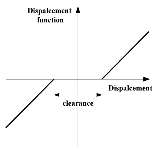
Figure 3.
Non-linear bearing clearance function.
2.3.2. Influence of Bearing Clearance on Center Distance
Due to the presence of the bearing radial clearance, radial runout occurs during the operation of the gear system, which causes the change of the center distance. Thus, it is necessary to establish the relationship between the bearing clearance and the center distance. Figure 4 is the model of the bearing clearance and center distance.
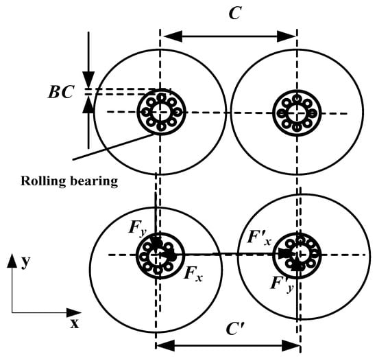
Figure 4.
The model of the bearing clearance and center distance.
BC indicates bearing clearance. C is the theoretical center distance and C′ is the center distance which considering the influence of the bearing clearance. Fx and Fy represent the contact force in X-direction and Y-direction on driving gear, respectively. F′x and F′y represent the contact force in X-direction and Y-direction on driven gear, respectively.
We can obtain the relationship between bearing clearance and center distance as follows:
where kb is the rolling bearing stiffness, and it is assumed to be constant.
2.3.3. The Model of the Center Distance and Backlash
The backlash is used to describe the gap of the teeth along the mesh line. Theoretically, the backlash is 0. However, due to the need of lubrication and manufacture errors, there will be a backlash between the conjugate teeth pair, we define this gap as the initial backlash b0. Actually, the change in the gear center distance will cause a corresponding change in the backlash. As we all know, the backlash is a nonlinear factor affecting the dynamic behavior of the system. So, the relationship between the center distance and the backlash is particularly important. Figure 5 is the model of the center distance and backlash. The P is the mesh point. R1 and R2 are pitch circle.
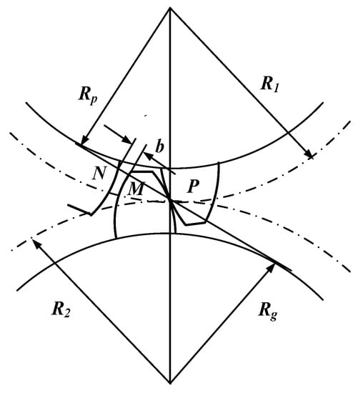
Figure 5.
The model of the center distance and backlash.
In the process of gear mesh, due to presence of the initial backlash b0, the point N does not coincide with the point M. According to the geometric relationship, the actual backlash can be expressed as:
A formula was derived to calculate the backlash b:
where sp and sg are pitch tooth thickness of driving and driven gear. α is the actual pressure angle.
According to the Equations (13) and (14), the relationship between the backlash and the actual center distance can be expressed as:
2.4. Equations of Motion
According to the gear dynamic model in the Section 2.1, we can obtain the equation of motion as follows:
The static transfer error is not considered, so the relative gear mesh displacement can be defined as:
where TP/Tg is the input/ output torque of the gear dynamic system, Fm is the dynamic gear force, it can be obtained by Equation (19)
f(δ) is the backlash function of the displacement, it can be rewritten as:
3. Numerical Simulation and Discussion
3.1. Influence of Gradual Wears on System Dynamics
This section is to investigate the influence of gradual wears on gear dynamics. The following sections will detail the response of the gear system under the effect of gradual wears.
3.1.1. Gear Mesh Stiffness Under Different Wear Phases
Figure 6 shows the time-varying mesh stiffness curves under the unworn, mild wear phase and severe wear phase, respectively.
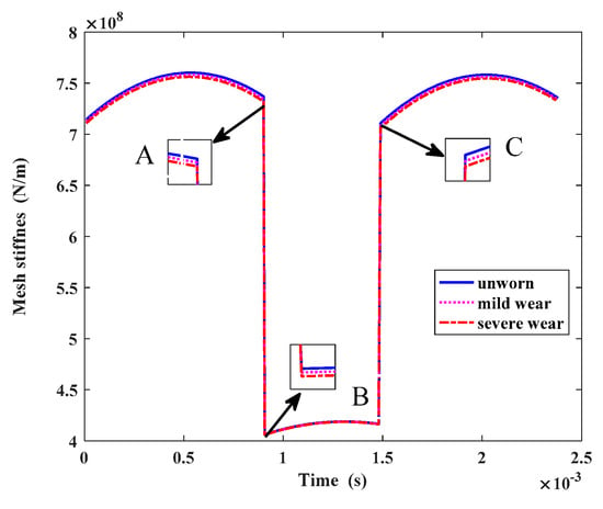
Figure 6.
Mesh stiffness at different wear depths.
The horizontal axis represents time and the vertical axis represents the mesh stiffness value. Figure 6 shows the meshing stiffness of gears in a cycle under different bearing clearances. In Figure 6, A and C represent the double tooth mesh area respectively, and B represents the single tooth mesh area. Overall, the increase of the tooth surface wear depth reduces the mesh stiffness. At the beginning of the A-segment (double-tooth mesh area near the tooth tip), the change of the tooth mesh stiffness is most obvious under the different wear depths. From the A-segment to the B-segment (single-tooth mesh area near the pitch point), the change of tooth mesh stiffness gradually becomes weak under the different wear depths. From the B-segment to the C-segment (double-tooth mesh area near the tooth root), the change of the tooth mesh stiffness gradually becomes apparent under the different wear depths, which is consistent with the reference [18]. The reason for this may be because the wear depth of the single-tooth mesh area is tiny during the gear mesh process, which is much smaller than the wear depth of the double-tooth mesh area, so the stiffness does not change significantly in the single-tooth mesh area.
3.1.2. Translational Displacement
Figure 7a depicts the Y-displacement under different wear phases. The amplitude of the displacement will be enlarged slightly with the increase of wear depth which is mainly caused by the deterioration of gear surface. There is a change in Y-displacement induced by the wear phases. The change in the Y-displacement is shown in Figure 7b. To investigate the variation of the Y-displacement, the first four harmonics of the meshing frequency are illustrated in Figure 8, and fm = 600 Hz (below is the same). As can be seen, the first order, second order and fourth order harmonics are enlarged with the increase of the wear depth and change linearly. However, the third harmonic is descending.
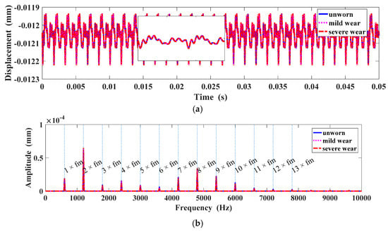
Figure 7.
Displacement in the Y direction under different wear phases: (a) Y-Displacement; (b) dis-placement spectrum in the Y direction.
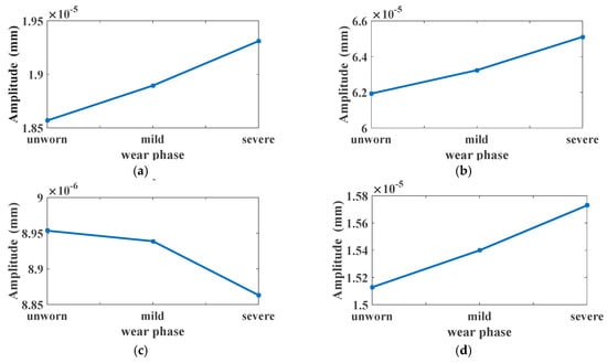
Figure 8.
Harmonics of mesh frequency in Y-displacement spectrum under different wear phases: (a) 1 × fm at 40 Nm; (b) 2 × fm at 40 Nm; (c) 3 × fm at 40 Nm; (d) 4 × fm at 40 Nm.
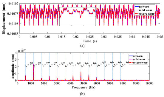
Figure 9.
Displacement in the X direction under different wear phases: (a) X-Displacement; (b) dis-placement spectrum in the X direction.


Figure 10.
Harmonics of mesh frequency in the X-displacement spectrum under different wear phases: (a) 1 × fm at 40 Nm; (b) 2 × fm at 40 Nm; (c) 3 × fm at 40 Nm; (d) 4 × fm at 40 Nm.
3.1.3. Relative Displacement
Figure 11a depicted the relative displacement under different wear phases. The amplitude of the relative displacement will be enlarged slightly with the increase of wear depth. The spectrum of relative displacement is shown in Figure 11b. To investigate the variation of the relative displacement, the first four harmonics of the meshing frequency are illustrated in Figure 12. As can be seen, the first order, second order and fourth order harmonics are enlarged with the increase of the wear depth. However, the third harmonic is descending for the wear phases from unworn to mild wear, and then increasing for the wear phases from mild wear to severe wear.
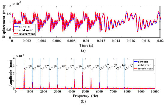
Figure 11.
Relative displacement under different wear phases: (a) Relative displacement; (b) Spectrum of relative displacement.


Figure 12.
Harmonics of relative displacement spectrum under different wear phases: (a) 1 × fm at 40 Nm; (b) 2 × fm at 40 Nm; (c) 3 × fm at 40 Nm; (d) 4 × fm at 40 Nm.
3.1.4. Gear Meshing Force
Figure 13a illustrated the time-varying gear meshing force in time domain. It can be obtained from Figure 13b that the amplitudes of eighth to ninth harmonics are much higher than that of other harmonics in the frequency band in which the signals are modulated by the resonance frequency of the gears. To investigate the variation of the gear meshing force, the first four harmonics of the meshing frequency are illustrated in Figure 14. As can be seen, the first order, third order and fourth order harmonics are descending for the wear phases from unworn to mild wear, and then increasing for the wear phases from mild wear to severe wear. However, the third harmonic is enlarged with the increase of the wear depth.
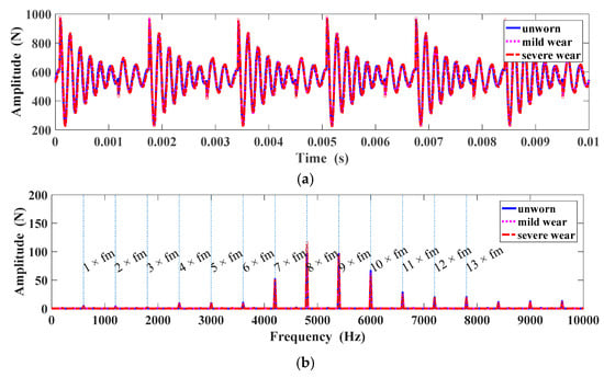
Figure 13.
Gear meshing force under different wear phases: (a) Gear meshing force; (b) Spectrum of gear meshing force.


Figure 14.
Harmonics of gear meshing force under different wear phases: (a) 1 × fm at 40 Nm; (b) 2 × fm at 40 Nm; (c) 3 × fm at 40 Nm; (d) 4 × fm at 40 Nm.
3.2. Influence of Bearing Clearances on System Dynamics
3.2.1. Gear Parameters and Gear Mesh Stiffness under Different Bearing Clearances
Figure 15 depicted the variation of gear parameters under different bearing clearances. With the increase of the bearing clearance, the actual gear center distance will increase linearly, as shown in Figure 15a. Due to the change of the gear center distance, the gear pitch circle will be increased; however, the base circle and addendum circle will remain unchanged, as these circle are machined dimensions. The pressure angle is related to the base circle and pitch circle, and the contact line length is related to the pitch circle and addendum circle. Figure 15b,c shown the variation of the pressure angle and contact line length under different bearing clearances. The reduction of the contact line length causes the decrease in contact ratio as shown in Figure 15d. The greater the contact ratio, the more stable the gear system runs.
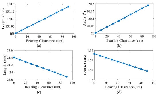
Figure 15.
Displacement in the Y direction under different bearing clearances: (a) Centre distance; (b) Operating pressure angle; (c) Contact line length; (d) Contact ratio.
Gear time-varying meshing stiffness is an important factor affecting the dynamics of gear system. The change of the bearing clearance leads to the shift of gear meshing position, which further leads to the change of gear meshing stiffness. Figure 16 shows the meshing stiffness of gears in a cycle under different bearing clearances. In Figure 17, A and C represent the double tooth mesh area respectively, and B represents the single tooth mesh area. The time-varying meshing stiffness will increase gradually with the increase of bearing clearance. At the same time, in the zoomed-in figure we can see that the double tooth mesh area was reduced, and the single tooth mesh area increased. The reason for this is that the increase of bearing clearance leads to the decrease of contact ratio, which means that the double tooth mesh area is reduced. In order to explain the change of meshing stiffness of gears with bearing clearance more clearly, the average meshing stiffness of gears in a period with different clearance is calculated as shown in Figure 17. It can be seen that the average meshing stiffness decreases linearly with the increase of bearing clearance.
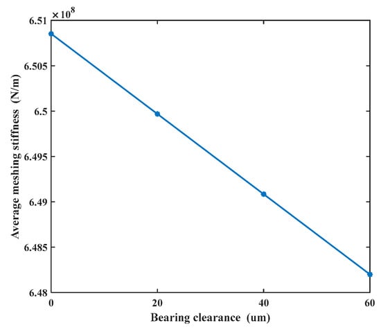
Figure 16.
The average mesh stiffness under different bearing clearances.
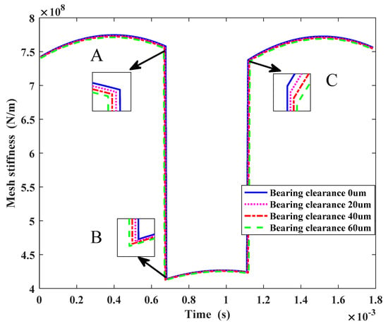
Figure 17.
The time-varying mesh stiffness under different bearing clearances.
3.2.2. Translational Displacement
Figure 18a depicted the Y-displacement under different bearing clearances. The larger the bearing clearance is, the more shift is generated. More detail on displacement in time domain is depicted in the zoomed-in figure. The spectrum of Y-displacement is shown in Figure 18b. The first four harmonics of the Y-displacement are illustrated in Figure 19. As can be seen, the first order harmonic and second order harmonic are enlarged with the increase of the wear depth and change linearly. The third order harmonic is linearly descending. However, the fourth harmonic presents a nonlinear tendency with the increase of bearing clearance.
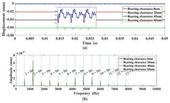
Figure 18.
Displacement in the Y direction under different bearing clearances: (a) Y-Displacement; (b) Displacement spectrum in the Y direction.
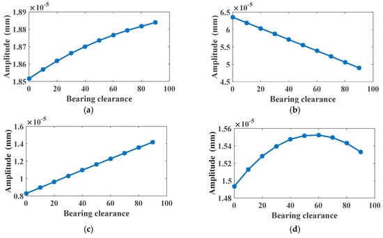
Figure 19.
Harmonics of mesh frequency in Y-displacement spectrum under different bearing clearances: (a) 1 × fm at 40 Nm; (b) 2 × fm at 40 Nm; (c) 3 × fm at 40 Nm; (d) 4 × fm at 40 Nm.

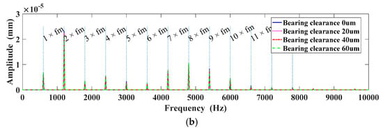
Figure 20.
Displacement in the X direction under different bearing clearances: (a) X-Displacement; (b) Displacement spectrum in the X direction.
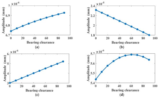
Figure 21.
Harmonics of mesh frequency in X-displacement spectrum under different bearing clearances: (a) 1 × fm at 40 Nm; (b) 2 × fm at 40 Nm; (c) 3 × fm at 40 Nm; (d) 4 × fm at 40 Nm.
3.2.3. Relative Displacement
Figure 22a depicted the relative displacement under different bearing clearances. It can be seen that the displacement curve moves upwards as a whole. More detail about displacement in the time domain is depicted in the zoomed-in figure. The spectrum of relative displacement is shown in Figure 22b. The first four harmonics of the Y-displacement are illustrated in Figure 23. As can be seen, the first order harmonic and third order harmonic are enlarged with the increase of the bearing clearance. The second order harmonic is descending. However, the fourth harmonic presents a nonlinear tendency with the increase of bearing clearance.

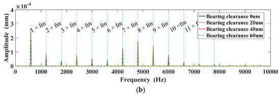
Figure 22.
Relative displacement under different bearing clearances: (a) Relative displacement; (b) Spectrum of relative displacement.
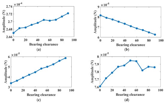
Figure 23.
Harmonics of mesh frequency in relative-displacement spectrum under different bearing clearances: (a) 1 × fm at 40 Nm; (b) 2 × fm at 40 Nm; (c) 3 × fm at 40 Nm; (d) 4 × fm at 40 Nm.
3.2.4. Gear Meshing Force
Figure 24a illustrated the time-varying gear meshing force in time domain. It can be obtained from Figure 24b that the amplitudes of eighth to tenth harmonics are much higher than that of other harmonics in the frequency band in which the signals are modulated by the resonance frequency of the gears. To investigate the variation of the gear meshing force, the first ten harmonics of the meshing frequency are illustrated in Figure 25. As can be seen, the amplitude variations of the first four harmonics are nonlinear, which is caused by the nonlinearity effect of the bearing dynamics as presented in many researches. The first order harmonics descend when the bearing clearance increases, and then they increase. The second order, fifth order, eighth order, ninth order and tenth harmonics descend when the bearing clearance increases. However, the third order, fourth order and sixth order harmonics are enlarged with the increase of the bearing clearance.
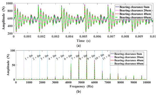
Figure 24.
Gear meshing force under different bearing clearance: (a) Gear meshing force; (b) Spectrum of gear meshing force.
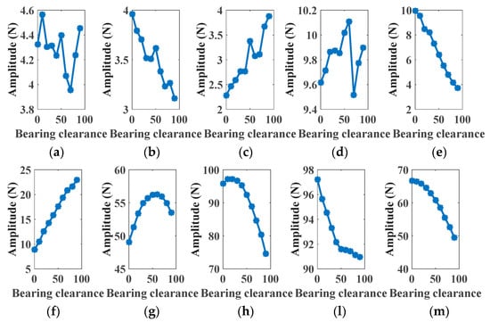
Figure 25.
Harmonics of gear meshing force under different bearing clearance: (a) 1 × fm at 40 Nm; (b) 2 × fm at 40 Nm; (c) 3 × fm at 40 Nm; (d) 4 × fm at 40 Nm; (e) 5 × fm at 40 Nm; (f) 6 × fm at 40 Nm; (g) 7 × fm at 40 Nm; (h) 8 × fm at 40 Nm; (l) 9 × fm at 40 Nm; (m) 10 × fm at 40 Nm.
4. Conclusions
- (1)
- The change of bearing clearance leads to the change of the actual center distance of gears, and the change of the center distance further affects the backlash. The relationship of the bearing clearance and backlash is deduced. It can be obtained that the backlash will increase linearly under static conditions.
- (2)
- The time-varying meshing stiffness of gear meshing under different wear phases is calculated. The time-varying meshing stiffness will increase gradually with the increase of wear depth. However, the mesh stiffness does not change significantly in the single-tooth mesh area. The translational displacement, relative displacement and dynamic meshing force will increase with the increase of the wear depth. This shows that the increase of the wear depth has negative effects on the vibration of the gear system.
- (3)
- The time-varying meshing stiffness of gear meshing under different bearing clearances is calculated. The time-varying meshing stiffness will increase gradually with the increase of bearing clearance, the double-tooth mesh area will reduce and single-tooth mesh area will increase. Also, the gear mesh parameters, like contact ratio and pressure angle, will change as the bearing clearance increases. In the meantime, the change of the bearing clearance affects the dynamic response of the system. The translational displacement, relative displacement and dynamic meshing force will increase with the increase of the bearing clearance. This shows that the increase of the bearing clearance has negative effects on the vibration of the gear system.
Author Contributions
Conceptualization, R.Z. and K.W.; Methodology, R.Z. and K.W.; Software, K.W.; Validation, R.Z. and F.G.; Formal Analysis, Y.S.; Investigation, K.W.; Resources, X.S.; Data Curation, R.Z. and K.W.; Writing—Original Draft Preparation, R.Z.; Writing—Review and Editing, R.Z. and K.W.; Visualization, T.W.; Supervision, R.Z.; Project Administration, R.Z.; Funding Acquisition, R.Z. and T.W.
Funding
This work was supported by The State Key Laboratory of Mechanical Transmission, Chongqing university, China (SKLMT-KFKT-201717); The Natural Science Foundation of China (51575178).
Acknowledgments
The author would like to thank Fengshou Gu for his assistance in providing some key ideas, and Yandong Shi and Kaida Wang and Xiuquan Sun for their assistance in revising the manuscript, and Tie Wang and for their financial support.
Conflicts of Interest
The authors declare no conflict of interest.
References
- Chen, Q.; Ma, Y.; Huang, S.; Zhai, H. Research on gears’ dynamic performance influenced by gear backlash based on fractal theory. Appl. Surf. Sci. 2014, 313, 325–332. [Google Scholar] [CrossRef]
- Flodin, A.; Andersso, S. Simulation of mild wear in spur gears. Wear 1997, 207, 16–23. [Google Scholar] [CrossRef]
- Yesilyurt, I.; Gu, F.; Ball, A.D. Gear tooth stiffness reduction measurement using modal analysis and its use in wear fault severity assessment of spur gears. NDT E Int. 2003, 36, 357–372. [Google Scholar] [CrossRef]
- Choy, F.K.; Polyshchuk, V.; Zakrajsek, J.J.; Handschuh, R.F.; Townsend, D.P. Analysis of the effects of surface pitting and wear on the vibration of a gear transmission system. Tribol. Int. 1996, 29, 77–83. [Google Scholar] [CrossRef]
- Dempsey, P.J. Integrating Oil Debris and Vibration Measurement for Intelligent Machine Health Monitoring; Tech. Rep. NASA/TM-2003-211307; Glenn Research Center: Cleveland, OH, USA, 2003. [Google Scholar]
- Kahraman, A.; Singh, R. Interaction between time-varying mesh stiffness and clearance non-linearities in a geared system. J. Sound Vib. 1991, 146, 135–156. [Google Scholar] [CrossRef]
- Chen, S.; Tang, J.; Luo, C.; Wang, Q. Nonlinear dynamic characteristics of geared rotor bearing systems with dynamic backlash and friction. Mech. Mach. Theory 2011, 46, 466–478. [Google Scholar] [CrossRef]
- Cui, Y.; Liu, Z.; Hua, Y.J. The dynamic response of the gear-rotor coupling system and the effect of the tooth side gap on the amplitude jump characteristics. J. Mech. Eng. 2009, 45, 7–15. [Google Scholar] [CrossRef]
- Gou, X.; Zhu, L.; Qi, C. Nonlinear dynamic model of a gear-rotor-bearing system considering the flash temperature. J. Sound Vib. 2017, 410, 187–208. [Google Scholar] [CrossRef]
- Xu, J.; Zeng, F.; Su, X. Coupled Bending-Torsional Nonlinear Vibration and Bifurcation Characteristics of Spiral Bevel Gear System. Shock Vib. 2017, 2017, 1–14. [Google Scholar] [CrossRef]
- Zhang, Z.; Zheng, C.; Wen, M.; Yang, S.; Li, H.; Du, Q. A Wear Prediction Model for Spur Gears Based on the Dynamic Meshing Force and Tooth Profile Reconstruction. In Proceedings of the International Conference on Computer Engineering, Information Science & Application Technology, Guilin, China, 24 September 2016. [Google Scholar] [CrossRef]
- Wojnarowski, J.; Onishchenko, V. Tooth wear effects on spur gear dynamics. Mech. Mach. Theory 2003, 38, 161–178. [Google Scholar] [CrossRef]
- Ding, H.; Kahraman, A. Interactions between nonlinear spur gear dynamics and surface wear. J. Sound Vib. 2007, 307, 662–679. [Google Scholar] [CrossRef]
- Feng, S.; Mao, J.; Xie, Y. Calculation and analysis of the influence of tooth surface abrasion on gear mesh stiffness. J. Mech. Eng. 2015, 51, 27–32. [Google Scholar] [CrossRef]
- Wang, X.S.; Wu, S.-J.; Zhou, X.H.; Hu, J.C. Nonlinear dynamics analysis of gear transmission system with wear fault. J. Vib. Shock 2013, 32, 37–43+69. [Google Scholar]
- Liu, X.; Yang, Y.; Zhang, J. Investigation on coupling effects between surface wear and dynamics in a spur gear system. Tribol. Int. 2016, 101, 383–394. [Google Scholar] [CrossRef]
- Shi, J.L.; Ma, X.G.; Xu, C.L.; Zang, S. Meshing Stiffness Analysis of Gear Using the Ishikawa Method. Appl. Mech. Mater. 2013, 401–403, 203–206. [Google Scholar] [CrossRef]
- Jiang, H.; Liu, F. Dynamic modeling and analysis of spur gears considering friction–vibration interactions. J. Braz. Soc. Mech. Sci. Eng. 2017, 39, 4911–4920. [Google Scholar] [CrossRef]
© 2019 by the authors. Licensee MDPI, Basel, Switzerland. This article is an open access article distributed under the terms and conditions of the Creative Commons Attribution (CC BY) license (http://creativecommons.org/licenses/by/4.0/).